EP2956944B1 - Ensembles cibles de réacteur nucléaire et procédés pour la production d'isotopes, la modification de matériau au sein d'un matériau cible et/ou la caractérisation de matériau au sein d'un matériau cible - Google Patents
Ensembles cibles de réacteur nucléaire et procédés pour la production d'isotopes, la modification de matériau au sein d'un matériau cible et/ou la caractérisation de matériau au sein d'un matériau cible Download PDFInfo
- Publication number
- EP2956944B1 EP2956944B1 EP13866507.0A EP13866507A EP2956944B1 EP 2956944 B1 EP2956944 B1 EP 2956944B1 EP 13866507 A EP13866507 A EP 13866507A EP 2956944 B1 EP2956944 B1 EP 2956944B1
- Authority
- EP
- European Patent Office
- Prior art keywords
- target
- annulus
- target material
- assembly
- uranium
- Prior art date
- Legal status (The legal status is an assumption and is not a legal conclusion. Google has not performed a legal analysis and makes no representation as to the accuracy of the status listed.)
- Active
Links
- 239000013077 target material Substances 0.000 title claims description 61
- 239000000463 material Substances 0.000 title claims description 41
- 238000000034 method Methods 0.000 title claims description 20
- 238000000429 assembly Methods 0.000 title description 13
- 230000000712 assembly Effects 0.000 title description 13
- 229910052770 Uranium Inorganic materials 0.000 claims description 14
- JFALSRSLKYAFGM-UHFFFAOYSA-N uranium(0) Chemical compound [U] JFALSRSLKYAFGM-UHFFFAOYSA-N 0.000 claims description 14
- 230000004907 flux Effects 0.000 claims description 13
- 238000005253 cladding Methods 0.000 claims description 9
- 238000004519 manufacturing process Methods 0.000 claims description 8
- 238000001914 filtration Methods 0.000 claims description 2
- 239000007787 solid Substances 0.000 claims 1
- 239000000446 fuel Substances 0.000 description 27
- 229910052790 beryllium Inorganic materials 0.000 description 17
- ATBAMAFKBVZNFJ-UHFFFAOYSA-N beryllium atom Chemical compound [Be] ATBAMAFKBVZNFJ-UHFFFAOYSA-N 0.000 description 16
- ZOKXTWBITQBERF-UHFFFAOYSA-N Molybdenum Chemical compound [Mo] ZOKXTWBITQBERF-UHFFFAOYSA-N 0.000 description 14
- 229910052750 molybdenum Inorganic materials 0.000 description 14
- 239000011733 molybdenum Substances 0.000 description 13
- ZOKXTWBITQBERF-AKLPVKDBSA-N Molybdenum Mo-99 Chemical group [99Mo] ZOKXTWBITQBERF-AKLPVKDBSA-N 0.000 description 11
- XLYOFNOQVPJJNP-UHFFFAOYSA-N water Substances O XLYOFNOQVPJJNP-UHFFFAOYSA-N 0.000 description 9
- 230000000694 effects Effects 0.000 description 7
- 229910052739 hydrogen Inorganic materials 0.000 description 5
- 239000001257 hydrogen Substances 0.000 description 5
- 238000011160 research Methods 0.000 description 5
- 238000012546 transfer Methods 0.000 description 5
- 239000002775 capsule Substances 0.000 description 4
- 229950009740 molybdenum mo-99 Drugs 0.000 description 4
- 229910052793 cadmium Inorganic materials 0.000 description 3
- BDOSMKKIYDKNTQ-UHFFFAOYSA-N cadmium atom Chemical compound [Cd] BDOSMKKIYDKNTQ-UHFFFAOYSA-N 0.000 description 3
- 238000010586 diagram Methods 0.000 description 3
- 230000004992 fission Effects 0.000 description 3
- 239000000203 mixture Substances 0.000 description 3
- 238000001228 spectrum Methods 0.000 description 3
- OKTJSMMVPCPJKN-UHFFFAOYSA-N Carbon Chemical compound [C] OKTJSMMVPCPJKN-UHFFFAOYSA-N 0.000 description 2
- 241000237858 Gastropoda Species 0.000 description 2
- UFHFLCQGNIYNRP-UHFFFAOYSA-N Hydrogen Chemical compound [H][H] UFHFLCQGNIYNRP-UHFFFAOYSA-N 0.000 description 2
- 241000283973 Oryctolagus cuniculus Species 0.000 description 2
- 229910001093 Zr alloy Inorganic materials 0.000 description 2
- 239000010437 gem Substances 0.000 description 2
- 229910052737 gold Inorganic materials 0.000 description 2
- 239000010439 graphite Substances 0.000 description 2
- 229910002804 graphite Inorganic materials 0.000 description 2
- 230000036541 health Effects 0.000 description 2
- 229910052741 iridium Inorganic materials 0.000 description 2
- 229910052751 metal Inorganic materials 0.000 description 2
- 239000002184 metal Substances 0.000 description 2
- 239000000843 powder Substances 0.000 description 2
- 229910052702 rhenium Inorganic materials 0.000 description 2
- 229910052717 sulfur Inorganic materials 0.000 description 2
- 238000012360 testing method Methods 0.000 description 2
- -1 uranium-zirconium-hydride Chemical compound 0.000 description 2
- WKBPZYKAUNRMKP-UHFFFAOYSA-N 1-[2-(2,4-dichlorophenyl)pentyl]1,2,4-triazole Chemical compound C=1C=C(Cl)C=C(Cl)C=1C(CCC)CN1C=NC=N1 WKBPZYKAUNRMKP-UHFFFAOYSA-N 0.000 description 1
- 229910052580 B4C Inorganic materials 0.000 description 1
- 229910052582 BN Inorganic materials 0.000 description 1
- ZOXJGFHDIHLPTG-UHFFFAOYSA-N Boron Chemical compound [B] ZOXJGFHDIHLPTG-UHFFFAOYSA-N 0.000 description 1
- PZNSFCLAULLKQX-UHFFFAOYSA-N Boron nitride Chemical compound N#B PZNSFCLAULLKQX-UHFFFAOYSA-N 0.000 description 1
- 229910001371 Er alloy Inorganic materials 0.000 description 1
- 229910000711 U alloy Inorganic materials 0.000 description 1
- 239000006096 absorbing agent Substances 0.000 description 1
- 229910052782 aluminium Inorganic materials 0.000 description 1
- XAGFODPZIPBFFR-UHFFFAOYSA-N aluminium Chemical compound [Al] XAGFODPZIPBFFR-UHFFFAOYSA-N 0.000 description 1
- 230000008901 benefit Effects 0.000 description 1
- 229910052796 boron Inorganic materials 0.000 description 1
- INAHAJYZKVIDIZ-UHFFFAOYSA-N boron carbide Chemical compound B12B3B4C32B41 INAHAJYZKVIDIZ-UHFFFAOYSA-N 0.000 description 1
- 150000001639 boron compounds Chemical class 0.000 description 1
- 238000006243 chemical reaction Methods 0.000 description 1
- 229910052804 chromium Inorganic materials 0.000 description 1
- 238000001816 cooling Methods 0.000 description 1
- 238000013461 design Methods 0.000 description 1
- 230000008030 elimination Effects 0.000 description 1
- 238000003379 elimination reaction Methods 0.000 description 1
- UYAHIZSMUZPPFV-UHFFFAOYSA-N erbium Chemical compound [Er] UYAHIZSMUZPPFV-UHFFFAOYSA-N 0.000 description 1
- 229910001751 gemstone Inorganic materials 0.000 description 1
- 230000006872 improvement Effects 0.000 description 1
- 230000001678 irradiating effect Effects 0.000 description 1
- 238000012856 packing Methods 0.000 description 1
- 229910052698 phosphorus Inorganic materials 0.000 description 1
- 230000008569 process Effects 0.000 description 1
- 238000000926 separation method Methods 0.000 description 1
- 239000010935 stainless steel Substances 0.000 description 1
- 229910001220 stainless steel Inorganic materials 0.000 description 1
- 239000011031 topaz Substances 0.000 description 1
- 229910052853 topaz Inorganic materials 0.000 description 1
- 238000012549 training Methods 0.000 description 1
- NBWXXYPQEPQUSB-UHFFFAOYSA-N uranium zirconium Chemical compound [Zr].[Zr].[U] NBWXXYPQEPQUSB-UHFFFAOYSA-N 0.000 description 1
- 239000002699 waste material Substances 0.000 description 1
- QSGNKXDSTRDWKA-UHFFFAOYSA-N zirconium dihydride Chemical compound [ZrH2] QSGNKXDSTRDWKA-UHFFFAOYSA-N 0.000 description 1
- 229910000568 zirconium hydride Inorganic materials 0.000 description 1
Images


Classifications
-
- G—PHYSICS
- G21—NUCLEAR PHYSICS; NUCLEAR ENGINEERING
- G21G—CONVERSION OF CHEMICAL ELEMENTS; RADIOACTIVE SOURCES
- G21G1/00—Arrangements for converting chemical elements by electromagnetic radiation, corpuscular radiation or particle bombardment, e.g. producing radioactive isotopes
- G21G1/02—Arrangements for converting chemical elements by electromagnetic radiation, corpuscular radiation or particle bombardment, e.g. producing radioactive isotopes in nuclear reactors
-
- G—PHYSICS
- G21—NUCLEAR PHYSICS; NUCLEAR ENGINEERING
- G21C—NUCLEAR REACTORS
- G21C23/00—Adaptations of reactors to facilitate experimentation or irradiation
-
- Y—GENERAL TAGGING OF NEW TECHNOLOGICAL DEVELOPMENTS; GENERAL TAGGING OF CROSS-SECTIONAL TECHNOLOGIES SPANNING OVER SEVERAL SECTIONS OF THE IPC; TECHNICAL SUBJECTS COVERED BY FORMER USPC CROSS-REFERENCE ART COLLECTIONS [XRACs] AND DIGESTS
- Y02—TECHNOLOGIES OR APPLICATIONS FOR MITIGATION OR ADAPTATION AGAINST CLIMATE CHANGE
- Y02E—REDUCTION OF GREENHOUSE GAS [GHG] EMISSIONS, RELATED TO ENERGY GENERATION, TRANSMISSION OR DISTRIBUTION
- Y02E30/00—Energy generation of nuclear origin
- Y02E30/30—Nuclear fission reactors
Definitions
- the present invention relates to target assemblies as well as methods for producing isotopes.
- isotopes have a significant utility for a wide range of medical applications (see, e.g., U.S. 8,126,104 ) and commercial quantities of radioisotopes such as molybdenum-99 have been produced in nuclear reactors over the years through the uranium fission process (see, e.g., U.S. 3,799,883 ).
- US2012027152 discloses a target assembly comprising an annulus containing a fissile material such as uranium ( 235 U) interspersed with one or more voided regions, located between an outer diameter wall and an inner diameter wall. A central region within the inner diameter wall is used for cooling and/or for the collection of fission products.
- a fissile material such as uranium ( 235 U)
- At least one advantage of embodiments of the present invention is the substantial elimination of significant amounts of unwanted fission products from the product radioisotope and what may accompany same as a large array of concomitant undesirable infrastructure, health, security, and waste issues and/or associated costs required for this separation.
- the present invention provides a target assembly comprising an annulus comprising uranium, and defining an outer diameter defining a volume within the annulus; and target material for producing isotopes within the volume of the annulus, the target material consisting essentially of non-uranium material.
- the present invention provides a method for producing isotopes within target material, the method comprising providing neutrons to target material within a uranium-comprising annulus, the target material consisting essentially of non-uranium metal.
- isotopes can be prepared at a desired activity level using a lower neutron flux than would be needed for the same target material without the uranium-comprising annulus.
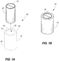
- Target assembly 10 includes a uranium-comprising annulus 14.
- the annulus defines an outer diameter 15 and an inner diameter 17.
- the inner diameter defines a volume 19 within annulus 14.
- Annulus 14 can comprise less than about 20% enrichment of 235 U.
- annulus 14 can include an alloy of uranium and erbium, for example.
- annulus 14 can comprise uranium-zirconium alloys (UZr) and/or uranium-zirconium-hydride (UZrH x ).
- the annulus has at least one cross section.
- the distance between inner diameter 17 and outer diameter 15 may range from about 100 ⁇ m to about 1 cm in one cross section.
- Annulus 14 can define a length extending between opposing openings to volume 19. This length can range from 0.5 to 50 cm. In accordance with example embodiments, the length can be greater than 1 cm and/or less than 38 cm, for example.
- Assembly 10 includes a target material 12 that is received within volume 19 of annulus 14.
- Target material 12 consists essentially of non-uranium-comprising material.
- Material 12 "consists essentially of" non-uranium-comprising material when, the material contains uranium, if at all, it is contained in such insubstantial amounts that the uranium does not require removal from the target material, and/or does not provide decay products that require removal from the target material.
- Non-uranium-comprising material may also be material requiring no special uranium related radiological or health physics protocols for handling or for transporting the material; such as safety and/or disposal procedures.
- material 12 may contain inconsequential amounts of uranium and/or consist of non-uranium-comprising material.
- Material 12 can include at least one of Mo, P, S Ir, Au, Re, and/or Cr.
- Material 12 can have a diameter less than about 10 cm or more specifically a diameter from about 500 micron to about 5 cm; Material 12 can also have a length of about 3 cm; and multiple discrete target materials can be engaged within volume 19 of annulus 14.
- annulus 14 may have a length of about 38 cm and material and/or materials 12 may occupy all or a portion of volume 19 of that length.
- Material 12 may occupy a terminal 12.7 to 15 cm of the length of annulus 14; accordingly this can include the bottom 12.7 to 15 cm of the length of annulus 14, for example.
- target material 12 and/or annulus 14 includes cladding 16 extending entirely or at least partially over any or all surfaces.
- the cladding can include Zr, zircalloy and/or stainless steel, for example.
- Material 12 can be configured to be removeably coupled to annulus 14.
- target assembly 20 is shown in accordance with another embodiment.
- assembly 20 includes target material 12 as well as annulus 14.
- liner 22 is associated with the inner diameter of annulus 14.
- the liner 22 can comprise boron, boron carbide, boron nitride, and/or cadmium, for example.
- Liner 22 can be commensurate in length with the length of target material 12 and/or may be commensurate in length with the length of the inner diameter of annulus 14, for example.
- An example thickness of liner 22 comprised of cadmium can be 390 micro-meters thick but may be as thick as about 5 centimeter.
- Target material 12, liner 22 and/or annulus 14 may be configured to slidably engage one another to form a portion or all of target assembly 20.
- a target assembly 30 that includes target material 12, liner 22, annulus 14 and reflector 32.
- Reflector 32 can include beryllium or lead.
- Reflector 32 may also include a mixture of beryllium and/or lead with other compositions such as graphite, for example.
- Reflector 32 may have a cross section that defines a thickness less than about 1 cm, for example, and it may be configured as one or more components that are arranged along a perimeter of the target material and/or annulus.
- Reflector 32 may have a 0.16 cm thickness with an inner radius of 1.74 cm in one cross section.
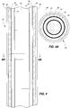
- target assembly 42 is shown in accordance with another embodiment.
- Fig. 4 represents at least one cross section of target assembly 42 and
- Fig. 4A represents a transverse cross section of target assembly 42 as well.
- a volume within annulus 14 is defined in at least one cross section.
- Target material 12 can occupy an entirety of the volume defined in this cross section.
- Assembly 42 can include additional components, such as cladding, liners, and/or reflectors. Material 12 can occupy an entirety of the volume defined in the cross section inclusive of these additional materials. For example, where assembly 42 includes liner 22, a volume is defined in the one cross section and material 12 can occupy an entirety of this volume.
- Target assembly 42 is configured as a can.
- target assembly 42 includes a can wall 44 that may include aluminum, for example, and adjacent can wall 44 is a reflector 32.
- Cladding 16 is over annulus 14 having liner 22 between annulus 14 and target material 12. As can be seen in Fig. 4 , assembly 42 includes multiple discrete target materials 12.
- FIG. 5 another target assembly 52 is shown that includes at least one cross section shown in Fig. 5 and a transverse cross section shown in Fig. 5A .
- Can wall 44 encompasses reflector material 32 which is associated with cladding 16 of annulus 14 having liner 22 between annulus 14 and target material 12.
- Target assembly 52 includes one or more caps 54; and disposed adjacent caps 54 is additional reflector material 32.
- the mass of the entire target assembly (as shown in figures 1 , 2 , 3 , 4 and 5 ) can be from about 10 grams to about 5000 grams.
- the mass can be from about 50 grams to 3000 grams.
- the diameter of the entire target assembly can be from about 1 centimeter to about 10 centimeters.
- the diameter can be from about 3 to 6 centimeters.
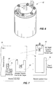
- a transfer cask assembly 62 is shown for use with target assemblies such as target assembly 52 in the form of a can configuration.
- a reactor core pool has a perimeter of core 72 and a discrete zone 74 configured to receive a can assembly such as target assembly 52.
- target material 12 can include 2 grams of 99.999% pure molybdenum metal powder, for example.
- Discrete zone 74 can be at a position such as D8 (described later with reference to reactors as 126 in Figure 12 ). Assembly 52 is removed and transferred to a transfer cask assembly 62 and eventually transferred to a reactor laydown area 76.
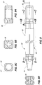
- target assembly 82 is shown according to another embodiment of the invention.
- Target assembly 82 is shown in one cross section in Fig. 8 and a transverse cross section in Fig. 8A .
- Target assembly 82 may also be considered a fuel element arrangement.
- Target assembly 82 includes a cladding 16 encompassing additional cladding over annulus 14 having liner 22 in between annulus 14 and target material 12.
- Target assembly 82 includes fixtures 88. Fixtures 88 are configured to be received by portions of a cluster assembly to allow for the transfer of assembly 82.
- Assembly 82 also includes liner material 22 associated with target material 12. Liner material 22 is placed in between target material 12 and reflector material 84 as well.
- Reflector material 84 can be a mixture of graphite and beryllium, for example. Reflector material 84 may also function as a packing material in some implementations.
- a cluster assembly 92 is shown that includes one or more elements 82 coupled to base 96 and handle 94.
- Cross sections of cluster assembly 9 are shown in Fig. 9A-9D .
- a recess 97 is shown within base 96 that also includes sockets 98 that are configured to receive fixtures 88, for example.
- socket 98 is shown according to another cross section, and referring to Fig. 9D , socket 99 is shown and configured to receive another fixture 88, for example.
- Base 96 is configured as shown in Fig. 9C .
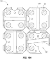
- arrangement 102 shows a cross section of different base arrangements 96 having assemblies 82 therein.
- arrangement 104 includes clusters having a handle 104 with a cutout 108 to provide clearance for the removal of an annulus without requiring removal of the entire fuel assembly to retrieve the target
- a molybdenum target can be inserted into a position with an annular uranium element.
- the target can be irradiated.
- the irradiated molybdenum can be retrieved and cooled, providing a molybdenum-99 radioisotope.
- Reactor 122 has one or more discrete zones configured to receive target material; a core position 124 as well as a perimeter position 126 (sometimes referred to as the D8 position) are considered to be one or more of these zones.
- the target material consists essentially of non-uranium material as described herein.
- Reactor 122 can also include at least one uranium-comprising annulus individually with the one or more discrete zones, the annulus being as described herein with the volume of the annulus configured to receive an entirety of the target material in at least one cross section.
- the annulus can be coupled to the reactor and/or may also be removable from the reactor.
- Neutrons can be provided by the reactor to the target material as a neutron flux which is increased within the annulus as a result of the concentrating effects of the annulus, for example.
- Discrete zones may also include one or more reflector components arranged along the perimeter of the target material and/or annulus.
- Methods also include reflecting of the neutrons by, e.g., the reflector components, to create a flux trap within the annulus.
- the discrete zone may also include one or more liners associated with the inner diameter of the annulus.
- the methods can also include filtering the neutrons as they are provided to the target material. Liners 22 comprised of materials such as cadmium or boron compounds can be selected that absorb the thermal neutrons produced in the reactor core, allowing the epithermal and fast neutrons to selectively pass to the target material.
- the thermal neutron spectrum can include energy levels less than 1 electron-volt (eV).
- the epithermal or resonance neutron spectrum can include energy levels greater than 1 eV but less than about 0.5 MeV, while the fast neutron spectrum can include energy levels greater than about 0.5 MeV.
- the production of the high energy neutrons using the target assembly may be used to treat or to modify materials such as gemstones. Gemologists treat gems such as topaz with epithermal and fast neutrons, for example.
- the target material as described above consists essentially of non-uranium-comprising material, such as P, S, Ir, Au, Re, Cr and Mo.
- the neutrons that interact with the target material can, produce one or more of 32 P, 35 S, 192 Ir, 198 Au, 186 Re, 51 Cr, and 99 Mo.
- Rabbit systems can include pneumatic systems to automatically transport the target material to and from the reactor core.
- the target material can be positioned in a transport capsule, and the transport capsule can be positioned into the sending station of the pneumatic tube.
- the target material in the capsule can then be pneumatically transported to the reactor core.
- the target material in the capsule can then be pneumatically transported to the receiving station of the pneumatic tube.
- Figs. 13-15 depict data acquired from different target configurations in the core of research test reactors using uranium zirconium hydride (UZrH x ) fuel. Modeling the performance of unique target assemblies under a variety of conditions can be performed consistent with MCNPX 2.6.0 Extensions, by Hendricks et.al., 2008). The data can be based on the core design and fuel configuration of the research reactor located at Washington State University (WSU) in Pullman, Washington.
- WSU Washington State University
- the research reactor at WSU is a 1-MegaWatt with Training, Research, Isotopes, General Atomics (TRIGA) fuel and a thermal neutron flux of about 2e10 12 neutron/centimeter 2 -sec outside the core.
- TRIGA General Atomics
- Example target materials included pressed molybdenum with a bulk density of 8 g/cc.
- the target configurations could include 1) molybdenum cylinders, 2) molybdenum cylinders and annuli surrounded by beryllium, and 3) molybdenum cylinders surrounded by UZrH fuel with and without beryllium or lead reflectors/absorbers. The configurations are further described below in relation to the discrete zone in which the target assembly may be placed within the reactor:
- FIG. 13 shows the production of 99 Mo in a specimen target located out-of-core from 12 to 144 hours. After 72 hours, the production of 99 Mo is 3.8 curie. After 144 hours, the production of 99 Mo is only 5.6 Ci, or only 1.8 Ci more than produced during the first 72 hours.
- the two target positions for the purpose of modeling calculations are graphically shown in Fig. 12 as positions 124 and 126. Position 126 (D8) is outside of the core, and position 124 (D5) is inside the core where the higher flux is produced.
- Each core position (D5) may have four fuel elements configured as shown in Figs 9 and 10 , for example.
- a molybdenum target can replace one of the fuel elements in the assembly.
- Table 1 The modeling results are shown in Table 1 below. The data can indicate that it is possible to produce about 1000 Ci @ 1.0 Ci/g in a single fuel annulus and a beryllium reflector (1 target position at peak flux in D5). Alternatively, about 1000 Ci @ 0.4 Ci/g may be produced with a larger molybdenum target cylinder in just water. The data further indicates that a four-fold increase in the total curie values can be achieved with four targets replacing four fuel locations.
- Fig. 14 demonstrates a Log-Log plot superimposing the neutron flux of position D8 in water with the cross section for 98 Mo( ⁇ , ⁇ ) 99 Mo. The group average shows the integrated flux over the discrete 95 energy bins.
- Fig. 15 demonstrates a Log-Log plot superimposing the neutron flux of position D8 in water (out-of-core) with center of the core (position D5) in the research reactor.
- the irradiated target material can be processed utilizing the materials and/or methods described in US patent publication US2012/0106691 to Toth et al. entitled “Method and System for Radioisotope Generation”, published May 3, 2012.
Landscapes
- Physics & Mathematics (AREA)
- Engineering & Computer Science (AREA)
- Plasma & Fusion (AREA)
- General Engineering & Computer Science (AREA)
- High Energy & Nuclear Physics (AREA)
- Chemical & Material Sciences (AREA)
- Chemical Kinetics & Catalysis (AREA)
- General Chemical & Material Sciences (AREA)
- Particle Accelerators (AREA)
- Manufacture And Refinement Of Metals (AREA)
- Powder Metallurgy (AREA)
Claims (11)
- Ensemble cible (10) de réacteur nucléaire pour produire des isotopes comprenant :un anneau (14) comprenant de l'uranium, et définissant un diamètre extérieur (15) et un diamètre intérieur (17), le diamètre intérieur (17) définissant un volume (19) à l'intérieur de l'anneau (14) ; etun matériau cible (12) pour produire des isotopes,caractérisé en ce que le matériau cible (12) est situé à l'intérieur du volume (19) de l'anneau (14), et est constitué essentiellement de matériau ne consistant pas en uranium.
- Ensemble cible (10) selon la revendication 1, comprenant en outre un ou plusieurs composants réflecteurs (32) disposés le long d'un périmètre du matériau cible (12) et/ou de l'anneau (14).
- Ensemble cible (10) selon la revendication 1, comprenant en outre au moins un chemisage (22) disposé le long du diamètre intérieur (17) de l'anneau (14).
- Ensemble cible (10) selon la revendication 1, comprenant en outre un gainage (16) sur au moins une partie d'une surface de l'un ou des deux parmi l'anneau (14) et/ou le matériau cible (12).
- Ensemble cible (10) selon la revendication 1, comprenant en outre au moins un chemisage (22) disposé le long du diamètre intérieur (17) de l'anneau (14), le matériau cible (12) occupant la totalité du volume (19) défini par l'anneau (14) et le chemisage (22) dans au moins une section transversale.
- Ensemble cible (10) selon la revendication 1, comprenant en outre un gainage (16) sur au moins une partie d'une surface de l'un ou des deux parmi l'anneau (14) et/ou le matériau cible (12), le matériau cible (12) occupant la totalité du volume (19) défini par l'anneau (14) dans au moins une section transversale.
- Ensemble cible (10) selon la revendication 1, dans lequel le matériau cible (12) est solide.
- Procédé pour produire des isotopes dans un réacteur nucléaire au sein d'un matériau cible (12),
le procédé comprenant la fourniture de neutrons au matériau cible (12) à l'intérieur d'un anneau comprenant de l'uranium (14),
caractérisé en ce que le matériau cible (12) est constitué essentiellement de matériau ne consistant pas en uranium. - Procédé selon la revendication 8, dans lequel les neutrons sont fournis au matériau cible (12) à l'intérieur de l'anneau comprenant de l'uranium (14) pour augmenter le flux de neutrons à l'intérieur de l'anneau (14).
- Procédé selon la revendication 8, comprenant en outre la réflexion des neutrons pour créer un piège à flux à l'intérieur de l'anneau (14).
- Procédé selon la revendication 8, comprenant en outre la filtration des neutrons lorsqu'ils sont fournis au matériau cible (12).
Applications Claiming Priority (2)
| Application Number | Priority Date | Filing Date | Title |
|---|---|---|---|
| US13/766,600 US9997267B2 (en) | 2013-02-13 | 2013-02-13 | Nuclear reactor target assemblies, nuclear reactor configurations, and methods for producing isotopes, modifying materials within target material, and/or characterizing material within a target material |
| PCT/US2013/075121 WO2014137439A2 (fr) | 2013-02-13 | 2013-12-13 | Ensembles cibles de réacteur nucléaire, configurations de réacteur nucléaire et procédés pour la production d'isotopes, la modification de matériau au sein d'un matériau cible et/ou la caractérisation de matériau au sein d'un matériau cible |
Publications (2)
| Publication Number | Publication Date |
|---|---|
| EP2956944A2 EP2956944A2 (fr) | 2015-12-23 |
| EP2956944B1 true EP2956944B1 (fr) | 2020-02-26 |
Family
ID=50983094
Family Applications (1)
| Application Number | Title | Priority Date | Filing Date |
|---|---|---|---|
| EP13866507.0A Active EP2956944B1 (fr) | 2013-02-13 | 2013-12-13 | Ensembles cibles de réacteur nucléaire et procédés pour la production d'isotopes, la modification de matériau au sein d'un matériau cible et/ou la caractérisation de matériau au sein d'un matériau cible |
Country Status (6)
| Country | Link |
|---|---|
| US (1) | US9997267B2 (fr) |
| EP (1) | EP2956944B1 (fr) |
| AU (1) | AU2013380981B2 (fr) |
| CA (1) | CA2900685C (fr) |
| MX (1) | MX357313B (fr) |
| WO (1) | WO2014137439A2 (fr) |
Families Citing this family (38)
| Publication number | Priority date | Publication date | Assignee | Title |
|---|---|---|---|---|
| US9320316B2 (en) | 2013-03-14 | 2016-04-26 | Under Armour, Inc. | 3D zonal compression shoe |
| US10039343B2 (en) | 2015-05-08 | 2018-08-07 | Under Armour, Inc. | Footwear including sole assembly |
| US10010133B2 (en) | 2015-05-08 | 2018-07-03 | Under Armour, Inc. | Midsole lattice with hollow tubes for footwear |
| US10010134B2 (en) | 2015-05-08 | 2018-07-03 | Under Armour, Inc. | Footwear with lattice midsole and compression insert |
| DE102015212099B4 (de) | 2015-06-29 | 2022-01-27 | Adidas Ag | Sohlen für Sportschuhe |
| CN106851957B (zh) * | 2017-01-03 | 2019-04-19 | 中国原子能科学研究院 | 一种用于制备辐照铀箔靶件的靶件挤胀器 |
| US11363709B2 (en) * | 2017-02-24 | 2022-06-14 | BWXT Isotope Technology Group, Inc. | Irradiation targets for the production of radioisotopes |
| US10575588B2 (en) | 2017-03-27 | 2020-03-03 | Adidas Ag | Footwear midsole with warped lattice structure and method of making the same |
| US10932521B2 (en) | 2017-03-27 | 2021-03-02 | Adidas Ag | Footwear midsole with warped lattice structure and method of making the same |
| US10779614B2 (en) | 2017-06-21 | 2020-09-22 | Under Armour, Inc. | Cushioning for a sole structure of performance footwear |
| USD880131S1 (en) | 2018-02-15 | 2020-04-07 | Adidas Ag | Sole |
| USD880122S1 (en) | 2018-02-15 | 2020-04-07 | Adidas Ag | Sole |
| USD879434S1 (en) | 2018-02-15 | 2020-03-31 | Adidas Ag | Sole |
| USD880120S1 (en) | 2018-02-15 | 2020-04-07 | Adidas Ag | Sole |
| USD882227S1 (en) | 2018-02-15 | 2020-04-28 | Adidas Ag | Sole |
| USD879428S1 (en) | 2018-02-15 | 2020-03-31 | Adidas Ag | Sole |
| USD890485S1 (en) | 2018-11-12 | 2020-07-21 | Adidas Ag | Shoe |
| TWI769552B (zh) * | 2019-10-14 | 2022-07-01 | 美商西屋電器公司 | 模組化放射線同位素生產囊室及其相關方法 |
| US11832374B1 (en) | 2020-10-01 | 2023-11-28 | Consolidated Nuclear Security, LLC | Method of making an annular radioisotope target having a helical coil-shaped foil ribbon between cladding tubes |
| USD1022425S1 (en) | 2020-10-07 | 2024-04-16 | Adidas Ag | Shoe |
| US11786008B2 (en) | 2020-10-07 | 2023-10-17 | Adidas Ag | Footwear with 3-D printed midsole |
| USD980595S1 (en) | 2020-10-13 | 2023-03-14 | Adidas Ag | Shoe |
| US12082646B2 (en) | 2020-10-13 | 2024-09-10 | Adidas Ag | Footwear and footwear components having a mesh component |
| US11992084B2 (en) | 2020-10-13 | 2024-05-28 | Adidas Ag | Footwear midsole with 3-D printed mesh having an anisotropic structure and methods of making the same |
| USD980594S1 (en) | 2020-10-13 | 2023-03-14 | Adidas Ag | Shoe |
| US11589647B2 (en) | 2020-10-13 | 2023-02-28 | Adidas Ag | Footwear midsole with anisotropic mesh and methods of making the same |
| JP2022069253A (ja) * | 2020-10-23 | 2022-05-11 | 三菱重工業株式会社 | 放射性同位体の生産管理装置、放射性同位体の生産管理方法及び放射性同位体の生産管理プログラム |
| WO2022218452A1 (fr) * | 2021-04-16 | 2022-10-20 | Fyzikalni Ustav Av Cr, V.V.I. | Cible nucléaire, procédé pour induire une réaction nucléaire et dispositif approprié pour la mise en œuvre du procédé |
| US20240233973A9 (en) * | 2022-10-25 | 2024-07-11 | Westinghouse Electric Company Llc | Additively manufactured cobalt burnable absorber capsules |
| US12414602B2 (en) | 2023-12-29 | 2025-09-16 | Adidas Ag | Additively manufactured footwear soles |
| US12446655B2 (en) | 2023-12-29 | 2025-10-21 | Adidas Ag | Soles having a co-molded lattice structure and solid region, footwear having the sole, and methods of manufacturing the same |
| US12446662B2 (en) | 2024-01-05 | 2025-10-21 | Adidas Ag | Additively manufactured footwear |
| USD1092030S1 (en) | 2024-01-05 | 2025-09-09 | Adidas Ag | Shoe |
| US20250259762A1 (en) * | 2024-02-10 | 2025-08-14 | Westinghouse Electric Company Llc | Radioisotope production target for producing radioisotopes using photoneutron production process |
| US12550975B2 (en) | 2024-05-31 | 2026-02-17 | Adidas Ag | Modular footwear and methods of making the same |
| US12527378B2 (en) | 2024-05-31 | 2026-01-20 | Adidas Ag | Integrated footwear components and footwear comprising the same |
| CN119889755B (zh) * | 2025-01-14 | 2025-10-17 | 中国核动力研究设计院 | 一种适用于研究堆辐照生产铱-192的靶材布置装置 |
| CN120108806B (zh) * | 2025-02-19 | 2026-01-02 | 华能国际电力股份有限公司 | 基于球床式高温气冷堆侧反射层辐照的同位素生产方法 |
Family Cites Families (14)
| Publication number | Priority date | Publication date | Assignee | Title |
|---|---|---|---|---|
| US3799883A (en) | 1971-06-30 | 1974-03-26 | Union Carbide Corp | Production of high purity fission product molybdenum-99 |
| GB2098787B (en) * | 1981-05-19 | 1985-09-18 | British Nuclear Fuels Ltd | Production of pellets for nuclear fuel elements |
| GB2282478B (en) | 1993-10-01 | 1997-08-13 | Us Energy | Method of fabricating 99Mo production targets using low enriched uranium |
| CA2134264C (fr) | 1994-10-25 | 2000-09-12 | William T. Hancox | Methode pour la production de molybdene-99 et gestion des dechets qui en contiennent |
| US20060023829A1 (en) | 2004-08-02 | 2006-02-02 | Battelle Memorial Institute | Medical radioisotopes and methods for producing the same |
| US8326775B2 (en) | 2005-10-26 | 2012-12-04 | Cortica Ltd. | Signature generation for multimedia deep-content-classification by a large-scale matching system and method thereof |
| US8625731B2 (en) * | 2006-04-14 | 2014-01-07 | Charles S. Holden | Compact neutron generator for medical and commercial isotope production, fission product purification and controlled gamma reactions for direct electric power generation |
| US20080013666A1 (en) * | 2006-07-17 | 2008-01-17 | Swaminathan Vaidyanathan | Method for in-situ production of hyperstoichiometric oxide fuel |
| PL2294582T3 (pl) * | 2008-05-02 | 2019-02-28 | Shine Medical Technologies, Inc. | Urządzenie i sposób wytwarzania izotopów medycznych |
| US8488733B2 (en) * | 2009-08-25 | 2013-07-16 | Ge-Hitachi Nuclear Energy Americas Llc | Irradiation target retention assemblies for isotope delivery systems |
| WO2012003009A2 (fr) * | 2010-01-28 | 2012-01-05 | Shine Medical Technologies, Inc. | Chambre de réaction segmentée pour production de radio-isotope |
| US9177679B2 (en) | 2010-02-11 | 2015-11-03 | Uchicago Argonne, Llc | Accelerator-based method of producing isotopes |
| AU2011282744B2 (en) * | 2010-07-29 | 2014-11-06 | The State Of Oregon Acting By And Through The State Board Of Higher Education On Behalf Of Oregon State University | Isotope production target |
| US8781055B2 (en) | 2010-11-03 | 2014-07-15 | Battelle Memorial Institute | Method and system for radioisotope generation |
-
2013
- 2013-02-13 US US13/766,600 patent/US9997267B2/en not_active Expired - Fee Related
- 2013-12-13 EP EP13866507.0A patent/EP2956944B1/fr active Active
- 2013-12-13 MX MX2015010289A patent/MX357313B/es active IP Right Grant
- 2013-12-13 CA CA2900685A patent/CA2900685C/fr not_active Expired - Fee Related
- 2013-12-13 WO PCT/US2013/075121 patent/WO2014137439A2/fr not_active Ceased
- 2013-12-13 AU AU2013380981A patent/AU2013380981B2/en not_active Ceased
Non-Patent Citations (1)
| Title |
|---|
| "Thermonuclear Weapon", 11 January 2013 (2013-01-11), Retrieved from the Internet <URL:https://en.wikipedia.org/w/index.php?title=Thermonuclear_weapon&oldid=532489437> * |
Also Published As
| Publication number | Publication date |
|---|---|
| WO2014137439A2 (fr) | 2014-09-12 |
| US9997267B2 (en) | 2018-06-12 |
| CA2900685A1 (fr) | 2014-09-12 |
| AU2013380981B2 (en) | 2018-11-01 |
| MX357313B (es) | 2018-07-05 |
| AU2013380981A1 (en) | 2015-08-27 |
| US20140226773A1 (en) | 2014-08-14 |
| MX2015010289A (es) | 2016-04-11 |
| CA2900685C (fr) | 2021-03-30 |
| EP2956944A2 (fr) | 2015-12-23 |
| WO2014137439A3 (fr) | 2015-02-26 |
| WO2014137439A8 (fr) | 2014-12-24 |
Similar Documents
| Publication | Publication Date | Title |
|---|---|---|
| EP2956944B1 (fr) | Ensembles cibles de réacteur nucléaire et procédés pour la production d'isotopes, la modification de matériau au sein d'un matériau cible et/ou la caractérisation de matériau au sein d'un matériau cible | |
| KR101716842B1 (ko) | 동위원소 생성 타겟 | |
| JP7626762B2 (ja) | モジュール式放射性同位体生成カプセルおよび関連方法 | |
| RU2645718C2 (ru) | Способ наработки радиоактивных изотопов в ядерном реакторе на быстрых нейтронах | |
| US12254997B2 (en) | Fuel fabrication process for radioisotope thermoelectric generators | |
| RU2769482C1 (ru) | Облучательное устройство для наработки изотопа со-60 в реакторе на быстрых нейтронах | |
| RU2769482C9 (ru) | Облучательное устройство для наработки изотопа со-60 в реакторе на быстрых нейтронах | |
| CN119274839A (zh) | 一种压水堆中辐照生产60Co的靶棒及包含其的靶件 | |
| Gohar et al. | Accelerator Driven Subcritical Facility Design Concept | |
| US20110080986A1 (en) | Method of transmuting very long lived isotopes | |
| AU2015200445B2 (en) | Isotope production target | |
| Ponsard et al. | Production of Radioisotopes and NTD-Silicon in the BR2 Reactor | |
| Woloshun et al. | Comparison of 2 Lead-Bismuth Spallation Neutron Targets |
Legal Events
| Date | Code | Title | Description |
|---|---|---|---|
| PUAI | Public reference made under article 153(3) epc to a published international application that has entered the european phase |
Free format text: ORIGINAL CODE: 0009012 |
|
| 17P | Request for examination filed |
Effective date: 20150903 |
|
| AK | Designated contracting states |
Kind code of ref document: A2 Designated state(s): AL AT BE BG CH CY CZ DE DK EE ES FI FR GB GR HR HU IE IS IT LI LT LU LV MC MK MT NL NO PL PT RO RS SE SI SK SM TR |
|
| AX | Request for extension of the european patent |
Extension state: BA ME |
|
| DAX | Request for extension of the european patent (deleted) | ||
| 17Q | First examination report despatched |
Effective date: 20160616 |
|
| STAA | Information on the status of an ep patent application or granted ep patent |
Free format text: STATUS: EXAMINATION IS IN PROGRESS |
|
| GRAP | Despatch of communication of intention to grant a patent |
Free format text: ORIGINAL CODE: EPIDOSNIGR1 |
|
| STAA | Information on the status of an ep patent application or granted ep patent |
Free format text: STATUS: GRANT OF PATENT IS INTENDED |
|
| INTG | Intention to grant announced |
Effective date: 20190919 |
|
| GRAS | Grant fee paid |
Free format text: ORIGINAL CODE: EPIDOSNIGR3 |
|
| GRAA | (expected) grant |
Free format text: ORIGINAL CODE: 0009210 |
|
| STAA | Information on the status of an ep patent application or granted ep patent |
Free format text: STATUS: THE PATENT HAS BEEN GRANTED |
|
| AK | Designated contracting states |
Kind code of ref document: B1 Designated state(s): AL AT BE BG CH CY CZ DE DK EE ES FI FR GB GR HR HU IE IS IT LI LT LU LV MC MK MT NL NO PL PT RO RS SE SI SK SM TR |
|
| REG | Reference to a national code |
Ref country code: GB Ref legal event code: FG4D |
|
| REG | Reference to a national code |
Ref country code: CH Ref legal event code: EP |
|
| REG | Reference to a national code |
Ref country code: AT Ref legal event code: REF Ref document number: 1238628 Country of ref document: AT Kind code of ref document: T Effective date: 20200315 |
|
| REG | Reference to a national code |
Ref country code: IE Ref legal event code: FG4D |
|
| REG | Reference to a national code |
Ref country code: DE Ref legal event code: R096 Ref document number: 602013066332 Country of ref document: DE |
|
| PG25 | Lapsed in a contracting state [announced via postgrant information from national office to epo] |
Ref country code: FI Free format text: LAPSE BECAUSE OF FAILURE TO SUBMIT A TRANSLATION OF THE DESCRIPTION OR TO PAY THE FEE WITHIN THE PRESCRIBED TIME-LIMIT Effective date: 20200226 Ref country code: RS Free format text: LAPSE BECAUSE OF FAILURE TO SUBMIT A TRANSLATION OF THE DESCRIPTION OR TO PAY THE FEE WITHIN THE PRESCRIBED TIME-LIMIT Effective date: 20200226 Ref country code: NO Free format text: LAPSE BECAUSE OF FAILURE TO SUBMIT A TRANSLATION OF THE DESCRIPTION OR TO PAY THE FEE WITHIN THE PRESCRIBED TIME-LIMIT Effective date: 20200526 |
|
| REG | Reference to a national code |
Ref country code: NL Ref legal event code: MP Effective date: 20200226 |
|
| REG | Reference to a national code |
Ref country code: LT Ref legal event code: MG4D |
|
| PG25 | Lapsed in a contracting state [announced via postgrant information from national office to epo] |
Ref country code: SE Free format text: LAPSE BECAUSE OF FAILURE TO SUBMIT A TRANSLATION OF THE DESCRIPTION OR TO PAY THE FEE WITHIN THE PRESCRIBED TIME-LIMIT Effective date: 20200226 Ref country code: LV Free format text: LAPSE BECAUSE OF FAILURE TO SUBMIT A TRANSLATION OF THE DESCRIPTION OR TO PAY THE FEE WITHIN THE PRESCRIBED TIME-LIMIT Effective date: 20200226 Ref country code: BG Free format text: LAPSE BECAUSE OF FAILURE TO SUBMIT A TRANSLATION OF THE DESCRIPTION OR TO PAY THE FEE WITHIN THE PRESCRIBED TIME-LIMIT Effective date: 20200526 Ref country code: IS Free format text: LAPSE BECAUSE OF FAILURE TO SUBMIT A TRANSLATION OF THE DESCRIPTION OR TO PAY THE FEE WITHIN THE PRESCRIBED TIME-LIMIT Effective date: 20200626 Ref country code: GR Free format text: LAPSE BECAUSE OF FAILURE TO SUBMIT A TRANSLATION OF THE DESCRIPTION OR TO PAY THE FEE WITHIN THE PRESCRIBED TIME-LIMIT Effective date: 20200527 Ref country code: HR Free format text: LAPSE BECAUSE OF FAILURE TO SUBMIT A TRANSLATION OF THE DESCRIPTION OR TO PAY THE FEE WITHIN THE PRESCRIBED TIME-LIMIT Effective date: 20200226 |
|
| PG25 | Lapsed in a contracting state [announced via postgrant information from national office to epo] |
Ref country code: NL Free format text: LAPSE BECAUSE OF FAILURE TO SUBMIT A TRANSLATION OF THE DESCRIPTION OR TO PAY THE FEE WITHIN THE PRESCRIBED TIME-LIMIT Effective date: 20200226 |
|
| PG25 | Lapsed in a contracting state [announced via postgrant information from national office to epo] |
Ref country code: SK Free format text: LAPSE BECAUSE OF FAILURE TO SUBMIT A TRANSLATION OF THE DESCRIPTION OR TO PAY THE FEE WITHIN THE PRESCRIBED TIME-LIMIT Effective date: 20200226 Ref country code: PT Free format text: LAPSE BECAUSE OF FAILURE TO SUBMIT A TRANSLATION OF THE DESCRIPTION OR TO PAY THE FEE WITHIN THE PRESCRIBED TIME-LIMIT Effective date: 20200719 Ref country code: DK Free format text: LAPSE BECAUSE OF FAILURE TO SUBMIT A TRANSLATION OF THE DESCRIPTION OR TO PAY THE FEE WITHIN THE PRESCRIBED TIME-LIMIT Effective date: 20200226 Ref country code: LT Free format text: LAPSE BECAUSE OF FAILURE TO SUBMIT A TRANSLATION OF THE DESCRIPTION OR TO PAY THE FEE WITHIN THE PRESCRIBED TIME-LIMIT Effective date: 20200226 Ref country code: SM Free format text: LAPSE BECAUSE OF FAILURE TO SUBMIT A TRANSLATION OF THE DESCRIPTION OR TO PAY THE FEE WITHIN THE PRESCRIBED TIME-LIMIT Effective date: 20200226 Ref country code: EE Free format text: LAPSE BECAUSE OF FAILURE TO SUBMIT A TRANSLATION OF THE DESCRIPTION OR TO PAY THE FEE WITHIN THE PRESCRIBED TIME-LIMIT Effective date: 20200226 Ref country code: RO Free format text: LAPSE BECAUSE OF FAILURE TO SUBMIT A TRANSLATION OF THE DESCRIPTION OR TO PAY THE FEE WITHIN THE PRESCRIBED TIME-LIMIT Effective date: 20200226 Ref country code: ES Free format text: LAPSE BECAUSE OF FAILURE TO SUBMIT A TRANSLATION OF THE DESCRIPTION OR TO PAY THE FEE WITHIN THE PRESCRIBED TIME-LIMIT Effective date: 20200226 Ref country code: CZ Free format text: LAPSE BECAUSE OF FAILURE TO SUBMIT A TRANSLATION OF THE DESCRIPTION OR TO PAY THE FEE WITHIN THE PRESCRIBED TIME-LIMIT Effective date: 20200226 |
|
| REG | Reference to a national code |
Ref country code: AT Ref legal event code: MK05 Ref document number: 1238628 Country of ref document: AT Kind code of ref document: T Effective date: 20200226 |
|
| REG | Reference to a national code |
Ref country code: DE Ref legal event code: R097 Ref document number: 602013066332 Country of ref document: DE |
|
| PLBE | No opposition filed within time limit |
Free format text: ORIGINAL CODE: 0009261 |
|
| STAA | Information on the status of an ep patent application or granted ep patent |
Free format text: STATUS: NO OPPOSITION FILED WITHIN TIME LIMIT |
|
| PG25 | Lapsed in a contracting state [announced via postgrant information from national office to epo] |
Ref country code: IT Free format text: LAPSE BECAUSE OF FAILURE TO SUBMIT A TRANSLATION OF THE DESCRIPTION OR TO PAY THE FEE WITHIN THE PRESCRIBED TIME-LIMIT Effective date: 20200226 Ref country code: AT Free format text: LAPSE BECAUSE OF FAILURE TO SUBMIT A TRANSLATION OF THE DESCRIPTION OR TO PAY THE FEE WITHIN THE PRESCRIBED TIME-LIMIT Effective date: 20200226 |
|
| 26N | No opposition filed |
Effective date: 20201127 |
|
| PG25 | Lapsed in a contracting state [announced via postgrant information from national office to epo] |
Ref country code: SI Free format text: LAPSE BECAUSE OF FAILURE TO SUBMIT A TRANSLATION OF THE DESCRIPTION OR TO PAY THE FEE WITHIN THE PRESCRIBED TIME-LIMIT Effective date: 20200226 Ref country code: PL Free format text: LAPSE BECAUSE OF FAILURE TO SUBMIT A TRANSLATION OF THE DESCRIPTION OR TO PAY THE FEE WITHIN THE PRESCRIBED TIME-LIMIT Effective date: 20200226 |
|
| REG | Reference to a national code |
Ref country code: DE Ref legal event code: R119 Ref document number: 602013066332 Country of ref document: DE |
|
| REG | Reference to a national code |
Ref country code: CH Ref legal event code: PL |
|
| GBPC | Gb: european patent ceased through non-payment of renewal fee |
Effective date: 20201213 |
|
| PG25 | Lapsed in a contracting state [announced via postgrant information from national office to epo] |
Ref country code: MC Free format text: LAPSE BECAUSE OF FAILURE TO SUBMIT A TRANSLATION OF THE DESCRIPTION OR TO PAY THE FEE WITHIN THE PRESCRIBED TIME-LIMIT Effective date: 20200226 |
|
| REG | Reference to a national code |
Ref country code: BE Ref legal event code: MM Effective date: 20201231 |
|
| PG25 | Lapsed in a contracting state [announced via postgrant information from national office to epo] |
Ref country code: IE Free format text: LAPSE BECAUSE OF NON-PAYMENT OF DUE FEES Effective date: 20201213 Ref country code: LU Free format text: LAPSE BECAUSE OF NON-PAYMENT OF DUE FEES Effective date: 20201213 Ref country code: FR Free format text: LAPSE BECAUSE OF NON-PAYMENT OF DUE FEES Effective date: 20201231 |
|
| PG25 | Lapsed in a contracting state [announced via postgrant information from national office to epo] |
Ref country code: LI Free format text: LAPSE BECAUSE OF NON-PAYMENT OF DUE FEES Effective date: 20201231 Ref country code: GB Free format text: LAPSE BECAUSE OF NON-PAYMENT OF DUE FEES Effective date: 20201213 Ref country code: DE Free format text: LAPSE BECAUSE OF NON-PAYMENT OF DUE FEES Effective date: 20210701 Ref country code: CH Free format text: LAPSE BECAUSE OF NON-PAYMENT OF DUE FEES Effective date: 20201231 |
|
| PG25 | Lapsed in a contracting state [announced via postgrant information from national office to epo] |
Ref country code: TR Free format text: LAPSE BECAUSE OF FAILURE TO SUBMIT A TRANSLATION OF THE DESCRIPTION OR TO PAY THE FEE WITHIN THE PRESCRIBED TIME-LIMIT Effective date: 20200226 Ref country code: MT Free format text: LAPSE BECAUSE OF FAILURE TO SUBMIT A TRANSLATION OF THE DESCRIPTION OR TO PAY THE FEE WITHIN THE PRESCRIBED TIME-LIMIT Effective date: 20200226 Ref country code: CY Free format text: LAPSE BECAUSE OF FAILURE TO SUBMIT A TRANSLATION OF THE DESCRIPTION OR TO PAY THE FEE WITHIN THE PRESCRIBED TIME-LIMIT Effective date: 20200226 |
|
| PG25 | Lapsed in a contracting state [announced via postgrant information from national office to epo] |
Ref country code: MK Free format text: LAPSE BECAUSE OF FAILURE TO SUBMIT A TRANSLATION OF THE DESCRIPTION OR TO PAY THE FEE WITHIN THE PRESCRIBED TIME-LIMIT Effective date: 20200226 Ref country code: AL Free format text: LAPSE BECAUSE OF FAILURE TO SUBMIT A TRANSLATION OF THE DESCRIPTION OR TO PAY THE FEE WITHIN THE PRESCRIBED TIME-LIMIT Effective date: 20200226 |
|
| PG25 | Lapsed in a contracting state [announced via postgrant information from national office to epo] |
Ref country code: BE Free format text: LAPSE BECAUSE OF NON-PAYMENT OF DUE FEES Effective date: 20201231 |
|
| P01 | Opt-out of the competence of the unified patent court (upc) registered |
Effective date: 20230527 |