EP2956981B1 - Energiewandlerzelle mit elektrochemischer wandlereinheit - Google Patents
Energiewandlerzelle mit elektrochemischer wandlereinheit Download PDFInfo
- Publication number
- EP2956981B1 EP2956981B1 EP14707711.9A EP14707711A EP2956981B1 EP 2956981 B1 EP2956981 B1 EP 2956981B1 EP 14707711 A EP14707711 A EP 14707711A EP 2956981 B1 EP2956981 B1 EP 2956981B1
- Authority
- EP
- European Patent Office
- Prior art keywords
- layer
- self
- positive electrode
- supporting
- energy conversion
- Prior art date
- Legal status (The legal status is an assumption and is not a legal conclusion. Google has not performed a legal analysis and makes no representation as to the accuracy of the status listed.)
- Active
Links
- 238000006243 chemical reaction Methods 0.000 title claims description 16
- 239000010410 layer Substances 0.000 claims description 62
- 239000000758 substrate Substances 0.000 claims description 34
- 239000002346 layers by function Substances 0.000 claims description 28
- 239000003792 electrolyte Substances 0.000 claims description 16
- XEEYBQQBJWHFJM-UHFFFAOYSA-N Iron Chemical compound [Fe] XEEYBQQBJWHFJM-UHFFFAOYSA-N 0.000 claims description 14
- PXHVJJICTQNCMI-UHFFFAOYSA-N Nickel Chemical compound [Ni] PXHVJJICTQNCMI-UHFFFAOYSA-N 0.000 claims description 8
- 238000009792 diffusion process Methods 0.000 claims description 8
- 238000000034 method Methods 0.000 claims description 8
- 229910045601 alloy Inorganic materials 0.000 claims description 7
- 239000000956 alloy Substances 0.000 claims description 7
- 229910052742 iron Inorganic materials 0.000 claims description 7
- 230000008569 process Effects 0.000 claims description 7
- 229910052759 nickel Inorganic materials 0.000 claims description 4
- 239000011241 protective layer Substances 0.000 claims description 4
- 230000004888 barrier function Effects 0.000 claims description 3
- 239000002131 composite material Substances 0.000 claims description 3
- 230000000750 progressive effect Effects 0.000 claims 1
- 210000004027 cell Anatomy 0.000 description 21
- 239000001301 oxygen Substances 0.000 description 10
- 229910052760 oxygen Inorganic materials 0.000 description 10
- 239000007784 solid electrolyte Substances 0.000 description 9
- QVGXLLKOCUKJST-UHFFFAOYSA-N atomic oxygen Chemical compound [O] QVGXLLKOCUKJST-UHFFFAOYSA-N 0.000 description 7
- UQSXHKLRYXJYBZ-UHFFFAOYSA-N Iron oxide Chemical compound [Fe]=O UQSXHKLRYXJYBZ-UHFFFAOYSA-N 0.000 description 6
- 230000003647 oxidation Effects 0.000 description 6
- 238000007254 oxidation reaction Methods 0.000 description 6
- 239000007789 gas Substances 0.000 description 5
- 239000000919 ceramic Substances 0.000 description 4
- 238000009434 installation Methods 0.000 description 4
- 239000000463 material Substances 0.000 description 4
- 239000011224 oxide ceramic Substances 0.000 description 4
- 229910052574 oxide ceramic Inorganic materials 0.000 description 4
- RVTZCBVAJQQJTK-UHFFFAOYSA-N oxygen(2-);zirconium(4+) Chemical compound [O-2].[O-2].[Zr+4] RVTZCBVAJQQJTK-UHFFFAOYSA-N 0.000 description 4
- 239000011148 porous material Substances 0.000 description 4
- 229910001928 zirconium oxide Inorganic materials 0.000 description 4
- 230000008901 benefit Effects 0.000 description 3
- 238000004519 manufacturing process Methods 0.000 description 3
- 239000012528 membrane Substances 0.000 description 3
- -1 oxygen ions Chemical class 0.000 description 3
- 239000011232 storage material Substances 0.000 description 3
- 238000004146 energy storage Methods 0.000 description 2
- 150000002500 ions Chemical class 0.000 description 2
- 230000007246 mechanism Effects 0.000 description 2
- 229910052751 metal Inorganic materials 0.000 description 2
- 239000002184 metal Substances 0.000 description 2
- 229910044991 metal oxide Inorganic materials 0.000 description 2
- 150000004706 metal oxides Chemical class 0.000 description 2
- 239000000203 mixture Substances 0.000 description 2
- 230000009467 reduction Effects 0.000 description 2
- 230000035882 stress Effects 0.000 description 2
- 230000000712 assembly Effects 0.000 description 1
- 238000000429 assembly Methods 0.000 description 1
- 238000010276 construction Methods 0.000 description 1
- 230000007423 decrease Effects 0.000 description 1
- 239000000446 fuel Substances 0.000 description 1
- 230000010354 integration Effects 0.000 description 1
- 239000007769 metal material Substances 0.000 description 1
- 239000006262 metallic foam Substances 0.000 description 1
- 229910000480 nickel oxide Inorganic materials 0.000 description 1
- GNRSAWUEBMWBQH-UHFFFAOYSA-N oxonickel Chemical compound [Ni]=O GNRSAWUEBMWBQH-UHFFFAOYSA-N 0.000 description 1
- 229910000679 solder Inorganic materials 0.000 description 1
- 229910001251 solid state electrolyte alloy Inorganic materials 0.000 description 1
- 210000000352 storage cell Anatomy 0.000 description 1
- 239000000126 substance Substances 0.000 description 1
- 230000008646 thermal stress Effects 0.000 description 1
- XLYOFNOQVPJJNP-UHFFFAOYSA-N water Chemical compound O XLYOFNOQVPJJNP-UHFFFAOYSA-N 0.000 description 1
Images

Classifications
-
- H—ELECTRICITY
- H01—ELECTRIC ELEMENTS
- H01M—PROCESSES OR MEANS, e.g. BATTERIES, FOR THE DIRECT CONVERSION OF CHEMICAL ENERGY INTO ELECTRICAL ENERGY
- H01M12/00—Hybrid cells; Manufacture thereof
- H01M12/04—Hybrid cells; Manufacture thereof composed of a half-cell of the fuel-cell type and of a half-cell of the primary-cell type
- H01M12/06—Hybrid cells; Manufacture thereof composed of a half-cell of the fuel-cell type and of a half-cell of the primary-cell type with one metallic and one gaseous electrode
-
- H—ELECTRICITY
- H01—ELECTRIC ELEMENTS
- H01M—PROCESSES OR MEANS, e.g. BATTERIES, FOR THE DIRECT CONVERSION OF CHEMICAL ENERGY INTO ELECTRICAL ENERGY
- H01M12/00—Hybrid cells; Manufacture thereof
- H01M12/08—Hybrid cells; Manufacture thereof composed of a half-cell of a fuel-cell type and a half-cell of the secondary-cell type
-
- H—ELECTRICITY
- H01—ELECTRIC ELEMENTS
- H01M—PROCESSES OR MEANS, e.g. BATTERIES, FOR THE DIRECT CONVERSION OF CHEMICAL ENERGY INTO ELECTRICAL ENERGY
- H01M4/00—Electrodes
- H01M4/86—Inert electrodes with catalytic activity, e.g. for fuel cells
- H01M4/8605—Porous electrodes
-
- H—ELECTRICITY
- H01—ELECTRIC ELEMENTS
- H01M—PROCESSES OR MEANS, e.g. BATTERIES, FOR THE DIRECT CONVERSION OF CHEMICAL ENERGY INTO ELECTRICAL ENERGY
- H01M4/00—Electrodes
- H01M4/86—Inert electrodes with catalytic activity, e.g. for fuel cells
- H01M4/8605—Porous electrodes
- H01M4/8621—Porous electrodes containing only metallic or ceramic material, e.g. made by sintering or sputtering
-
- H—ELECTRICITY
- H01—ELECTRIC ELEMENTS
- H01M—PROCESSES OR MEANS, e.g. BATTERIES, FOR THE DIRECT CONVERSION OF CHEMICAL ENERGY INTO ELECTRICAL ENERGY
- H01M8/00—Fuel cells; Manufacture thereof
- H01M8/02—Details
- H01M8/0202—Collectors; Separators, e.g. bipolar separators; Interconnectors
- H01M8/023—Porous and characterised by the material
- H01M8/0232—Metals or alloys
-
- H—ELECTRICITY
- H01—ELECTRIC ELEMENTS
- H01M—PROCESSES OR MEANS, e.g. BATTERIES, FOR THE DIRECT CONVERSION OF CHEMICAL ENERGY INTO ELECTRICAL ENERGY
- H01M8/00—Fuel cells; Manufacture thereof
- H01M8/02—Details
- H01M8/0202—Collectors; Separators, e.g. bipolar separators; Interconnectors
- H01M8/023—Porous and characterised by the material
- H01M8/0241—Composites
- H01M8/0245—Composites in the form of layered or coated products
-
- H—ELECTRICITY
- H01—ELECTRIC ELEMENTS
- H01M—PROCESSES OR MEANS, e.g. BATTERIES, FOR THE DIRECT CONVERSION OF CHEMICAL ENERGY INTO ELECTRICAL ENERGY
- H01M8/00—Fuel cells; Manufacture thereof
- H01M8/10—Fuel cells with solid electrolytes
- H01M8/12—Fuel cells with solid electrolytes operating at high temperature, e.g. with stabilised ZrO2 electrolyte
- H01M8/1213—Fuel cells with solid electrolytes operating at high temperature, e.g. with stabilised ZrO2 electrolyte characterised by the electrode/electrolyte combination or the supporting material
-
- H—ELECTRICITY
- H01—ELECTRIC ELEMENTS
- H01M—PROCESSES OR MEANS, e.g. BATTERIES, FOR THE DIRECT CONVERSION OF CHEMICAL ENERGY INTO ELECTRICAL ENERGY
- H01M8/00—Fuel cells; Manufacture thereof
- H01M8/10—Fuel cells with solid electrolytes
- H01M8/12—Fuel cells with solid electrolytes operating at high temperature, e.g. with stabilised ZrO2 electrolyte
- H01M8/1213—Fuel cells with solid electrolytes operating at high temperature, e.g. with stabilised ZrO2 electrolyte characterised by the electrode/electrolyte combination or the supporting material
- H01M8/1226—Fuel cells with solid electrolytes operating at high temperature, e.g. with stabilised ZrO2 electrolyte characterised by the electrode/electrolyte combination or the supporting material characterised by the supporting layer
-
- H—ELECTRICITY
- H01—ELECTRIC ELEMENTS
- H01M—PROCESSES OR MEANS, e.g. BATTERIES, FOR THE DIRECT CONVERSION OF CHEMICAL ENERGY INTO ELECTRICAL ENERGY
- H01M2300/00—Electrolytes
- H01M2300/0017—Non-aqueous electrolytes
- H01M2300/0065—Solid electrolytes
- H01M2300/0082—Organic polymers
-
- H—ELECTRICITY
- H01—ELECTRIC ELEMENTS
- H01M—PROCESSES OR MEANS, e.g. BATTERIES, FOR THE DIRECT CONVERSION OF CHEMICAL ENERGY INTO ELECTRICAL ENERGY
- H01M4/00—Electrodes
- H01M4/86—Inert electrodes with catalytic activity, e.g. for fuel cells
- H01M4/90—Selection of catalytic material
- H01M4/9041—Metals or alloys
- H01M4/905—Metals or alloys specially used in fuel cell operating at high temperature, e.g. SOFC
-
- Y—GENERAL TAGGING OF NEW TECHNOLOGICAL DEVELOPMENTS; GENERAL TAGGING OF CROSS-SECTIONAL TECHNOLOGIES SPANNING OVER SEVERAL SECTIONS OF THE IPC; TECHNICAL SUBJECTS COVERED BY FORMER USPC CROSS-REFERENCE ART COLLECTIONS [XRACs] AND DIGESTS
- Y02—TECHNOLOGIES OR APPLICATIONS FOR MITIGATION OR ADAPTATION AGAINST CLIMATE CHANGE
- Y02E—REDUCTION OF GREENHOUSE GAS [GHG] EMISSIONS, RELATED TO ENERGY GENERATION, TRANSMISSION OR DISTRIBUTION
- Y02E60/00—Enabling technologies; Technologies with a potential or indirect contribution to GHG emissions mitigation
- Y02E60/30—Hydrogen technology
- Y02E60/50—Fuel cells
Definitions
- Rechargeable solid electrolyte metal-air batteries as well as fuel cells of the type SOFC have ceramic primitives such as a zirconium oxide electrolyte layer and oxide ceramics as cathodes and anodes or as positive or negative electrodes.
- the composite of oxide-ceramic electrodes and solid-state electrolytes is referred to as membrane electrode assemblies (English: membrane electrode assembly, MEA) and allows the conversion of electrical into chemical energy and vice versa.
- MEA membrane electrode assembly
- a redox couple of metal and metal oxide such as iron and iron oxide in different oxidation states or nickel and nickel oxide.
- the oxygen is brought via a gaseous redox couple, in the simplest case H 2 / H 2 0, from the negative electrode to the surface of the storage medium.
- a gaseous redox couple in the simplest case H 2 / H 2 0, from the negative electrode to the surface of the storage medium.
- such MEA structures are relatively brittle, which can lead to high internal stresses in the MEA in the assembly of multiple energy converter cells to stacks with small manufacturing tolerances.
- the structure described is electrically testable only in the assembled state with respect to its electrical properties.
- the object of the invention is an energy converter cell, in particular an energy storage cell to provide, compared to the prior art has a reduced production cost, with a load-free assembly of the MEA is possible, which in turn can be checked before mounting on their electrical properties.
- the energy converter cell according to the invention with an electrochemical converter unit has an electrically positive side with a process gas supply and an electrically negative side. Between the two sides of the electromechanical transducer unit is arranged.
- This electrochemical transducer unit has a self-supporting substrate and a plurality of functional layers.
- the transducer unit is characterized by having a positive electrode and negative electrode, and the negative electrode comprises a porous metallic self-supporting substrate.
- the transducer unit described here is based in its basic features on the previously described membrane electrode assembly (MEA), but it differs from conventional MEAs essentially in that the self-supporting substrate, which also has an MEA, in this case by a porous, metallic, self-supporting Body is formed.
- MEA membrane electrode assembly
- an iron-based alloy or a nickel-based alloy has proved to be useful.
- Other alloys that are temperature and oxidation resistant can also be used.
- This is a load-bearing structure, ie a self-supporting substrate which is simultaneously electrically conductive, which means that a contacting of the MEA, as is necessary in the prior art, is eliminated.
- the electrons pass through the porous metallic self-supporting substrate discharged laterally and laterally introduced by a lateral current dissipation in a circuit. This is therefore an integration of the current dissipation into a membrane-electrode unit.
- the electrochemical converter unit unlike a conventional MEA, thus simultaneously has an integrated contact, so that the contact quality and the electrical properties of the converter unit can also be tested before the entire energy converter cell is assembled. Since the contact in this structure does not have to be made by inflexible housing parts of the energy converter cell, a load-free installation of the converter unit is also possible. In addition, the brittleness of the transducer unit over a conventional MEA is reduced in that a metallic substrate is used as the supporting substrate for the further functional layers, which has a higher ductility than the conventional ceramic-oriented substrates.
- the positive electrode has a contact layer with which contact is made with a self-supporting electrically conductive layer. It has proven to be expedient that not only the negative electrode comprises a self-supporting substrate but that this also brings an advantage if the positive electrode is a self-supporting layer, which can be designed monolithically, for example in the form of a sheet, but also as well may be configured in the form of a porous metallic material in the negative electrode. Thus, a lateral outflow of electrons can also take place via the positive electrode, the contacting with the circuit can be made laterally from the flat designed converter unit.
- the self-supporting electrically conductive layer of the positive electrode is provided with an additional protective layer against oxidation. Furthermore, it is expedient that the self-supporting substrate of the negative electrode and the functional layers and optionally the self-supporting layer of the positive electrode are bonded together in a material-locking manner. Thus, the substrates around the mentioned layers form a closed, cohesive unit which, in principle, can be tested for electrical and mechanical capabilities prior to installation in an energy converter cell.
- the electrochemical converter unit preferably has a layer composite which is configured as follows.
- the following functional layers are arranged in the stated order on the porous metallic self-supporting substrate: First follows a functional layer of the negative electrode, an electrolyte layer, in particular a solid electrolyte based on yttrium-reinforced zirconium oxide, followed by a functional layer of the positive electrode and the contact layer and then the Self-supporting electrical layer of the positive electrode which, as already mentioned, in the form of a sheet, a network or in the form of a porous substrate analogous to the substrate in the negative electrode can be configured.
- a diffusion barrier layer is also arranged which prevents ions from the electrolyte layer from diffusing into the functional layer of the positive electrode.
- the enumerated order of Layers represents an advantageous embodiment, however, it may be useful to further functional layers that are not mentioned here. The list is therefore not exhaustive.
- a multilayer stack which is formed by the self-supporting substrate and by the functional layers and optionally by the electrically conductive self-supporting layer of the positive electrode and which is an integral part of the unit, has an at least partially circumferential groove , in which during assembly of the converter unit, a seal can be inserted, which protrudes beyond the groove described. This is mounted in a further groove of the energy converter cell in an interconnector plate, thus a mechanical load on the converter unit is reduced.
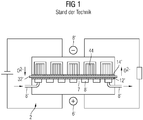
- FIG. 1 which belongs to the prior art
- a solid electrolyte metal-air battery Rechargeable Oxide Battery (ROB)
- a common structure of a ROB is that at a positive electrode 12 ', which is also referred to as an air electrode, a process gas, in particular air, is blown via a gas supply 8', wherein during the discharge (circuit on the right side of the image) of the air oxygen is withdrawn.
- the oxygen passes in the form of oxygen ions O 2- through a voltage applied to the positive electrode solid electrolyte 32 '(electrolyte layer), to a negative electrode 14'.
- This is connected via a gaseous redox pair, for example a hydrogen-steam mixture with the porous storage medium in combination. If a dense layer of the active storage material were present at the negative electrode 14 ', the charging capacity of the battery would be quickly exhausted.
- a storage structure 2 of porous material on the negative electrode as the energy storage medium, which contains a functionally effective oxidizable material as a storage medium 44 ', preferably in the form of iron and iron oxide.
- the metal or the metal oxide iron / iron oxide
- This mechanism of oxygen transport via a redox pair is called a shuttle mechanism.
- iron as an oxidizable material, ie as storage medium 44 ', is that it has approximately the same rest voltage of about 1 V in its oxidation process, such as the redox couple H 2 / H 2 O at a partial pressure ratio of 1, otherwise results an increased resistance to oxygen transport through the diffusing components of this redox couple.
- this temperature range is advantageous.
- the active storage material tends to sinter, meaning that the individual grains are increasingly merging with each other through diffusion processes, the reactive surface area decreases, and the continuously open pore structure required for gas transport disappears.
- the redox pair H 2 / H 2 O can no longer reach the active surface of the storage medium 44 ', so that after a partial discharge of the memory, the internal resistance of the battery becomes very high, which prevents further technically meaningful discharge.
- ROB Reliable and Low-power
- FIG. 1 With respect to the positive electrode 12 ', the electrolyte structure 32' and the negative electrode 14 ', only a very simplified schematic is given. In the prior art, this is usually a layer structure which has a ceramic substrate which, for example, is based on yttrium-reinforced zirconium oxide. This very brittle substrate must be electrically contacted both on the positive side 6 'and on the negative side 8' of the energy converter cell. On the negative side 8 ', the contacting takes place, for example, via an electrically conductive network, not shown here, which is inserted between the negative electrode 14' and the storage medium 44 '.
- This contacting method involves a multiple statically indeterminate mechanical load which acts on the electrode structure, moreover, it is a contacting structure that is only in the assembled state the energy converter cell, here in the form of the metal-air battery, is electrically testable.
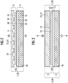
- an electrochemical converter unit 4 (referred to below as the converter unit 4) is presented, which has a porous metallic framework as a self-supporting substrate 16, which is part of a negative electrode 14.
- This porous ceramic framework that forms the substrate 16 may be configured, for example, in the form of a metallic foam.
- the material is for example a nickel-based alloy or iron-based alloy, which are largely inert at the described high process temperatures of the metal-air battery.
- a functional layer 30 of the negative electrode 14 is applied.
- the functional layer 30 together with the substrate 16 forms the negative electrode 14.
- This layer 30 is followed by an electrolyte layer 32 which contains a solid electrolyte based on yttrium-reinforced zirconium oxide.
- a diffusion barrier layer 36 is provided, which is arranged between the electrolyte layer 32 and a functional layer 34 of the positive electrode 12.
- a contact layer 18 is applied, which makes contact with a self-supporting layer 20 of the positive electrode 12.
- the self-supporting layer 20 it is a monolithic metallic structure, for example in the form of a metallic sheet. If necessary, this self-supporting layer 20 may be surrounded by a protective layer 22, which serves in particular as an oxidation protection layer.
- the self-supporting layer 20, possibly its protective layer 22, the contacting layer 18 and the functional layer 34 of the positive electrode 12 together form the positive electrode 12 according to this representation.
- the self-supporting layer 26 is formed so that channels form the part the process gas supply 8 are. Through these channels, the oxygen reaches the functional layer of the positive electrode 12 and on via the electrolyte layer 32 to the negative electrode 14, as already described in the introduction.
- the functional layer 34 of the positive electrode 12, the electrolyte layer 32, the diffusion layer 36 and the functional layer 30 of the negative electrode 14 together form the above-mentioned functional layers, which in themselves each have a relatively small thickness, usually between 10 .mu.m and 50 .mu.m is. Since these layers are not self-supporting per se, they are applied to the self-supporting substrate 16.
- This metallic, porous, electrically conductive self-supporting substrate 16 differs from the prior art in that there is used in each case a ceramic-based, non-electrically conductive monolithic substrate. As a result of the construction described, the electrodes can flow off flat through the substrate 16 and be fed into a circuit through a lateral current drain 46.
- the structure according to FIG. 3 differs from the structure FIG. 2 merely in that as a self-supporting layer 20 of the positive electrode, a porous metallic body 24 is used, which may in principle have similar properties as the substrate 16 of the negative electrode.
- This porous metallic body 24 is different than the monolithic metallic body 26 according to FIG. 2 , permeable to air, which leads to the fact that the channels of the air supply 8 can be dispensed with.
- the porous metallic body 24 can thus be applied continuously to the contact layer 18, recesses in the form of channels are not necessary here.
- FIGS. 2 and 3 Shown sheet-like structure of the individual functional layers and substrates, which together form the cohesively connected electrochemical transducer unit 4, can also be referred to as multi-layer stack 38.
- This multilayer stack 38 can be designed so that different layers, exemplified here the contacting layer 18, the diffusion layer 36 and the functional layer 34 of the positive electrode 12 possibly also regions of the self-supporting layer 20 and the substrate 16 of a smaller area more expansion than the usual layers, resulting in that a circumferential groove 40 is formed, which is particularly suitable to insert a seal 42 there.
- FIG. 4 is an installation position of a multi-layer stack 38 from the FIGS. 2 or 3 represented in an energy converter cell 2, in particular a cell of a metal-air battery.
- This cell 2 in this case has housing plates 50 and 50 '(also interconnector plates), which have corresponding recesses for the electrochemical transducer unit 4, also a storage medium 44 are housed in these recesses, and will not be discussed in detail on the exact arrangement at this point , However, it should be discussed here on the arrangement of the seal 42, which is inserted on the one hand between the housing parts 50 and 50 'of the cell 2, and in turn protrudes into the groove 40 of the converter unit.
- the transducer unit 4 is thus supported by the inserted in the groove 40 seal 42, which is advantageous to mention that hardly any mechanical stresses act on the transducer unit 4, is ensured by the already described in accordance with Figure 2 and 3 lateral contact 46 with the housing part 50 and 50 '. It can thus be a substantial mechanical decoupling of the MEA of the cell 2 at the same time good contact.
- FIG. 5 is an enlarged view of the section V in FIG. 4 given where the arrangement of the seal 42 can be seen more clearly, as it protrudes into the groove 40 of the converter unit 4. Possibly. could still be a joint 48, for example, a weld or a solder joint between the transducer unit 4 and the housing part 50, 50 'may be provided.
Landscapes
- Chemical & Material Sciences (AREA)
- Chemical Kinetics & Catalysis (AREA)
- Electrochemistry (AREA)
- General Chemical & Material Sciences (AREA)
- Engineering & Computer Science (AREA)
- Manufacturing & Machinery (AREA)
- Life Sciences & Earth Sciences (AREA)
- Sustainable Development (AREA)
- Sustainable Energy (AREA)
- Composite Materials (AREA)
- Ceramic Engineering (AREA)
- Hybrid Cells (AREA)
Description
- Wiederaufladebare Festelektrolyt-Metall-Luft-Batterien aber auch Brennstoffzellen des Typs SOFC weisen keramische Grundelemente wie eine Zirkonoxid-Elektrolytschicht sowie Oxidkeramiken als Kathoden und Anoden bzw. als positive oder negative Elektroden auf. Der Verbund aus oxidkeramischen Elektroden sowie Festkörperelektrolyten wird dabei als sogenannte Membran-Elektroden-Einheiten (englisch: membrane electrode assembly, MEA) bezeichnet und ermöglicht die Umwandlung von elektrische in chemischer Energie sowie umgekehrt. Zur Speicherung der Energie dient in der genannten Festelektrolyt-Metall-Luft-Batterie ein Redoxpaar aus Metall und Metalloxid wie beispielsweise Eisen und Eisenoxid in verschiedenen Oxidationsstufen bzw. Nickel und Nickeloxid. Hierbei wird der Sauerstoff über ein gasförmiges Redoxpaar, im einfachsten Fall H2/H20, von der negativen Elektrode zur Oberfläche des Speichermediums gebracht. Ein grundlegendes Problem solcher beschriebener Batterien aber auch in anderen Energiewandlerzellen, die auf der eher spröde oxidkeramische MEA Strukturen zurückgreifen, stellt sich jeweils die elektrische Kontaktierung dieser MEAs dar, da die oxidkeramische Elektrolytschicht nur geringe Leit-und Stromtragfähigkeiten besitzt. Zudem sind derartige MEA Strukturen relativ spröde, wobei es beim Zusammenbau von mehreren Energiewandlerzellen zu Stacks bei kleinen Fertigungstoleranzen zu hohen inneren Spannungen in der MEA kommen kann. Der beschriebene Aufbau ist bezüglich seiner elektrischen Eigenschaften jedoch nur im zusammengebauten Zustand elektrisch prüfbar.
- Die Aufgabe der Erfindung besteht darin, eine Energiewandlerzelle, insbesondere eine Energiespeicherzelle bereitzustellen, die gegenüber dem Stand der Technik einen reduzierten Fertigungsaufwand aufweist, wobei eine lastfreie Montage der MEA möglich ist, die wiederum vor der Montage auf ihre elektrischen Eigenschaften geprüft werden kann.
- Die Lösung der Aufgabe besteht in einer Energiewandlerzelle mit einer elektrochemischen Wandlereinheit nach Anspruch 1.
- Die erfindungsgemäße Energiewandlerzelle mit einer elektrochemischen Wandlereinheit weist eine elektrisch positive Seite mit einer Prozessgaszufuhr sowie einer elektrisch negativen Seite auf. Zwischen den beiden Seiten ist die elektromechanische Wandlereinheit angeordnet. Diese elektrochemische Wandlereinheit weist ein selbsttragendes Substrat und mehrere funktionale Schichten auf. Die Wandlereinheit zeichnet sich dadurch aus, dass sie eine positive Elektrode und negative Elektrode aufweist und dass die negative Elektrode ein poröses, metallisches selbsttragendes Substrat umfasst.
- Die hier beschriebene Wandlereinheit geht in ihren Grundzügen auf die bereits beschriebene Membranelektrodeneinheit (MEA) zurück, sie unterscheidet sich von üblichen MEAs jedoch im Wesentlichen darin, dass das selbsttragende Substrat, das auch eine MEA aufweist, in diesem Fall durch einen porösen, metallischen, selbsttragenden Körper gebildet wird. Als Material hierfür hat sich insbesondere eine Eisenbasislegierung oder eine Nickelbasislegierung als zweckmäßig erwiesen. Andere Legierungen die entsprechend temperatur- und oxidationsbeständig sind können ebenfalls eingesetzt werden. Hierbei handelt es sich um eine tragende Struktur, also ein selbsttragendes Substrat, das gleichzeitig elektrisch leitfähig ist, was dazu führt, dass eine Kontaktierung der MEA, wie dies im Stand der Technik notwendig ist, entfällt. Die Elektronen werden durch das poröse metallische selbsttragende Substrat lateral abgeführt und seitlich durch eine laterale Stromableitung in einen Stromkreis eingeführt. Es handelt sich hierbei also um eine Integration der Stromableitung in eine Membran-Elektroden-Einheit.
- Die elektrochemische Wandlereinheit weist, anders als eine herkömmliche MEA, somit gleichzeitig eine integrierte Kontaktierung auf, so dass auch vor dem Zusammenbau der gesamten Energiewandlerzelle die Kontaktierungsgüte und die elektrischen Eigenschaften der Wandlereinheit getestet werden kann. Da die Kontaktierung in diesem Aufbau nicht durch unflexible Gehäuseteile der Energiewandlerzelle erfolgen muss, ist ferner eine lastfreie Montage der Wandlereinheit möglich. Zudem wird die Sprödigkeit der Wandlereinheit gegenüber einer herkömmlichen MEA insofern reduziert, dass als tragendes Substrat für die weiteren funktionalen Schichten ein metallisches Substrat anwendbar ist, dass gegenüber den herkömmlichen keramischen orientierten Substraten eine höhere Duktilität aufweist.
- In einer weiteren Ausgestaltungsform der Erfindung weist die positive Elektrode eine Kontaktschicht auf, mit der Kontakt zu einer selbsttragenden elektrisch leitfähigen Schicht hergestellt wird. Es hat sich als zweckmäßig herausgestellt, dass nicht nur die negative Elektrode ein selbsttragendes Substrat umfasst sondern dass dies auch dann einen Vorteil bringt, wenn die positive Elektrode eine selbsttragende Schicht, die monolithisch beispielsweise in Form eines Blechs ausgestaltet sein kann, die aber auch ebenfalls wie bei der negativen Elektrode in Form eines porösen metallischen Materials ausgestaltet sein kann, versehen ist. Somit kann auch über die positive Elektrode ein lateraler Abfluss der Elektronen erfolgen, wobei die Kontaktierung mit dem Stromkreis seitlich von der flächig ausgestalteten Wandlereinheit erfolgen kann.
- Dabei kann es zweckmäßig sein, dass die selbsttragende elektrische leitfähige Schicht der positiven Elektrode mit einer zusätzlichen Schutzschicht gegen Oxidation versehen ist. Ferner ist es zweckmäßig, dass das selbsttragende Substrat der negativen Elektrode und die funktionalen Schichten sowie ggf. die selbsttragende Schicht der positiven Elektrode stoffschlüssig miteinander verbunden sind. Somit bilden die Substrate um die erwähnten Schichten eine geschlossene, stoffschlüssige Einheit, die grundsätzlich vor dem Einbau in eine Energiewandlerzelle auf elektrische und mechanische Fähigkeiten geprüft werden kann.
- Die elektrochemische Wandlereinheit weist bevorzugt einen Schichtverbund auf, der wie folgt ausgestaltet ist. Auf dem porösen metallischen selbsttragenden Substrat sind folgende funktionale Schichten in der angegebenen Reihenfolge angeordnet: Zunächst folgt eine Funktionsschicht der negativen Elektrode, einer Elektrolytschicht, insbesondere einen Festkörperelektrolyten beispielsweise auf Basis von yttriumverstärkten Zirkonoxid, darauf folgt eine Funktionsschicht der positiven Elektrode sowie die Kontaktschicht und anschließend die selbsttragende elektrische Schicht der positiven Elektrode die, wie bereits erwähnt, in Form eines Bleches, eines Netzes oder auch in Form eines porösen Substrats analog des Substrats in der negativen Elektrode ausgestaltet sein kann. Zwischen der Elektrolytschicht und der Funktionsschicht der positiven Elektrode ist auch noch eine Diffusionssperrschicht angeordnet die verhindert, dass Ionen aus der Elektrolytschicht in die Funktionsschicht der positiven Elektrode diffundieren. Die aufgezählte Reihenfolge der Schichten stellt eine vorteilhafte Ausgestaltungsform dar, es können jedoch noch weitere funktionale Schichten, die hier nicht erwähnt sind, zweckmäßig sein. Die Aufzählung hat somit keinen Anspruch auf Vollständigkeit.
- Es hat sich ferner als zweckmäßig herausgestellt, dass ein Mehrlagenstapel, der durch das selbsttragende Substrat sowie durch die funktionalen Schichten und ggf. durch die elektrisch leitfähige selbsttragende Schicht der positiven Elektrode gebildet wird und der wesentlicher Bestandteil der Einheit ist, eine zumindest teilweise umlaufende Nut aufweist, in die bei einer Montage der Wandlereinheit eine Dichtung eingelegt werden kann, die über die beschriebene Nut hinaus übersteht. Diese ist in einer weiteren Nut der Energiewandlerzelle in einer Interkonnektorplatte gelagert, somit wird eine mechanische Belastung der Wandlereinheit reduziert wird.
- Weitere vorteilhafte Ausgestaltungsformen sowie weitere Merkmale der Erfindung werden anhand der folgenden Figuren näher beschrieben, gleiche Merkmale in unterschiedlichen Ausgestaltungsformen werden dabei mit denselben Bezugszeichen versehen. Merkmale aus dem Stand der Technik, die dieselbe Bezeichnung tragen, werden mit demselben Bezugszeichen wie zur Beschreibung der Erfindung versehen, diesen Bezugszeichen wird ein zusätzlicher Strich angehängt.
- Dabei zeigen:
-
Figur 1 den schematischen Aufbau einer Festelektrolyt-Metall-Luft-Batterie, -
Figur 2 eine elektrochemische Wandlereinheit, -
Figur 3 eine elektrochemische Wandlereinheit, -
Figur 4 eine Energiewandlerzelle mit einer elektrochemischen Wandlereinheit in Einbaulauge und -
Figur 5 eine vergrößerte Darstellung des Ausschnittes V inFigur 4 . - Anhand von
Figur 1 (die zum Stand der Technik gehört) soll zunächst schematisch die Wirkungsweise einer Festelektrolyt-Metall-Luft-Batterie (auch Rechargeable Oxide Batterie (ROB)) beschrieben werden, insoweit dies für die vorliegende Beschreibung der Erfindung notwendig ist. Ein üblicher Aufbau einer ROB besteht darin, dass an einer positiven Elektrode 12', die auch als Luftelektrode bezeichnet wird, ein Prozessgas, insbesondere Luft, über eine Gaszufuhr 8' eingeblasen wird, wobei beim Entladen (Stromkreis auf der rechten Bildseite) der Luft Sauerstoff entzogen wird. Der Sauerstoff gelangt in Form von Sauerstoffionen O2- durch einen an der positiven Elektrode anliegenden Feststoffelektrolyten 32' (Elektrolytschicht), zu einer negativen Elektrode 14'. Diese steht über ein gasförmiges Redoxpaar, z.B. ein Wasserstoff-Wasserdampf-Gemisch mit dem porösen Speichermedium in Verbindung. Würde an der negativen Elektrode 14' eine dichte Schicht des aktiven Speichermaterials vorliegen, so würde die Ladekapazität der Batterie schnell erschöpft werden. - Aus diesem Grund ist es zweckmäßig, an der negativen Elektrode als Energiespeichermedium eine Speicherstruktur 2 aus porösem Material einzusetzen, das ein funktional wirkendes oxidierbares Material als ein Speichermedium 44', bevorzugt in Form von Eisen und Eisenoxid enthält.
- Über ein, beim Betriebszustand der Batterie gasförmiges Redoxpaar, beispielsweise H2/H2O, werden die, durch den Festkörperelektrolyten 32' transportierten Sauerstoffionen nach ihrer Entladung an der negativen Elektrode in Form von Wasserdampf durch Porenkanäle des Speichermediums 44', transportiert. Je nachdem, ob ein Entlade- oder Ladevorgang vorliegt, wird das Metall bzw. das Metalloxid (Eisen/Eisenoxid) oxidiert oder reduziert und der hierfür benötigte Sauerstoff durch das gasförmige Redoxpaar H2/H2O angeliefert oder zum Festkörperelektrolyten zurück transportiert. Dieser Mechanismus des Sauerstofftransportes über ein Redoxpaar wird als Shuttlemechanismus bezeichnet.
- Der Vorteil des Eisens als oxidierbares Material, also als Speichermedium 44', besteht darin, dass es bei seinem Oxidationsprozess in etwa dieselbe Ruhespannung von etwa 1 V aufweist, wie das Redoxpaar H2/H2O bei einem Partialdruckverhältnis von 1, andernfalls ergibt sich ein erhöhter Widerstand für den Sauerstofftransport durch die diffundierenden Komponenten dieses Redoxpaares.
- Die Diffusion der Sauerstoffionen durch die Elektrolytschicht 32' benötigt eine hohe Betriebstemperatur von 600 bis 800°C der beschriebenen ROB, aber auch für die optimale Zusammensetzung des Redoxpaares H2/H2O in Gleichgewicht mit dem Speichermaterial ist dieser Temperaturbereich vorteilhaft. Hierbei ist nicht nur die Struktur der Elektroden 12', 14' und die Elektrolytschicht 32' einer hohen thermischen Belastung ausgesetzt, sondern auch das Speichermedium 44'. Bei den stetigen Zyklen von Oxidation und Reduktion neigt das aktive Speichermaterial dazu, zu versintern, das bedeutet, dass die einzelnen Körner immer mehr miteinander durch Diffusionsprozesse verschmelzen, die reaktive Oberfläche sinkt und die für den Gastransport erforderliche durchgehend offene Porenstruktur verschwindet. Bei einer geschlossenen Porenstruktur kann das Redoxpaar H2/H2O die aktive Oberfläche des Speichermedium 44' nicht mehr erreichen, so dass bereits nach einer Teilentladung des Speichers der Innenwiderstand der Batterie sehr hoch wird, was eine weitere technisch sinnvolle Entladung verhindert.
- Ein Vorteil der ROB besteht darin, dass sie durch ihre kleinste Einheit, nämlich die Speicherzelle modular nahezu unbegrenzt erweiterbar ist. Somit ist eine kleine Batterie für den stationären Hausgebrauch ebenso darstellbar wie eine großtechnische Anlage zur Speicherung der Energie eines Kraftwerkes.
- In
Figur 1 ist bezüglich der positiven Elektrode 12', der Elektrolytstruktur 32' und der negativen Elektrode 14' lediglich eine sehr vereinfachte schematische Darstellung angegeben. Üblicherweise handelt es sich hierbei im Stand der Technik um eine Schichtstruktur, die ein keramisches Substrat aufweist, das beispielsweise auf der Basis von yttriumverstärkten Zirkonoxid besteht. Dieses sehr spröde Substrat muss sowohl auf der positiven Seite 6' als auch auf der negativen Seite 8' der Energiewandlerzelle elektrisch kontaktiert werden. Auf der negativen Seite 8' erfolgt die Kontaktierung beispielsweise über ein hier nicht dargestelltes elektrisch leitfähiges Netz, das zwischen der negativen Elektrode 14' und dem Speichermedium 44' eingefügt ist. Auf der positiven Seite 6' erfolgt die Kontaktierung durch Stege 7', die Kanäle der Luftzufuhrvorrichtung 8' voneinander trennen. Bei dieser Kontaktierungsmethode handelt es sich um eine mehrfach statisch unbestimmte mechanische Belastung, die auf die Elektrodenstruktur wirkt, zudem handelt es sich um eine Kontaktierungsstruktur die erst im zusammengebauten Zustand der Energiewandlerzelle, hier im Form der Metall-Luft-Batterie, elektrisch testbar ist. - Zur Vermeidung dieser beiden wesentlichen Nachteile wird nach
Figur 2 beispielhaft eine elektrochemische Wandlereinheit 4 (im nachfolgenden Wandlereinheit 4 genannt) vorgestellt die als selbsttragendes Substrat 16, das Bestandteil einer negativen Elektrode 14 ist, ein poröses metallisches Gerüst aufweist. Dieses poröse keramische Gerüst das das Substrat 16 bildet, kann beispielsweise in Form eines metallischen Schaumes ausgestaltet sein. Hierbei bietet sich als Material beispielsweise eine Nickelbasislegierung oder Eisenbasislegierung an, die bei den beschriebenen hohen Prozesstemperaturen der Metall-Luft-Batterie weitgehend inert sind. - Auf diesem Substrat 16 ist eine Funktionsschicht 30 der negativen Elektrode 14 aufgebracht. Die Funktionsschicht 30 zusammen mit dem Substrat 16 bildet die negative Elektrode 14. Auf dieser Schicht 30 folgt eine Elektrolytschicht 32, die einen Feststoffelektrolyten auf der Basis von yttriumverstärkten Zirkonoxid enthält. Zur Vermeidung der Diffusion von Ionen aus der Elektrolytschicht ist eine Diffusionssperrschicht 36 vorgesehen, die zwischen der Elektrolytschicht 32 und einer Funktionsschicht 34 der positiven Elektrode 12 angeordnet ist. Auf diese Funktionsschicht 34 der positiven Elektrode 12 ist eine Kontaktschicht 18 aufgebracht, die den Kontakt zu einer selbsttragenden Schicht 20 der positiven Elektrode 12 herstellt. Bei der selbsttragenden Schicht 20 gemäß
Figur 2 handelt es sich um eine monolithische metallische Struktur, beispielsweise in Form eines metallischen Blechs. Diese selbsttragende Schicht 20 kann ggf. von einer Schutzschicht 22, die insbesondere als Oxidationsschutzschicht dient, umgeben sein. - Die selbsttragende Schicht 20, ggf. deren Schutzschicht 22, die Kontaktierungsschicht 18 sowie die Funktionsschicht 34 der positiven Elektrode 12 bilden zusammen nach dieser Darstellung die positive Elektrode 12. Bei dieser Ausgestaltungsform ist die selbsttragende Schicht 26 so ausgebildet, dass sich Kanäle bilden, die Teil der Prozessgaszufuhr 8 sind. Durch diese Kanäle gelangt der Sauerstoff an die funktionale Schicht der positiven Elektrode 12 und weiter über die Elektrolytschicht 32 zur negativen Elektrode 14, wie dies bereits einleitend beschrieben ist.
- Die Funktionsschicht 34 der positiven Elektrode 12, die Elektrolytschicht 32, die Diffusionsschicht 36 sowie die Funktionsschicht 30 der negativen Elektrode 14 bilden zusammen die bereits erwähnten funktionalen Schichten, die für sich genommen jeweils eine relativ geringe Dicke aufweist, die üblicherweise zwischen 10 µm und 50 µm beträgt. Da diese Schichten für sich nicht selbsttragend sind, sind sie auf das selbsttragende Substrat 16 aufgebracht. Dieses metallische, poröse, elektrisch leitfähige selbsttragende Substrat 16 unterscheidet sich vom Stand der Technik darin, dass dort jeweils ein keramisch basiertes, nicht elektrisch leitfähiges monolithisches Substrat verwendet wird. Durch den beschriebenen Aufbau können die Elektroden flächig durch das Substrat 16 abfließen und durch eine laterale Stromableitung 46 in einen Stromkreis eingespeist werden.
- Der Aufbau gemäß
Figur 3 unterscheidet sich vom Aufbau nachFigur 2 lediglich darin, dass als selbsttragende Schicht 20 der positiven Elektrode ein poröser metallischer Körper 24 eingesetzt wird, der grundsätzlich ähnliche Eigenschaften wie das Substrat 16 der negativen Elektrode aufweisen kann. Dieser poröse metallische Körper 24 ist anders, als der monolithisch metallische Körper 26 gemäßFigur 2 , luftdurchlässig, was dazu führt, dass auf die Kanäle der Luftzufuhr 8 verzichtet werden kann. Der poröse metallische Körper 24 kann somit auf die Kontaktschicht 18 durchgehend aufgebracht werden, Aussparungen in Form von Kanälen sind hier nicht notwendig. - Der in den
Figuren 2 und 3 gezeigter schichtförmige Aufbau der einzelnen funktionellen Schichten sowie Substraten, die zusammen die stoffschlüssig verbundene elektrochemische Wandlereinheit 4 bilden, kann auch als Mehrlagenstapel 38 bezeichnet werden. Dieser Mehrlagenstapel 38 kann so ausgestaltet sein, dass verschiedene Schichten, hier exemplarisch dargestellt die Kontaktierungsschicht 18, die Diffusionsschicht 36 sowie die Funktionsschicht 34 der positiven Elektrode 12 ggf. auch Bereiche der selbsttragenden Schicht 20 sowie das Substrat 16 einer kleineren Fläche die mehr Ausdehnung aufweisen als die üblichen Schichten, was dazu führt, dass eine umlaufende Nut 40 entsteht, die insbesondere dazu geeignet ist, dort eine Dichtung 42 einzufügen. - In
Figur 4 ist eine Einbaulage eines Mehrlagenstapels 38 aus denFiguren 2 oder 3 in einer Energiewandlerzelle 2, insbesondere einer Zelle einer Metall-Luft-Batterie dargestellt. Diese Zelle 2 weist dabei Gehäuseplatten 50 und 50' (auch Interkonnektorplatten) auf, die entsprechende Aussparungen für die elektrochemische Wandlereinheit 4 aufweisen, ferner sind in diesen Aussparungen auch noch ein Speichermedium 44 untergebracht, wobei auf die genaue Anordnung an dieser Stelle nicht näher eingegangen wird. Es soll jedoch hier auf die Anordnung der Dichtung 42 eingegangen werden, die einerseits zwischen den Gehäuseteilen 50 und 50' der Zelle 2 eingelegt ist, und die wiederrum in die Nut 40 der Wandlereinheit hineinragt. Die Wandlereinheit 4 wird somit durch die in der Nut 40 eingelegte Dichtung 42 getragen, wobei hierbei als vorteilhaft zu erwähnen ist, dass kaum mechanische Spannungen auf die Wandlereinheit 4 wirken, durch die bereits gemäß Figur 2 und 3 beschriebene laterale Kontaktierung 46 mit dem Gehäuseteil 50 und 50', gewährleistet ist. Es kann somit eine weitgehende mechanische Entkopplung der MEA von der Zelle 2 bei gleichzeitig guter Kontaktierung erfolgen. InFigur 5 ist eine vergrößerte Darstellung des Ausschnittes V inFigur 4 gegeben, wo die Anordnung der Dichtung 42 deutlicher zu erkennen ist, wie sie in die Nut 40 der Wandlereinheit 4 hineinragt. Ggf. könnten noch eine Fügestelle 48, beispielsweise eine Schweißnaht oder eine Lotverbindung zwischen der Wandlereinheit 4 und dem Gehäuseteil 50, 50' vorgesehen sein. - Neben der bereits erwähnten separaten Prüffähigkeit der integrierten Wandlereinheit 4, die sich insbesondere auf die Kontaktierungsgüte der Einzelkomponenten bezieht und der lastfreie Montage die zu einer deutlich verbesserten mechanischen Stabilität des Gesamtaufbaus führt, sei auch noch erwähnt, dass durch die beschriebene Zelle und die beschriebene Wandlereinheit 4 der Fertigungsaufwand eines Stacks, der aus verschiedenen Zellen 2 besteht, sehr stark reduziert wird. Dies wiederum führt zu einem deutlich einfacheren Design der Gehäuseteile 50, 50' also den sogenannten Interconnectorplatten. Dadurch wird das Volumen, das für das Speichermedium 44 zur Verfügung steht, vergrößert, was wiederum zu einer höheren Energiedichte sowie der Verringerung der Kosten pro Stack führt.
Claims (8)
- Energiewandlerzelle (2) mit einer elektrochemischen Wandlereinheit (4), wobei die Energiewandlerzelle (2) eine elektrisch positive Seite (6) mit einer Prozessgaszufuhr (8) und eine elektrisch negative Seite (10) umfasst und zwischen den beiden Seiten die elektrochemische Wandlereinheit (4) angeordnet ist, die ein selbsttragendes Substrat und mehrere funktionale Schichten (28) aufweist, dadurch gekennzeichnet, dass die elektrochemische Wandlereinheit (4) eine positive Elektrode (12) und eine negative Elektrode (14) aufweist und dass die negative Elektrode (14) ein poröses metallische selbstragendes Substrat (16) umfasst und dass die elektrochemische Wandlereinheit (4) einen Schichtfolgeverbund aufweist, der auf dem porösen metallischen selbstragenden Substrat (16) noch folgende funktionale Schichten (28) in der angegebenen Reihenfolge umfasst: eine Funktionsschicht (30) der negativen Elektrode (14), eine Elektrolytschicht (32), eine Funktionsschicht (34) der positiven Elektrode (12), die Kontaktschicht(18) und die selbsttragende elektrisch leitfähige Schicht (20) der positiven Elektrode (12), wobei zwischen der Elektrolytschicht (32) und er Funktionsschicht (34) der positiven Elektrode (12) eine Diffusionssperrschicht (30) angeordnet ist.
- Energiewandlerzelle nach Anspruch 1, dadurch gekennzeichnet, dass die positive Elektrode (12) eine Kontaktschicht (18) und eine selbsttragende elektrisch leitfähige Schicht (20) umfasst.
- Energiewandlerzelle nach Anspruch 2, dadurch gekennzeichnet, dass die selbsttragende Schicht (20) der positiven Elektrode (12) eine Schutzschicht (22) aufweist,
- Energiewandlerzelle nach Anspruch 2 oder 3, dadurch gekennzeichnet, dass die selbsttragende Schicht (20) der positiven Elektrode (12) einen porösen metallischen Körper (24) umfasst.
- Energiewandlerzelle nach Anspruch 2 oder 3, dadurch gekennzeichnet, dass die selbsttragende Schicht (20) der positiven Elektrode (12) einen flächigen monolithischen metallischen Körper (26) umfasst.
- Energiewandlerzelle nach einem der vorhergehenden Ansprüchen, dadurch gekennzeichnet, dass das selbsttragende Substrat (16) und die funktionalen Schichten (18) stoffschlüssig miteinander verbunden sind.
- Energiewandlerzelle nach einem der vorhergehenden Ansprüchen, dadurch gekennzeichnet, dass das selbsttragende Substrat(16) und die funktionalen Schichten (28) sowie die selbsttragende Schicht (20) zu einem Mehrlagenstapel (38) flächig übereinander angeordnet sind dadurch gekennzeichnet, dass der Mehrlagenstapel (38) mindestens teilweise eine umlaufende Nut (40) aufweist.
- Energiewandlerzelle nach einem der vorhergehenden Ansprüchen, dadurch gekennzeichnet, dass das poröse metallische selbstragende Substrat (16) der negativen Elektrode (14) aus einer Eisenbasis-Legierung oder einer Nickelbasis-Legierung besteht.
Applications Claiming Priority (2)
| Application Number | Priority Date | Filing Date | Title |
|---|---|---|---|
| DE201310205407 DE102013205407A1 (de) | 2013-03-27 | 2013-03-27 | Energiewandlerzelle mit elektrochemischer Wandlereinheit |
| PCT/EP2014/053523 WO2014154406A1 (de) | 2013-03-27 | 2014-02-24 | Energiewandlerzelle mit elektrochemischer wandlereinheit |
Publications (2)
| Publication Number | Publication Date |
|---|---|
| EP2956981A1 EP2956981A1 (de) | 2015-12-23 |
| EP2956981B1 true EP2956981B1 (de) | 2017-11-01 |
Family
ID=50193465
Family Applications (1)
| Application Number | Title | Priority Date | Filing Date |
|---|---|---|---|
| EP14707711.9A Active EP2956981B1 (de) | 2013-03-27 | 2014-02-24 | Energiewandlerzelle mit elektrochemischer wandlereinheit |
Country Status (5)
| Country | Link |
|---|---|
| US (1) | US9929452B2 (de) |
| EP (1) | EP2956981B1 (de) |
| DE (1) | DE102013205407A1 (de) |
| ES (1) | ES2657977T3 (de) |
| WO (1) | WO2014154406A1 (de) |
Cited By (1)
| Publication number | Priority date | Publication date | Assignee | Title |
|---|---|---|---|---|
| WO2021078919A1 (en) | 2019-10-24 | 2021-04-29 | Siemens Energy Global GmbH & Co. KG | Power plant system and method of operating the same |
Families Citing this family (6)
| Publication number | Priority date | Publication date | Assignee | Title |
|---|---|---|---|---|
| DE102013205407A1 (de) | 2013-03-27 | 2014-10-16 | Siemens Aktiengesellschaft | Energiewandlerzelle mit elektrochemischer Wandlereinheit |
| BR112019008041A2 (pt) | 2016-10-21 | 2019-07-02 | Nantenergy Inc | elétrodo de combustível corrugado |
| WO2019133702A1 (en) | 2017-12-29 | 2019-07-04 | Staq Energy, Inc. | Long life sealed alkaline secondary batteries |
| MA53343A (fr) | 2018-07-27 | 2022-03-23 | Form Energy Inc | Électrodes négatives pour cellules électrochimiques |
| US12294086B2 (en) | 2019-07-26 | 2025-05-06 | Form Energy, Inc. | Low cost metal electrodes |
| WO2021216769A1 (en) * | 2020-04-22 | 2021-10-28 | Form Energy, Inc. | Porous materials for battery electrodes |
Family Cites Families (6)
| Publication number | Priority date | Publication date | Assignee | Title |
|---|---|---|---|---|
| US6905794B2 (en) * | 2000-08-22 | 2005-06-14 | Hitachi Maxell, Ltd. | Air-hydrogen battery |
| US8802304B2 (en) * | 2010-08-10 | 2014-08-12 | Eos Energy Storage, Llc | Bifunctional (rechargeable) air electrodes comprising a corrosion-resistant outer layer and conductive inner layer |
| US20120058396A1 (en) * | 2010-09-07 | 2012-03-08 | Chun Lu | Oxidation-resistant metal supported rechargeable oxide-ion battery cells and methods to produce the same |
| US8911895B2 (en) * | 2011-04-21 | 2014-12-16 | Siemens Aktiengesellschaft | All solid state rechargeable oxide-ion battery (ROB) system |
| US8685288B2 (en) * | 2012-01-10 | 2014-04-01 | Siemens Aktiengesellschaft | Solid-solution method for producing iron-containing active materials for rechargeable oxide-ion battery cells |
| DE102013205407A1 (de) | 2013-03-27 | 2014-10-16 | Siemens Aktiengesellschaft | Energiewandlerzelle mit elektrochemischer Wandlereinheit |
-
2013
- 2013-03-27 DE DE201310205407 patent/DE102013205407A1/de not_active Withdrawn
-
2014
- 2014-02-24 EP EP14707711.9A patent/EP2956981B1/de active Active
- 2014-02-24 ES ES14707711.9T patent/ES2657977T3/es active Active
- 2014-02-24 US US14/779,933 patent/US9929452B2/en active Active
- 2014-02-24 WO PCT/EP2014/053523 patent/WO2014154406A1/de not_active Ceased
Non-Patent Citations (1)
| Title |
|---|
| None * |
Cited By (1)
| Publication number | Priority date | Publication date | Assignee | Title |
|---|---|---|---|---|
| WO2021078919A1 (en) | 2019-10-24 | 2021-04-29 | Siemens Energy Global GmbH & Co. KG | Power plant system and method of operating the same |
Also Published As
| Publication number | Publication date |
|---|---|
| US9929452B2 (en) | 2018-03-27 |
| WO2014154406A1 (de) | 2014-10-02 |
| US20160056518A1 (en) | 2016-02-25 |
| DE102013205407A1 (de) | 2014-10-16 |
| ES2657977T3 (es) | 2018-03-07 |
| EP2956981A1 (de) | 2015-12-23 |
Similar Documents
| Publication | Publication Date | Title |
|---|---|---|
| EP2956981B1 (de) | Energiewandlerzelle mit elektrochemischer wandlereinheit | |
| DE102021109158A1 (de) | Elektrochemischer Reaktionszellenstapel | |
| DE102022121234A1 (de) | Elektrochemischer Reaktionszellenstapel | |
| DE102009003074A1 (de) | Elektrochemische Zelle zur Gewinnung elektrischer Energie | |
| JP6734723B2 (ja) | 電気化学反応単セル、および、電気化学反応セルスタック | |
| WO2018165682A1 (de) | Poröses formteil für elektrochemisches modul | |
| DE102016210868A1 (de) | Elektrochemische Reaktionseinheit und Brennstoffzellenstapel | |
| DE202013012667U1 (de) | Zelle, Zellenstapeleinheit, elektrochemisches Modul und elektrochemisches Gerät | |
| DE102020209081A1 (de) | Elektrochemischer Reaktionszellenstapel | |
| EP1844513B1 (de) | Interkonnektor für hochtemperaturbrennstoffzellen | |
| EP3014685B1 (de) | Hochtemperaturzelle mit poröser gasführungskanalschicht | |
| DE102021112993A1 (de) | Elektrochemischer Reaktionszellenstapel | |
| DE102015207552A1 (de) | Sauerstoff-Kathode mit schwammartiger Kohlenstoffgerüststruktur | |
| EP1915793A1 (de) | Schutz anodengestützter hochtemperaturbrennstoffzellen gegen reoxidation der anode | |
| DE102010063254A1 (de) | Membran-Elektroden-Anordnung mit zwei Deckschichten | |
| DE102021117551A1 (de) | Elektrochemischer Reaktionszellenstapel | |
| EP2850687B1 (de) | Elektrischer energiespeicher | |
| DE102007021462B3 (de) | Kühlkörper für Brennstoffzellen | |
| DE102012211322A1 (de) | Elektrischer Energiespeicher | |
| AT16121U1 (de) | Stromübertragungssystem | |
| DE102021131474A1 (de) | Elektrochemische Reaktionseinzelzelle und elektrochemischer Reaktionszellenstapel | |
| DE112019007178T5 (de) | Elektrochemischer Reaktionszellenstapel | |
| DE102017100738A1 (de) | Brennstoffzellenstapel mit erhöhter Beständigkeit gegenüber Spannungsumkehr sowie Brennstoffzellensystem und Fahrzeug mit einem solchen | |
| DE102024204981A1 (de) | Elektrochemische Zelleneinheit | |
| DE102005059708A1 (de) | Reoxidationsstabile Hochtemperatur-Brennstoffzelle |
Legal Events
| Date | Code | Title | Description |
|---|---|---|---|
| PUAI | Public reference made under article 153(3) epc to a published international application that has entered the european phase |
Free format text: ORIGINAL CODE: 0009012 |
|
| 17P | Request for examination filed |
Effective date: 20150917 |
|
| AK | Designated contracting states |
Kind code of ref document: A1 Designated state(s): AL AT BE BG CH CY CZ DE DK EE ES FI FR GB GR HR HU IE IS IT LI LT LU LV MC MK MT NL NO PL PT RO RS SE SI SK SM TR |
|
| AX | Request for extension of the european patent |
Extension state: BA ME |
|
| DAX | Request for extension of the european patent (deleted) | ||
| REG | Reference to a national code |
Ref country code: DE Ref legal event code: R079 Ref document number: 502014006046 Country of ref document: DE Free format text: PREVIOUS MAIN CLASS: H01M0008100000 Ipc: H01M0008121300 |
|
| GRAP | Despatch of communication of intention to grant a patent |
Free format text: ORIGINAL CODE: EPIDOSNIGR1 |
|
| RIC1 | Information provided on ipc code assigned before grant |
Ipc: H01M 4/86 20060101ALI20170421BHEP Ipc: H01M 8/1213 20160101AFI20170421BHEP Ipc: H01M 12/08 20060101ALI20170421BHEP Ipc: H01M 4/90 20060101ALI20170421BHEP Ipc: H01M 12/06 20060101ALI20170421BHEP Ipc: H01M 8/0245 20160101ALI20170421BHEP Ipc: H01M 8/0232 20160101ALI20170421BHEP |
|
| INTG | Intention to grant announced |
Effective date: 20170524 |
|
| RAP1 | Party data changed (applicant data changed or rights of an application transferred) |
Owner name: SIEMENS AKTIENGESELLSCHAFT |
|
| GRAS | Grant fee paid |
Free format text: ORIGINAL CODE: EPIDOSNIGR3 |
|
| GRAA | (expected) grant |
Free format text: ORIGINAL CODE: 0009210 |
|
| AK | Designated contracting states |
Kind code of ref document: B1 Designated state(s): AL AT BE BG CH CY CZ DE DK EE ES FI FR GB GR HR HU IE IS IT LI LT LU LV MC MK MT NL NO PL PT RO RS SE SI SK SM TR |
|
| REG | Reference to a national code |
Ref country code: GB Ref legal event code: FG4D Free format text: NOT ENGLISH |
|
| REG | Reference to a national code |
Ref country code: CH Ref legal event code: EP Ref country code: CH Ref legal event code: NV Representative=s name: SIEMENS SCHWEIZ AG, CH Ref country code: AT Ref legal event code: REF Ref document number: 942882 Country of ref document: AT Kind code of ref document: T Effective date: 20171115 |
|
| REG | Reference to a national code |
Ref country code: IE Ref legal event code: FG4D Free format text: LANGUAGE OF EP DOCUMENT: GERMAN |
|
| REG | Reference to a national code |
Ref country code: DE Ref legal event code: R096 Ref document number: 502014006046 Country of ref document: DE |
|
| REG | Reference to a national code |
Ref country code: NL Ref legal event code: FP |
|
| REG | Reference to a national code |
Ref country code: FR Ref legal event code: PLFP Year of fee payment: 5 |
|
| REG | Reference to a national code |
Ref country code: ES Ref legal event code: FG2A Ref document number: 2657977 Country of ref document: ES Kind code of ref document: T3 Effective date: 20180307 |
|
| REG | Reference to a national code |
Ref country code: LT Ref legal event code: MG4D |
|
| PG25 | Lapsed in a contracting state [announced via postgrant information from national office to epo] |
Ref country code: FI Free format text: LAPSE BECAUSE OF FAILURE TO SUBMIT A TRANSLATION OF THE DESCRIPTION OR TO PAY THE FEE WITHIN THE PRESCRIBED TIME-LIMIT Effective date: 20171101 Ref country code: NO Free format text: LAPSE BECAUSE OF FAILURE TO SUBMIT A TRANSLATION OF THE DESCRIPTION OR TO PAY THE FEE WITHIN THE PRESCRIBED TIME-LIMIT Effective date: 20180201 Ref country code: SE Free format text: LAPSE BECAUSE OF FAILURE TO SUBMIT A TRANSLATION OF THE DESCRIPTION OR TO PAY THE FEE WITHIN THE PRESCRIBED TIME-LIMIT Effective date: 20171101 Ref country code: LT Free format text: LAPSE BECAUSE OF FAILURE TO SUBMIT A TRANSLATION OF THE DESCRIPTION OR TO PAY THE FEE WITHIN THE PRESCRIBED TIME-LIMIT Effective date: 20171101 |
|
| PG25 | Lapsed in a contracting state [announced via postgrant information from national office to epo] |
Ref country code: IS Free format text: LAPSE BECAUSE OF FAILURE TO SUBMIT A TRANSLATION OF THE DESCRIPTION OR TO PAY THE FEE WITHIN THE PRESCRIBED TIME-LIMIT Effective date: 20180301 Ref country code: LV Free format text: LAPSE BECAUSE OF FAILURE TO SUBMIT A TRANSLATION OF THE DESCRIPTION OR TO PAY THE FEE WITHIN THE PRESCRIBED TIME-LIMIT Effective date: 20171101 Ref country code: HR Free format text: LAPSE BECAUSE OF FAILURE TO SUBMIT A TRANSLATION OF THE DESCRIPTION OR TO PAY THE FEE WITHIN THE PRESCRIBED TIME-LIMIT Effective date: 20171101 Ref country code: RS Free format text: LAPSE BECAUSE OF FAILURE TO SUBMIT A TRANSLATION OF THE DESCRIPTION OR TO PAY THE FEE WITHIN THE PRESCRIBED TIME-LIMIT Effective date: 20171101 Ref country code: BG Free format text: LAPSE BECAUSE OF FAILURE TO SUBMIT A TRANSLATION OF THE DESCRIPTION OR TO PAY THE FEE WITHIN THE PRESCRIBED TIME-LIMIT Effective date: 20180201 Ref country code: GR Free format text: LAPSE BECAUSE OF FAILURE TO SUBMIT A TRANSLATION OF THE DESCRIPTION OR TO PAY THE FEE WITHIN THE PRESCRIBED TIME-LIMIT Effective date: 20180202 |
|
| PG25 | Lapsed in a contracting state [announced via postgrant information from national office to epo] |
Ref country code: CY Free format text: LAPSE BECAUSE OF FAILURE TO SUBMIT A TRANSLATION OF THE DESCRIPTION OR TO PAY THE FEE WITHIN THE PRESCRIBED TIME-LIMIT Effective date: 20171101 Ref country code: SK Free format text: LAPSE BECAUSE OF FAILURE TO SUBMIT A TRANSLATION OF THE DESCRIPTION OR TO PAY THE FEE WITHIN THE PRESCRIBED TIME-LIMIT Effective date: 20171101 Ref country code: CZ Free format text: LAPSE BECAUSE OF FAILURE TO SUBMIT A TRANSLATION OF THE DESCRIPTION OR TO PAY THE FEE WITHIN THE PRESCRIBED TIME-LIMIT Effective date: 20171101 Ref country code: DK Free format text: LAPSE BECAUSE OF FAILURE TO SUBMIT A TRANSLATION OF THE DESCRIPTION OR TO PAY THE FEE WITHIN THE PRESCRIBED TIME-LIMIT Effective date: 20171101 Ref country code: EE Free format text: LAPSE BECAUSE OF FAILURE TO SUBMIT A TRANSLATION OF THE DESCRIPTION OR TO PAY THE FEE WITHIN THE PRESCRIBED TIME-LIMIT Effective date: 20171101 |
|
| PGFP | Annual fee paid to national office [announced via postgrant information from national office to epo] |
Ref country code: DE Payment date: 20180419 Year of fee payment: 5 Ref country code: CH Payment date: 20180516 Year of fee payment: 5 |
|
| REG | Reference to a national code |
Ref country code: DE Ref legal event code: R097 Ref document number: 502014006046 Country of ref document: DE |
|
| PG25 | Lapsed in a contracting state [announced via postgrant information from national office to epo] |
Ref country code: PL Free format text: LAPSE BECAUSE OF FAILURE TO SUBMIT A TRANSLATION OF THE DESCRIPTION OR TO PAY THE FEE WITHIN THE PRESCRIBED TIME-LIMIT Effective date: 20171101 Ref country code: RO Free format text: LAPSE BECAUSE OF FAILURE TO SUBMIT A TRANSLATION OF THE DESCRIPTION OR TO PAY THE FEE WITHIN THE PRESCRIBED TIME-LIMIT Effective date: 20171101 Ref country code: SM Free format text: LAPSE BECAUSE OF FAILURE TO SUBMIT A TRANSLATION OF THE DESCRIPTION OR TO PAY THE FEE WITHIN THE PRESCRIBED TIME-LIMIT Effective date: 20171101 |
|
| PLBE | No opposition filed within time limit |
Free format text: ORIGINAL CODE: 0009261 |
|
| STAA | Information on the status of an ep patent application or granted ep patent |
Free format text: STATUS: NO OPPOSITION FILED WITHIN TIME LIMIT |
|
| PG25 | Lapsed in a contracting state [announced via postgrant information from national office to epo] |
Ref country code: MT Free format text: LAPSE BECAUSE OF FAILURE TO SUBMIT A TRANSLATION OF THE DESCRIPTION OR TO PAY THE FEE WITHIN THE PRESCRIBED TIME-LIMIT Effective date: 20171101 Ref country code: MC Free format text: LAPSE BECAUSE OF FAILURE TO SUBMIT A TRANSLATION OF THE DESCRIPTION OR TO PAY THE FEE WITHIN THE PRESCRIBED TIME-LIMIT Effective date: 20171101 |
|
| 26N | No opposition filed |
Effective date: 20180802 |
|
| REG | Reference to a national code |
Ref country code: IE Ref legal event code: MM4A |
|
| REG | Reference to a national code |
Ref country code: BE Ref legal event code: MM Effective date: 20180228 |
|
| PG25 | Lapsed in a contracting state [announced via postgrant information from national office to epo] |
Ref country code: SI Free format text: LAPSE BECAUSE OF FAILURE TO SUBMIT A TRANSLATION OF THE DESCRIPTION OR TO PAY THE FEE WITHIN THE PRESCRIBED TIME-LIMIT Effective date: 20171101 Ref country code: LU Free format text: LAPSE BECAUSE OF NON-PAYMENT OF DUE FEES Effective date: 20180224 |
|
| PG25 | Lapsed in a contracting state [announced via postgrant information from national office to epo] |
Ref country code: IE Free format text: LAPSE BECAUSE OF NON-PAYMENT OF DUE FEES Effective date: 20180224 |
|
| PG25 | Lapsed in a contracting state [announced via postgrant information from national office to epo] |
Ref country code: BE Free format text: LAPSE BECAUSE OF NON-PAYMENT OF DUE FEES Effective date: 20180228 |
|
| REG | Reference to a national code |
Ref country code: DE Ref legal event code: R119 Ref document number: 502014006046 Country of ref document: DE |
|
| REG | Reference to a national code |
Ref country code: CH Ref legal event code: PL |
|
| PG25 | Lapsed in a contracting state [announced via postgrant information from national office to epo] |
Ref country code: CH Free format text: LAPSE BECAUSE OF NON-PAYMENT OF DUE FEES Effective date: 20190228 Ref country code: LI Free format text: LAPSE BECAUSE OF NON-PAYMENT OF DUE FEES Effective date: 20190228 |
|
| PG25 | Lapsed in a contracting state [announced via postgrant information from national office to epo] |
Ref country code: DE Free format text: LAPSE BECAUSE OF NON-PAYMENT OF DUE FEES Effective date: 20190903 |
|
| PG25 | Lapsed in a contracting state [announced via postgrant information from national office to epo] |
Ref country code: TR Free format text: LAPSE BECAUSE OF FAILURE TO SUBMIT A TRANSLATION OF THE DESCRIPTION OR TO PAY THE FEE WITHIN THE PRESCRIBED TIME-LIMIT Effective date: 20171101 |
|
| PG25 | Lapsed in a contracting state [announced via postgrant information from national office to epo] |
Ref country code: PT Free format text: LAPSE BECAUSE OF FAILURE TO SUBMIT A TRANSLATION OF THE DESCRIPTION OR TO PAY THE FEE WITHIN THE PRESCRIBED TIME-LIMIT Effective date: 20171101 |
|
| PG25 | Lapsed in a contracting state [announced via postgrant information from national office to epo] |
Ref country code: HU Free format text: LAPSE BECAUSE OF FAILURE TO SUBMIT A TRANSLATION OF THE DESCRIPTION OR TO PAY THE FEE WITHIN THE PRESCRIBED TIME-LIMIT; INVALID AB INITIO Effective date: 20140224 Ref country code: MK Free format text: LAPSE BECAUSE OF NON-PAYMENT OF DUE FEES Effective date: 20171101 |
|
| PG25 | Lapsed in a contracting state [announced via postgrant information from national office to epo] |
Ref country code: AL Free format text: LAPSE BECAUSE OF FAILURE TO SUBMIT A TRANSLATION OF THE DESCRIPTION OR TO PAY THE FEE WITHIN THE PRESCRIBED TIME-LIMIT Effective date: 20171101 |
|
| REG | Reference to a national code |
Ref country code: GB Ref legal event code: 732E Free format text: REGISTERED BETWEEN 20220901 AND 20220907 |
|
| REG | Reference to a national code |
Ref country code: AT Ref legal event code: PC Ref document number: 942882 Country of ref document: AT Kind code of ref document: T Owner name: SIEMENS ENERGY GLOBAL GMBH & CO. KG, DE Effective date: 20221018 |
|
| REG | Reference to a national code |
Ref country code: NL Ref legal event code: PD Owner name: SIEMENS ENERGY GLOBAL GMBH & CO. KG; DE Free format text: DETAILS ASSIGNMENT: CHANGE OF OWNER(S), ASSIGNMENT; FORMER OWNER NAME: SIEMENS AKTIENGESELLSCHAFT Effective date: 20221220 |
|
| REG | Reference to a national code |
Ref country code: ES Ref legal event code: PC2A Owner name: SIEMENS ENERGY GLOBAL GMBH & CO. KG Effective date: 20240403 |
|
| PGFP | Annual fee paid to national office [announced via postgrant information from national office to epo] |
Ref country code: NL Payment date: 20250224 Year of fee payment: 12 |
|
| PGFP | Annual fee paid to national office [announced via postgrant information from national office to epo] |
Ref country code: ES Payment date: 20250314 Year of fee payment: 12 |
|
| PGFP | Annual fee paid to national office [announced via postgrant information from national office to epo] |
Ref country code: AT Payment date: 20250217 Year of fee payment: 12 |
|
| PGFP | Annual fee paid to national office [announced via postgrant information from national office to epo] |
Ref country code: FR Payment date: 20250224 Year of fee payment: 12 |
|
| PGFP | Annual fee paid to national office [announced via postgrant information from national office to epo] |
Ref country code: IT Payment date: 20250225 Year of fee payment: 12 Ref country code: GB Payment date: 20250218 Year of fee payment: 12 |