EP2957005B1 - Nass zusammenpassbare verbindungseinheit für elektrische und/oder optische kabel - Google Patents
Nass zusammenpassbare verbindungseinheit für elektrische und/oder optische kabel Download PDFInfo
- Publication number
- EP2957005B1 EP2957005B1 EP13714343.4A EP13714343A EP2957005B1 EP 2957005 B1 EP2957005 B1 EP 2957005B1 EP 13714343 A EP13714343 A EP 13714343A EP 2957005 B1 EP2957005 B1 EP 2957005B1
- Authority
- EP
- European Patent Office
- Prior art keywords
- case
- connection assembly
- wet mateable
- mateable connection
- gate
- Prior art date
- Legal status (The legal status is an assumption and is not a legal conclusion. Google has not performed a legal analysis and makes no representation as to the accuracy of the status listed.)
- Active
Links
Images




Classifications
-
- H—ELECTRICITY
- H01—ELECTRIC ELEMENTS
- H01R—ELECTRICALLY-CONDUCTIVE CONNECTIONS; STRUCTURAL ASSOCIATIONS OF A PLURALITY OF MUTUALLY-INSULATED ELECTRICAL CONNECTING ELEMENTS; COUPLING DEVICES; CURRENT COLLECTORS
- H01R13/00—Details of coupling devices of the kinds covered by groups H01R12/70 or H01R24/00 - H01R33/00
- H01R13/46—Bases; Cases
- H01R13/52—Dustproof, splashproof, drip-proof, waterproof, or flameproof cases
- H01R13/523—Dustproof, splashproof, drip-proof, waterproof, or flameproof cases for use under water
-
- G—PHYSICS
- G02—OPTICS
- G02B—OPTICAL ELEMENTS, SYSTEMS OR APPARATUS
- G02B6/00—Light guides; Structural details of arrangements comprising light guides and other optical elements, e.g. couplings
- G02B6/24—Coupling light guides
- G02B6/36—Mechanical coupling means
- G02B6/38—Mechanical coupling means having fibre to fibre mating means
- G02B6/3807—Dismountable connectors, i.e. comprising plugs
- G02B6/381—Dismountable connectors, i.e. comprising plugs of the ferrule type, e.g. fibre ends embedded in ferrules, connecting a pair of fibres
- G02B6/3816—Dismountable connectors, i.e. comprising plugs of the ferrule type, e.g. fibre ends embedded in ferrules, connecting a pair of fibres for use under water, high pressure connectors
-
- G—PHYSICS
- G02—OPTICS
- G02B—OPTICAL ELEMENTS, SYSTEMS OR APPARATUS
- G02B6/00—Light guides; Structural details of arrangements comprising light guides and other optical elements, e.g. couplings
- G02B6/24—Coupling light guides
- G02B6/36—Mechanical coupling means
- G02B6/38—Mechanical coupling means having fibre to fibre mating means
- G02B6/3807—Dismountable connectors, i.e. comprising plugs
- G02B6/381—Dismountable connectors, i.e. comprising plugs of the ferrule type, e.g. fibre ends embedded in ferrules, connecting a pair of fibres
- G02B6/3817—Dismountable connectors, i.e. comprising plugs of the ferrule type, e.g. fibre ends embedded in ferrules, connecting a pair of fibres containing optical and electrical conductors
-
- G—PHYSICS
- G02—OPTICS
- G02B—OPTICAL ELEMENTS, SYSTEMS OR APPARATUS
- G02B6/00—Light guides; Structural details of arrangements comprising light guides and other optical elements, e.g. couplings
- G02B6/44—Mechanical structures for providing tensile strength and external protection for fibres, e.g. optical transmission cables
- G02B6/4401—Optical cables
- G02B6/4429—Means specially adapted for strengthening or protecting the cables
- G02B6/44384—Means specially adapted for strengthening or protecting the cables the means comprising water blocking or hydrophobic materials
-
- H—ELECTRICITY
- H01—ELECTRIC ELEMENTS
- H01R—ELECTRICALLY-CONDUCTIVE CONNECTIONS; STRUCTURAL ASSOCIATIONS OF A PLURALITY OF MUTUALLY-INSULATED ELECTRICAL CONNECTING ELEMENTS; COUPLING DEVICES; CURRENT COLLECTORS
- H01R13/00—Details of coupling devices of the kinds covered by groups H01R12/70 or H01R24/00 - H01R33/00
- H01R13/46—Bases; Cases
- H01R13/52—Dustproof, splashproof, drip-proof, waterproof, or flameproof cases
- H01R13/5202—Sealing means between parts of housing or between housing part and a wall, e.g. sealing rings
-
- H—ELECTRICITY
- H01—ELECTRIC ELEMENTS
- H01R—ELECTRICALLY-CONDUCTIVE CONNECTIONS; STRUCTURAL ASSOCIATIONS OF A PLURALITY OF MUTUALLY-INSULATED ELECTRICAL CONNECTING ELEMENTS; COUPLING DEVICES; CURRENT COLLECTORS
- H01R24/00—Two-part coupling devices, or either of their cooperating parts, characterised by their overall structure
- H01R24/20—Coupling parts carrying sockets, clips or analogous contacts and secured only to wire or cable
-
- H—ELECTRICITY
- H01—ELECTRIC ELEMENTS
- H01R—ELECTRICALLY-CONDUCTIVE CONNECTIONS; STRUCTURAL ASSOCIATIONS OF A PLURALITY OF MUTUALLY-INSULATED ELECTRICAL CONNECTING ELEMENTS; COUPLING DEVICES; CURRENT COLLECTORS
- H01R24/00—Two-part coupling devices, or either of their cooperating parts, characterised by their overall structure
- H01R24/28—Coupling parts carrying pins, blades or analogous contacts and secured only to wire or cable
-
- H—ELECTRICITY
- H01—ELECTRIC ELEMENTS
- H01R—ELECTRICALLY-CONDUCTIVE CONNECTIONS; STRUCTURAL ASSOCIATIONS OF A PLURALITY OF MUTUALLY-INSULATED ELECTRICAL CONNECTING ELEMENTS; COUPLING DEVICES; CURRENT COLLECTORS
- H01R43/00—Apparatus or processes specially adapted for manufacturing, assembling, maintaining, or repairing of line connectors or current collectors or for joining electric conductors
- H01R43/005—Apparatus or processes specially adapted for manufacturing, assembling, maintaining, or repairing of line connectors or current collectors or for joining electric conductors for making dustproof, splashproof, drip-proof, waterproof, or flameproof connection, coupling, or casing
-
- H—ELECTRICITY
- H01—ELECTRIC ELEMENTS
- H01R—ELECTRICALLY-CONDUCTIVE CONNECTIONS; STRUCTURAL ASSOCIATIONS OF A PLURALITY OF MUTUALLY-INSULATED ELECTRICAL CONNECTING ELEMENTS; COUPLING DEVICES; CURRENT COLLECTORS
- H01R43/00—Apparatus or processes specially adapted for manufacturing, assembling, maintaining, or repairing of line connectors or current collectors or for joining electric conductors
- H01R43/26—Apparatus or processes specially adapted for manufacturing, assembling, maintaining, or repairing of line connectors or current collectors or for joining electric conductors for engaging or disengaging the two parts of a coupling device
-
- H—ELECTRICITY
- H02—GENERATION; CONVERSION OR DISTRIBUTION OF ELECTRIC POWER
- H02G—INSTALLATION OF ELECTRIC CABLES OR LINES, OR OF COMBINED OPTICAL AND ELECTRIC CABLES OR LINES
- H02G1/00—Methods or apparatus specially adapted for installing, maintaining, repairing or dismantling electric cables or lines
- H02G1/06—Methods or apparatus specially adapted for installing, maintaining, repairing or dismantling electric cables or lines for laying cables, e.g. laying apparatus on vehicle
- H02G1/10—Methods or apparatus specially adapted for installing, maintaining, repairing or dismantling electric cables or lines for laying cables, e.g. laying apparatus on vehicle in or under water
-
- G—PHYSICS
- G02—OPTICS
- G02B—OPTICAL ELEMENTS, SYSTEMS OR APPARATUS
- G02B6/00—Light guides; Structural details of arrangements comprising light guides and other optical elements, e.g. couplings
- G02B6/44—Mechanical structures for providing tensile strength and external protection for fibres, e.g. optical transmission cables
- G02B6/4439—Auxiliary devices
- G02B6/4471—Terminating devices ; Cable clamps
- G02B6/4478—Bending relief means
-
- H—ELECTRICITY
- H01—ELECTRIC ELEMENTS
- H01R—ELECTRICALLY-CONDUCTIVE CONNECTIONS; STRUCTURAL ASSOCIATIONS OF A PLURALITY OF MUTUALLY-INSULATED ELECTRICAL CONNECTING ELEMENTS; COUPLING DEVICES; CURRENT COLLECTORS
- H01R13/00—Details of coupling devices of the kinds covered by groups H01R12/70 or H01R24/00 - H01R33/00
- H01R13/44—Means for preventing access to live contacts
- H01R13/447—Shutter or cover plate
- H01R13/453—Shutter or cover plate opened by engagement of counterpart
- H01R13/4536—Inwardly pivoting shutter
-
- H—ELECTRICITY
- H01—ELECTRIC ELEMENTS
- H01R—ELECTRICALLY-CONDUCTIVE CONNECTIONS; STRUCTURAL ASSOCIATIONS OF A PLURALITY OF MUTUALLY-INSULATED ELECTRICAL CONNECTING ELEMENTS; COUPLING DEVICES; CURRENT COLLECTORS
- H01R2107/00—Four or more poles
Definitions
- the present invention relates to a wet mateable connection assembly for undersea applications.
- the present invention especially refers to a wet mateable connection assembly for electrical and/or optical cables.
- the present invention especially refers to a wet mateable connection assembly for medium and high voltage electrical cables.
- medium voltage cables we mean cables suitable for more than 1 kV and op to about 30 KV
- high voltage cables we mean cables suitable for operating above about 30 kV.
- the wind mills are generally built with fixed bottom structures and inter array cables are used to go from one turbine to the next.
- cables may be used, wherein the cable connections are "dry mate", i.e. the ends of the cables coming from the wind mills and of the cables of the electric network or of intermediate stations are connected together (i.e. are mated, or unmated, by means of appropriate connectors) in a dry environment, to avoid the presence of water at the connector interface, which may produce partial discharges and the consequent cable faults in the presence of electrical field and subsequently laid down underwater.
- dry mate i.e. the ends of the cables coming from the wind mills and of the cables of the electric network or of intermediate stations are connected together (i.e. are mated, or unmated, by means of appropriate connectors) in a dry environment, to avoid the presence of water at the connector interface, which may produce partial discharges and the consequent cable faults in the presence of electrical field and subsequently laid down underwater.
- Cable hubs and/or cable substations can be used for connecting two or more underwater cables of an electric network.
- the dry mating is more cumbersome because it implies retrieving from underwater, for example to a ship, a sunken hub or substation having a significant weight.
- wet mateable connection assemblies are known.
- the wet mateable connection assemblies are configured to allow the cable connection to be realized directly undersea.
- Known wet mateable connection assemblies utilize an insulating liquid, such as oil, and sealing arrangements between male and female connector elements to exclude seawater from the connector interfaces.
- such connectors generally comprise a plug unit containing one or more contact probes and a receptacle unit containing an equivalent number of contacts or junctions for engagement with the contact probes, which extend into the receptacle unit when the units are connected to each other.
- the contacts or junctions are contained in a sealed chamber containing dielectric fluid, and the probes enter the container via one or more openings which are sealed when the units are separated.
- WO 96/22554 relates to underwater mateable connectors suitable for high-pressure applications and provided with a connector sealing mechanism for opening and closing a passage through a connector unit.
- This mechanism comprises a moveable gate body.
- the gate body is moveable in a lateral direction within the connector.
- the connector according to WO 96/22554 is also provided with two or dual elastomer seals, and also with an intervening chamber of dielectric fluid.
- the elements to be joined are enclosed in the chamber, which is a sealed fluid-filled cavity, pressure balanced to the outside environment.
- US 4,203,640 relates to an improved electrical cable coupler which incorporates a rotatable protective cover on each coupler section to protect the electrical contacts and insulation against contamination when the coupler sections are disconnected and to allow the contacts to be electrically engaged when the coupler sections are connected together.
- Each protective cover includes one or more openings which correspond in number and location to the electrical contacts on its coupler section.
- Each disc is rotatable between a protective position in which its openings are out of alignment with the respective contacts to provide protection against contamination and an operative position in which the openings are in registration with the respective contacts to expose the contacts for electrical engagement.
- the Applicant recognized the need for an improved wet mateable connection assembly which has a less complex construction and which provides reliable connection and disconnection, especially in harsh subsea environments.
- insulating fluids require a complex arrangement to store and manage the insulating fluid and the use of such insulating fluid may not be as effective as required in case of multiple mating and unmating actions.
- a wet mateable connection assembly ensuring a water-free electric connection for submarine cables and allowing repeated mating and unmating actions can be made by providing an assembly in which an electric connector attached to a submersible cable is housed in a water-tight submersible case having a first closing gate, and an electric connector attached to a submersed cable is housed in a water-tight submersed case having a second closing gate, in which the first and second closing gates are arranged in complementary coupling interfaces such that, when the cases are coupled to each other, only a negligible amount of water may remain entrapped therebetween and in which the first closing gate is movable inside the submersed case to open communication between the submersible and submersed cases.
- the submersed case is active (i.e. has self-operating equipments, activated by an external power supply) and the submersible case is passive (i.e. its components have no operating means) and the connection of the electric connectors housed in the cases is actuated by the equipment arranged in the submersed case.
- active i.e. has self-operating equipments, activated by an external power supply
- passive i.e. its components have no operating means
- submersed case we mean a case, connected with a relevant cable, intended to be laid on the seabed or in general in a submersed location, where it can remain during the life of the apparatus and relevant network to which it is attached; conversely, by submersible case we mean a case connected with a relevant cable which is sunken for mating or retrieved from underwater after unmating when the relevant cable is to be detached from the submersed fixed network.
- the present invention concerns a wet mateable connection assembly according to claim 1. Preferred embodiments are defined by the dependent claims 2 to 20. In another aspect the present invention provides a method according to claim 21. As "to operatively couple” it is meant to establish an electrical or optical connection between phase connectors.
- the wet mateable connection assembly 10 comprises a first watertight case 11 with a cable 1 exiting therefrom and a second watertight case 12 with a cable 2 exiting therefrom, cases 11 and 12 being mated to each other in a watertight manner along a common longitudinal connecting axis A.
- Each first and second case 11, 12 comprises respective first and second coupling ends 13, 14 which are intended to be adjoined to each other when the two cases are mated together as shown in fig. 1 .
- the first and second coupling ends 13, 14 comprise respective substantially circular apertures perpendicular to the connecting axis A.
- the first coupling end 13 of the first case 11 has a flange 25 having an axial aperture.
- Each case 11, 12 comprises a respective first and second opposite end 13', 14' opposite to the first and second coupling end 13, 14.
- the second coupling end 14 of the second case 12 has a flange 35 having an aperture.
- the flange 35 has preferably a straight side on its lower portion, so as to provide the second case 12 with a foothold for the positioning on, for example, the seabed.
- the second opposite end 14' opposite to the second coupling end 14 comprises a foothold 36 or the like for the positioning on the seabed.
- the first coupling end 13 of the first case 11 comprises a guide handle 26 associable with a seat 27 provided on the second coupling end 14 of the second case 12.
- the first case 11 comprises a bend stiffener 24 fixed to the first opposite end 13', providing a smooth connection between the rigid first case 11 and the cable 1 connected thereinto.
- the first case 11 houses first phase connectors 16, supported by a relevant cage 37 arranged inside the first case 11 and immersed in an epoxy resin; the first phase connectors 16 are coupled to corresponding cables or to corresponding cable phases of a three phases cable 1.
- the second case 12 houses second phase connectors 17 supported by a relevant movable cage 38.
- the second phase connectors 17 are coupled to respective cables or cable phases of a three phase cable 2.
- the portion of the three phase cable 2 water-tightly housed in the case 12 has a length - for example 1-1.5 m - suitable to enable the movement of the second phase connectors 17 from a distal position to a connecting position, as explained in detail hereafter.
- the cables, or at least one or some of the cables can be optical cables, and the connecting arrangement is configured accordingly.
- the first phase connectors 16 are fixed with respect to the first case 11 to face the first coupling end 13, while the second phase connectors 17 are movable from a distal position, where the second phase connectors 17 are spaced from the second coupling end 14, to a connecting position where the second phase connectors 17 extend through coupling end 14 toward the first phase connectors 16 so as to connect thereto, as shown in figure 6 .
- both first and second coupling ends 13, 14 of the first and second cases 11, 12 are provided with relevant gates 18, 19.
- the first gate 18 is abutting against the flange 25 and is shaped to close the aperture of the first coupling end 13. Sealing rings 28 provide water tightness between the first gate 18 and the flange 25.
- the first gate 18 is arranged in an axially external position with respect to the first case 11.
- the first gate 18 is connected to the first coupling end 13 of the first case 11 by means of a first hinge 15a and is kept closed by a securing fitting 20, hereinafter described.
- the second gate 19 is arranged in an internal position with respect to the second flange 35 and sealing rings 29 provide water tightness between the second gate 19 and the flange 35.
- the second gate 19 is connected to the second coupling end 14 of the second case 12 by means of a second hinge 15b and is kept closed by securing fittings 21, hereinafter described and shown in figures 7-9 ).
- the first gate 18 has a shape similar to that of the aperture of the flange 35 of the second coupling end 14 - preferably circular - and dimension smaller than that of said aperture so that, when the first and second coupling ends 13, 14 are adjoined, the first gate 18 and its securing fitting 20 and first hinge 15a are housed within the aperture of the second flange 35 of the second coupling end 14.
- the amount of water entrapped between first and second gates 18 and 19 can be further reduced by covering the outer surface of one or both the gates 18, 19 with a spongy layer or with bubble wrap or bubble pack or the like.
- both the first and the second gates 18, 19 are pivotable around pivoting axes B, C orthogonal to the longitudinal axis A of the connection assembly 10. Both the first and second gates 18, 19 pivot in the same direction, moving inside the second case 12.
- Both the first and the second gates 18, 19 are movable from closing positions, in which the first and second cases 11 and 12 are watertight closed, to an opening position, where the connecting interface is open for allowing the connection of the first and second phase connectors 16, 17.
- the wet mateable connection assembly 10 comprises operable securing fittings 20, 21 for keeping the gates 18, 19 watertight closed and, when released, allowing opening of the relevant first and second gates 18, 19.
- the securing fitting 20, associated with the first gate 18, comprises a pivoting clip, hinged to the first flange 25, urged against the first gate 18 by means of a spring or the like (not shown).
- the securing fittings 21, associated with the second gate 19, are arranged around the second gate perimeter and are described in better detail in the following, in connection with fig. 7, 8 and 9 .
- the second case 12 comprises a pushing actuator 22, acting on the pivoting clip of the securing fitting 20 associated with the first gate 18.
- the pushing actuator 22 is movable from a non-working position, shown in figs. 3 , 4 , to a working position urging against the pivoting clip, causing it to disengage from the first gate 18, allowing its opening, for example by effect of its weight, as shown in figs. 5 , 6 when the second gate 19 has been opened.
- the opening of the first gate 18 can be eased by the presence of a spring (not illustrated) provided in position diametrically opposed to the pivoting axis B and compressed between the inner surface of the first gate 18 and the outer surface of the first coupling end 13 so that it provides a thrust to the gate 18 following the pressing on the pivoting clip of the securing fitting 20 by the pushing actuator 22.
- a spring (not illustrated) provided in position diametrically opposed to the pivoting axis B and compressed between the inner surface of the first gate 18 and the outer surface of the first coupling end 13 so that it provides a thrust to the gate 18 following the pressing on the pivoting clip of the securing fitting 20 by the pushing actuator 22.
- the presence of said spring is particularly advantageous when the first case 11 is in a position other than substantially horizontal.
- the second case 12 comprises a lifting actuator 39 acting on the second gate 19 and, indirectly, on the first gate 18 to bring them in vertical position for closing after unmating.
- the securing fittings 21, shown in figure 7, 8, 9 are arranged inside the second case 12 and comprise each a pusher lever 31 associated with a spring 32.
- the pusher lever 31 is movable from a first position acting against the second gate 19 ( figure 8 ), to a second position allowing the pivoting of the second gate 19, ( figure 9 ).
- the movement of the pusher lever 31 is enabled by a relevant spring actuator 32a, acting on the pusher lever 31 through a couple of articulated rods 32b.
- second watertight case 12 When second watertight case 12 is not mated, its second gate 19 is exposed to water pressure acting in its opening direction. Accordingly a suitable number of securing fittings 21 is provided for bearing such pressure and provide the required tightness.
- the articulated rods 32b ensure that the sealing of the second gate 19 is maintained in the presence of outer pressure even with a limited load applied by the spring actuator 32a.
- the second phase connectors 17 are arranged in the movable cage 38, sliding on the bearing structure 23 acted by the coupling actuator 23a.
- the guide handle 26 of the first case 11 has a U or V shape or any other shape suitable for guiding the case in suspension along a rope for installation.
- the first case 11 slides along a guiding rope 40 connected to the seat 27 of the second case 12 at one end and attached to the installation vessel at its other end, until the first case 11 reaches the second case 12.
- the seat 27 Upon engagement of guide handle 26 and seat 27, the seat 27 acts as pivoting point for the first case 11 with respect to the second case 12.
- An auxiliary rope 40a can be advantageously provided, having one end connected, for example, at or in the vicinity of the first opposite end 13' of the first case 11, while the other end can be on the installation vessel.
- a suspender 42 can be provided, for example, at one end of the bend stiffener 24, to engage one or, preferably, both the guiding rope 40 and the auxiliary rope 40a, when the latter is present.
- the second flange 35 of the second case 12 comprises a plurality of conical centering studs 33, suitable to couple with corresponding stud seats 34 (shown in figure 5 ) of the first flange 25, and easing self-alignment of the first case 11 with respect to the second case 12.
- the second flange 35 can further comprise a locking clip 41 positioned to engage the first flange 25 at its rim.
- the locking clip 41 is in a position opposite to the seat 27.
- first and second cases 11, 12 are fixed to each other by bolts 30, tightened either by operators or automatic actuators or robots, as hereinafter described.
- the guiding rope 40 is connected to the seat 27 and its free end is kept reachable, for example, by means of a buoy.
- one end of the guiding rope 40 is attached to the seat 27 by a remotely operated underwater vehicle (ROV) when mating is to be made, while the other end of the guiding rope 40 is kept at the water surface by means of a buoy or on the installation vessel.
- ROV remotely operated underwater vehicle
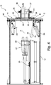
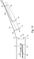
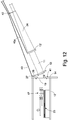
- the guiding rope 40 acts as a guide for the first case 11 until, as shown in figures 11 and 12 , it reaches a position close the second case 12 and the guide handle 26 engages with the seat 27 without intervention of any remotely operated vehicle.
- the first case 11 pivots around the seat 27, as from figure 12 , until the two first and second cases 11, 12 are aligned along the connecting axis A and the two first and second coupling ends 13, 14 are in reciprocal contact, with the help of conical centering studs 33 and stud seat 34.
- the locking clip 41 engages the lower rim of the first flange 25 securing the adherence of the first case 11 to the second case 12, before the fixing by bolts 30.
- first and second cases 11, 12 are fixed to each other to realize a watertight connection.
- the first and second cases 11, 12 are not permitted to move reciprocally.
- Such operation can be made by a remotely operated underwater vehicle (ROV) bearing a suitably arranged robot, or by an operator when the laying depth so permits.
- ROV underwater vehicle
- the securing fittings 21, associated with the second gate 19 are remotely operated, for example by a low voltage power feed line brought by the ROV, for opening the second gate 19 that rotates inward within the second case 12.
- the small volume of water remained entrapped between first and second gates 18, 19 during the fixing of the first and second cases 11, 12 flows down on the second gate 19 and/or the floor of the case 12, leaving the connecting interface substantially dry.
- the pushing actuator 22 acts on the securing fittings 20 of the first gate 18 which pivots inside the second case 12.
- the bearing structure 23 is remotely operated to move the second phase connectors 17 towards and after the connecting interface until engagement with the relevant first phase connectors 16.
- the length of cable 2 housed with the second case 12 allows such movement.
- the various actuators of the second case 12 are preferably hydraulic actuators, powered by a hydraulic unit (not shown), powered by a low voltage (e.g. 220V) power supply, independently brought to the second case 12 for mating or unmating operation.
- a hydraulic unit not shown
- a low voltage e.g. 220V
- the closing of the first and the second gates 18, 19 is performed by the remotely operated lifting actuator 39 pushing up the second gates 19 that, in turn, pushes up the first gate 18.
- the two first and second gates 18, 19 get at reach of the respective securing fittings 20, 21 that suitably fasten them, restoring the independent water tightness of the first and second cases 11 and 12, which can then be detached after removal of the bolts 30 by a ROV or by an operator.
- the wet mateable connection assembly as described allows a dry connection also in an undersea condition, with no need of insulating fluid.
- the wet mateable connection assembly according the present invention is simple, economical and functional.
- the materials used, as well as their dimensions, may be of suitable type depending on the technical requirements of the specific installation.
Landscapes
- Physics & Mathematics (AREA)
- General Physics & Mathematics (AREA)
- Optics & Photonics (AREA)
- Engineering & Computer Science (AREA)
- Manufacturing & Machinery (AREA)
- Connector Housings Or Holding Contact Members (AREA)
- Cable Accessories (AREA)
- Mechanical Coupling Of Light Guides (AREA)
- Light Guides In General And Applications Therefor (AREA)
Claims (21)
- Unter Wasser zusammensetzbare Verbindungs-Baugruppe (10), die umfasst:wenigstens ein erstes (11) und ein zweites (12) wasserdichtes Gehäuse, die wasserdicht zusammengesetzt werden können, wobei das erste und das zweite Gehäuse (11, 12) jeweils einen ersten (18) und einen zweiten (19) Verschluss an einem jeweiligen ersten (13) und zweiten (14) Kopplungs-Ende haben,wenigstens einen ersten Phasen-Verbinder (16), der im Inneren des ersten Gehäuses (11) angeordnet ist;wenigstens einen zweiten Phasen-Verbinder (17), der im Inneren des zweiten Gehäuses (12) angeordnet ist;
wobeider erste Verschluss (18) in das zweite Gehäuse (12) hinein bewegt werden kann, wenn das erste und das zweite Kopplungs-Ende (13, 14) zusammengefügt sind. - Unter Wasser zusammensetzbare Verbindungs-Baugruppe (10) nach Anspruch 1, wobei der erste Phasen-Verbinder (16) dem ersten Kopplungs-Ende (13) zugewandt befestigt ist und der zweite Phasen-Verbinder (17) von einer entfernten Position, an der der zweite Phasen-Verbinder (17) von dem zweiten Kopplungs-Ende (14) beabstandet ist, an eine Verbindungsposition bewegt werden kann, an der sich der zweite Phasen-Verbinder (17) durch das zweite Kopplungs-Ende (14) hindurch erstreckt und bis zu dem ersten Phasen-Verbinder (16) reicht.
- Unter Wasser zusammensetzbare Verbindungs-Baugruppe (10) nach Anspruch 1, wobei das erste Kopplungs-Ende (13) mit dem ersten Verschluss (18) versehen ist, der um eine Schwenkachse (B) herum bewegt werden kann, die im Wesentlichen rechtwinklig zu einer Längs-Verbindungsachse (A) ist.
- Unter Wasser zusammensetzbare Verbindungs-Baugruppe (10) nach Anspruch 3, wobei sowohl das erste als auch das zweite Kopplungs-Ende (13, 14) jeweils mit dem ersten Verschluss (18) und dem zweiten Verschluss (19) versehen sind, die um eine Schwenkachse (B,C) herum bewegt werden können, die im Wesentlichen rechtwinklig zu der längs-Verbindungsachse (A) ist.
- Unter Wasser zusammensetzbare Verbindungs-Baugruppe (10) nach Anspruch 1, wobei der erste Verschluss (18) an einer axial außen liegenden Position in Bezug auf das erste Gehäuse (11) angeordnet ist.
- Unter Wasser zusammensetzbare Verbindungs-Baugruppe (10) nach Anspruch 4, wobei der zweite Verschluss (19) an einer axial innen liegenden Position in Bezug auf das zweite Gehäuse (12) angeordnet ist.
- Unter Wasser zusammensetzbare Verbindungs-Baugruppe (10) nach Anspruch 4, wobei der erste und der zweite Verschluss (18, 19) in der gleichen axialen Richtung im rechten Winkel zu der Verbindungsachse (A) geschwenkt werden können.
- Unter Wasser zusammensetzbare Verbindungs-Baugruppe (10) nach Anspruch 1, wobei das erste und das zweite Gehäuse (11, 12) jeweils eine erste und eine zweite sichernde Armatur (20, 21) umfassen, mit denen die Verschlüsse (18, 19) wasserdicht verschlossen gehalten werden, und die betätigt werden können, um die Verschlüsse (18, 19) zu öffnen.
- Unter Wasser zusammensetzbare Verbindungs-Baugruppe (10) nach Anspruch 1, wobei sie ein Drück-Betätigungselement (22) umfasst, das im Inneren des zweiten Gehäuses (12) angeordnet ist.
- Unter Wasser zusammensetzbare Verbindungs-Baugruppe (10) nach Anspruch 1, wobei der zweite Phasen-Verbinder (17) an einer tragenden Struktur (23) im Inneren des zweiten Gehäuses (12) angebracht ist.
- Unter Wasser zusammensetzbare Verbindungs-Baugruppe (10) nach Anspruch 1, wobei der erste und der zweite Phasen-Verbinder (16, 17) jeweils mechanisch und elektrisch mit einem elektrischen oder optischen Kabel oder einem Hybrid-Kabel verbunden sind.
- Unter Wasser zusammensetzbare Verbindungs-Baugruppe (10) nach Anspruch 1, wobei der erste Phasen-Verbinder (16) in ein aushärtbares Material eingebettet ist.
- Unter Wasser zusammensetzbare Verbindungs-Baugruppe (10) nach Anspruch 1, wobei sie eine Biegeversteifung (24) umfasst, die an einem ersten gegenüberliegenden Ende (13') des ersten Gehäuses (11) befestigt ist.
- Unter Wasser zusammensetzbare Verbindungs-Baugruppe (10) nach Anspruch 1, wobei das erste Kopplungs-Ende (13) des ersten Gehäuses (11) einen Führungsgriff (26) umfasst, der im Wesentlichen senkrecht in Bezug auf die Verbindungsachse (12) vorsteht.
- Unter Wasser zusammensetzbare Verbindungs-Baugruppe (10) nach Anspruch 14, wobei der Führungsgriff (26) eine Form hat, die sich dazu eignet, das erste Gehäuse (11) an einem Führungsseil (40) aufgehängt zu führen.
- Unter Wasser zusammensetzbare Verbindungs-Baugruppe (10) nach Anspruch 1, wobei das zweite Kopplungs-Ende (14) eine Aufnahme (27) umfasst.
- Unter Wasser zusammensetzbare Verbindungs-Baugruppe (10) nach Anspruch 1, wobei das zweite Kopplungs-Ende (14) einen zweiten Flansch (35) mit wenigstens zwei Zentrierzapfen (33) umfasst und das erste Kopplungs-Ende (13) einen ersten Flansch (25) mit wenigstens zwei Zapfen-Aufnahmen (34) umfasst.
- Unter Wasser zusammensetzbare Verbindungs-Baugruppe (10) nach Anspruch 1, wobei sie eine Vielzahl von Dichtungsringen (28, 29) zwischen dem ersten und dem zweiten Kopplungs-Ende (13, 14) und dem ersten und dem zweiten Verschluss (18, 19) umfasst.
- Unter Wasser zusammensetzbare Verbindungs-Baugruppe (10) nach Anspruch 1, wobei das erste und das zweite Gehäuse (11, 12) mit Schrauben (30) aneinander befestigt sind.
- Unter Wasser zusammensetzbare Verbindungs-Baugruppe (10) nach Anspruch 1, wobei das zweite Kopplungs-Ende (14) eine Arretierklemme (41) umfasst.
- Verfahren zum Verbinden zweier Kabelenden unter Wasser, wobei das Verfahren die folgenden Schritte umfasst:Bereitstellen wenigstens eines ersten Phasen-Verbinders (16) in einem ersten wasserdichten Gehäuse (11), das einen ersten Verschluss (18) an einem ersten Kopplungs-Ende (13) enthält;Bereitstellen wenigstens eines zweiten Phasen-Verbinders (17) in einem zweiten wasserdichten Gehäuse (12), das einen zweiten Verschluss (19) an einem zweiten Kopplungs-Ende (14) enthält;wasserdichtes Befestigen des zweiten Gehäuses (12) an dem ersten Gehäuse (11) jeweils über das erste und das zweite Kopplungs-Ende (13, 14);Öffnen des zweiten Verschlusses (19), anschließend des ersten Verschlusses (18), wobei der erste Verschluss (18) geöffnet wird, indem er in das zweite Gehäuse (12) hinein bewegt wird; undaxiales Bewegen des zweiten Phasen-Verbinders (17), so dass er mit dem ersten Phasen-Verbinder (16) in Eingriff gebracht und funktional damit gekoppelt wird.
Applications Claiming Priority (1)
| Application Number | Priority Date | Filing Date | Title |
|---|---|---|---|
| PCT/IB2013/051227 WO2014125333A1 (en) | 2013-02-15 | 2013-02-15 | Wet mateable connection assembly for electrical and/or optical cables |
Publications (2)
| Publication Number | Publication Date |
|---|---|
| EP2957005A1 EP2957005A1 (de) | 2015-12-23 |
| EP2957005B1 true EP2957005B1 (de) | 2017-10-25 |
Family
ID=48048087
Family Applications (1)
| Application Number | Title | Priority Date | Filing Date |
|---|---|---|---|
| EP13714343.4A Active EP2957005B1 (de) | 2013-02-15 | 2013-02-15 | Nass zusammenpassbare verbindungseinheit für elektrische und/oder optische kabel |
Country Status (11)
| Country | Link |
|---|---|
| US (1) | US9477060B2 (de) |
| EP (1) | EP2957005B1 (de) |
| CN (1) | CN104995807B (de) |
| AR (1) | AR094795A1 (de) |
| AU (1) | AU2013378527B2 (de) |
| BR (1) | BR112015019225B1 (de) |
| CA (1) | CA2901067C (de) |
| DK (1) | DK2957005T3 (de) |
| NO (1) | NO2957005T3 (de) |
| NZ (1) | NZ711018A (de) |
| WO (1) | WO2014125333A1 (de) |
Families Citing this family (16)
| Publication number | Priority date | Publication date | Assignee | Title |
|---|---|---|---|---|
| NO2957006T3 (de) | 2013-02-15 | 2018-03-17 | ||
| WO2014155150A1 (en) * | 2013-03-26 | 2014-10-02 | Prysmian S.P.A. | Automated tightener for a wet mateable connection assembly |
| US9420503B2 (en) * | 2014-01-21 | 2016-08-16 | Cisco Technology, Inc. | System and method for seamless mobility in a network environment |
| CN105634621B (zh) * | 2016-03-16 | 2017-11-07 | 上海同济资产经营有限公司 | 海缆终端光电分离转换器 |
| US10063021B1 (en) * | 2017-04-28 | 2018-08-28 | Leviton Manufacturing Co., Inc. | Connector assembly with ball joint interface |
| CN107024743A (zh) * | 2017-06-13 | 2017-08-08 | 苏州专创光电科技有限公司 | 一种光纤连接器用保护箱 |
| GB2566980A (en) * | 2017-09-29 | 2019-04-03 | Siemens Ag | Coupling member for electrical connection |
| US10868384B1 (en) * | 2019-06-07 | 2020-12-15 | Northrop Grumman Systems Corporation | Self-insulating contacts for use in electrolytic environments |
| US12230910B2 (en) * | 2019-12-02 | 2025-02-18 | Siemens Energy AS | Single phase coupler |
| US12230914B2 (en) | 2020-02-25 | 2025-02-18 | In-Situ, Inc. | Universal load bearing cable connector |
| DE102020114197B3 (de) * | 2020-05-27 | 2021-08-05 | REVONEER GmbH | Schutzgehäuse für elektrische Stecker |
| CN111641074B (zh) * | 2020-07-06 | 2024-06-18 | 三亚氚海科技有限责任公司 | 一种湿插拔水密连接器 |
| JP7590217B2 (ja) * | 2021-03-01 | 2024-11-26 | 矢崎総業株式会社 | コネクタ |
| EP4113768A1 (de) * | 2021-07-02 | 2023-01-04 | Nexans | Trockenkupplungsabzweigklemme mit nassdesign und verfahren zur realisierung einer unterwasserverteilung von elektrischem strom für nasskabel |
| CN114811182B (zh) * | 2022-04-20 | 2024-05-31 | 北京京水建设集团有限公司 | 一种顶管段洞穿钢管施工结构及其施工方法 |
| WO2025219355A1 (en) * | 2024-04-19 | 2025-10-23 | Single Buoy Moorings Inc. | Subsea high voltage connector device |
Family Cites Families (22)
| Publication number | Priority date | Publication date | Assignee | Title |
|---|---|---|---|---|
| US4203640A (en) | 1979-01-24 | 1980-05-20 | The United States Of America As Represented By The Secretary Of The Interior | Electrical cable coupler with rotatable protective covers |
| US4874326A (en) * | 1988-09-20 | 1989-10-17 | The United States Of America As Represented By The Secretary Of The Navy | Elastomeric electrical isolation membrane |
| US4909751A (en) * | 1988-09-20 | 1990-03-20 | The United States Of America As Represented By The Secretary Of The Navy | Underwater mateable electrical connector |
| US4969924A (en) * | 1989-05-18 | 1990-11-13 | General Motors Corporation | Electro-optical connector plug |
| US5470248A (en) * | 1994-04-11 | 1995-11-28 | Tescorp Seismic Products, Inc. | Field repairable electrical connector |
| US5704799A (en) * | 1994-04-11 | 1998-01-06 | Tescorp Seismic Products, Inc. | Field repairable electrical connector |
| US5645438A (en) | 1995-01-20 | 1997-07-08 | Ocean Design, Inc. | Underwater-mateable connector for high pressure application |
| US6017227A (en) * | 1996-03-07 | 2000-01-25 | Ocean Design, Inc. | Underwater connector |
| US5738535A (en) * | 1996-03-07 | 1998-04-14 | Ocean Design, Inc. | Underwater connector |
| US5873750A (en) * | 1997-05-15 | 1999-02-23 | Ocean Design, Inc. | Underwater connector assembly |
| US6736545B2 (en) * | 1999-10-14 | 2004-05-18 | Ocean Design, Inc. | Wet mateable connector |
| GB2361725B (en) * | 2000-04-27 | 2002-07-03 | Fmc Corp | Central circulation completion system |
| US6332787B1 (en) * | 2000-08-18 | 2001-12-25 | Ocean Design, Inc. | Wet-mateable electro-optical connector |
| JP4550268B2 (ja) * | 2000-12-20 | 2010-09-22 | 古河電気工業株式会社 | 光・電気複合コネクタ |
| US6543965B2 (en) * | 2001-08-30 | 2003-04-08 | Ocean Design, Inc. | Underwater cable branching apparatus and method |
| US6402539B1 (en) * | 2001-10-16 | 2002-06-11 | Ocean Design, Inc. | Self-contained underwater cable branching apparatus and method |
| NO328726B1 (no) * | 2008-08-14 | 2010-05-03 | Roxar Flow Measurement As | Konnektorhus |
| EP2499706B1 (de) * | 2009-11-11 | 2016-08-24 | Teledyne Instruments, Inc. | Schlüsselloser stecker für unwirtliche umgebungen |
| US8272790B2 (en) * | 2009-11-24 | 2012-09-25 | Amphenol Fiber Optics | Outdoor transceiver connector |
| US8464797B2 (en) * | 2010-04-30 | 2013-06-18 | Hydril Usa Manufacturing Llc | Subsea control module with removable section and method |
| US8479828B2 (en) * | 2010-05-13 | 2013-07-09 | Weatherford/Lamb, Inc. | Wellhead control line deployment |
| NO2957006T3 (de) | 2013-02-15 | 2018-03-17 |
-
2013
- 2013-02-15 CA CA2901067A patent/CA2901067C/en active Active
- 2013-02-15 AU AU2013378527A patent/AU2013378527B2/en active Active
- 2013-02-15 NZ NZ711018A patent/NZ711018A/en unknown
- 2013-02-15 WO PCT/IB2013/051227 patent/WO2014125333A1/en not_active Ceased
- 2013-02-15 US US14/767,809 patent/US9477060B2/en active Active
- 2013-02-15 NO NO13714343A patent/NO2957005T3/no unknown
- 2013-02-15 BR BR112015019225-4A patent/BR112015019225B1/pt active IP Right Grant
- 2013-02-15 EP EP13714343.4A patent/EP2957005B1/de active Active
- 2013-02-15 CN CN201380072985.2A patent/CN104995807B/zh active Active
- 2013-02-15 DK DK13714343.4T patent/DK2957005T3/en active
-
2014
- 2014-02-14 AR ARP140100475A patent/AR094795A1/es active IP Right Grant
Non-Patent Citations (1)
| Title |
|---|
| None * |
Also Published As
| Publication number | Publication date |
|---|---|
| BR112015019225A2 (pt) | 2017-07-18 |
| CN104995807A (zh) | 2015-10-21 |
| AU2013378527A1 (en) | 2015-09-03 |
| US20150378125A1 (en) | 2015-12-31 |
| DK2957005T3 (en) | 2018-01-22 |
| BR112015019225B1 (pt) | 2020-12-22 |
| AU2013378527B2 (en) | 2017-06-08 |
| US9477060B2 (en) | 2016-10-25 |
| CN104995807B (zh) | 2017-05-17 |
| AR094795A1 (es) | 2015-08-26 |
| EP2957005A1 (de) | 2015-12-23 |
| CA2901067C (en) | 2019-06-18 |
| CA2901067A1 (en) | 2014-08-21 |
| NO2957005T3 (de) | 2018-03-24 |
| NZ711018A (en) | 2017-03-31 |
| WO2014125333A1 (en) | 2014-08-21 |
Similar Documents
| Publication | Publication Date | Title |
|---|---|---|
| CA2901067C (en) | Wet mateable connection assembly for electrical and/or optical cables | |
| EP2957006B1 (de) | Verfahren zum installieren einer nass zusammenpassbaren verbindungseinheit für elektrische und/oder optische kabel | |
| EP2570585A1 (de) | Unterwassertransformator | |
| EP3030743A2 (de) | Verbinder für unterseegebrauch | |
| BR112013026471B1 (pt) | Conector elétrico submarino para conectar infraestrutura de sistemas de controle ou alimentação | |
| CA2076008A1 (en) | Releasable hydraulic and/or electric connection for subsea equipment | |
| JP2026513791A (ja) | 改良型アンビリカル終端モジュール | |
| EP2979339B1 (de) | Automatisierte festschraubeinrichtung für eine nassverbindbare kupplungseinheit | |
| US8814584B2 (en) | Wet-mateable electrical connector | |
| US9929563B2 (en) | Subsea cable engagement system | |
| CN105933067A (zh) | 一种基于海底信号传输的光电转换装置 | |
| EP4331062B1 (de) | Verbinderkoppler |
Legal Events
| Date | Code | Title | Description |
|---|---|---|---|
| PUAI | Public reference made under article 153(3) epc to a published international application that has entered the european phase |
Free format text: ORIGINAL CODE: 0009012 |
|
| 17P | Request for examination filed |
Effective date: 20150724 |
|
| AK | Designated contracting states |
Kind code of ref document: A1 Designated state(s): AL AT BE BG CH CY CZ DE DK EE ES FI FR GB GR HR HU IE IS IT LI LT LU LV MC MK MT NL NO PL PT RO RS SE SI SK SM TR |
|
| AX | Request for extension of the european patent |
Extension state: BA ME |
|
| DAX | Request for extension of the european patent (deleted) | ||
| RAP1 | Party data changed (applicant data changed or rights of an application transferred) |
Owner name: PRYSMIAN S.P.A. |
|
| GRAP | Despatch of communication of intention to grant a patent |
Free format text: ORIGINAL CODE: EPIDOSNIGR1 |
|
| STAA | Information on the status of an ep patent application or granted ep patent |
Free format text: STATUS: GRANT OF PATENT IS INTENDED |
|
| INTG | Intention to grant announced |
Effective date: 20170512 |
|
| GRAS | Grant fee paid |
Free format text: ORIGINAL CODE: EPIDOSNIGR3 |
|
| GRAA | (expected) grant |
Free format text: ORIGINAL CODE: 0009210 |
|
| STAA | Information on the status of an ep patent application or granted ep patent |
Free format text: STATUS: THE PATENT HAS BEEN GRANTED |
|
| AK | Designated contracting states |
Kind code of ref document: B1 Designated state(s): AL AT BE BG CH CY CZ DE DK EE ES FI FR GB GR HR HU IE IS IT LI LT LU LV MC MK MT NL NO PL PT RO RS SE SI SK SM TR |
|
| REG | Reference to a national code |
Ref country code: GB Ref legal event code: FG4D |
|
| REG | Reference to a national code |
Ref country code: CH Ref legal event code: EP |
|
| REG | Reference to a national code |
Ref country code: AT Ref legal event code: REF Ref document number: 940737 Country of ref document: AT Kind code of ref document: T Effective date: 20171115 |
|
| REG | Reference to a national code |
Ref country code: IE Ref legal event code: FG4D |
|
| REG | Reference to a national code |
Ref country code: DE Ref legal event code: R096 Ref document number: 602013028367 Country of ref document: DE |
|
| REG | Reference to a national code |
Ref country code: DK Ref legal event code: T3 Effective date: 20180115 |
|
| REG | Reference to a national code |
Ref country code: NL Ref legal event code: FP |
|
| REG | Reference to a national code |
Ref country code: SE Ref legal event code: TRGR |
|
| REG | Reference to a national code |
Ref country code: FR Ref legal event code: PLFP Year of fee payment: 6 |
|
| REG | Reference to a national code |
Ref country code: LT Ref legal event code: MG4D |
|
| REG | Reference to a national code |
Ref country code: AT Ref legal event code: MK05 Ref document number: 940737 Country of ref document: AT Kind code of ref document: T Effective date: 20171025 |
|
| REG | Reference to a national code |
Ref country code: NO Ref legal event code: T2 Effective date: 20171025 |
|
| PG25 | Lapsed in a contracting state [announced via postgrant information from national office to epo] |
Ref country code: LT Free format text: LAPSE BECAUSE OF FAILURE TO SUBMIT A TRANSLATION OF THE DESCRIPTION OR TO PAY THE FEE WITHIN THE PRESCRIBED TIME-LIMIT Effective date: 20171025 Ref country code: FI Free format text: LAPSE BECAUSE OF FAILURE TO SUBMIT A TRANSLATION OF THE DESCRIPTION OR TO PAY THE FEE WITHIN THE PRESCRIBED TIME-LIMIT Effective date: 20171025 Ref country code: ES Free format text: LAPSE BECAUSE OF FAILURE TO SUBMIT A TRANSLATION OF THE DESCRIPTION OR TO PAY THE FEE WITHIN THE PRESCRIBED TIME-LIMIT Effective date: 20171025 |
|
| PG25 | Lapsed in a contracting state [announced via postgrant information from national office to epo] |
Ref country code: HR Free format text: LAPSE BECAUSE OF FAILURE TO SUBMIT A TRANSLATION OF THE DESCRIPTION OR TO PAY THE FEE WITHIN THE PRESCRIBED TIME-LIMIT Effective date: 20171025 Ref country code: BG Free format text: LAPSE BECAUSE OF FAILURE TO SUBMIT A TRANSLATION OF THE DESCRIPTION OR TO PAY THE FEE WITHIN THE PRESCRIBED TIME-LIMIT Effective date: 20180125 Ref country code: LV Free format text: LAPSE BECAUSE OF FAILURE TO SUBMIT A TRANSLATION OF THE DESCRIPTION OR TO PAY THE FEE WITHIN THE PRESCRIBED TIME-LIMIT Effective date: 20171025 Ref country code: GR Free format text: LAPSE BECAUSE OF FAILURE TO SUBMIT A TRANSLATION OF THE DESCRIPTION OR TO PAY THE FEE WITHIN THE PRESCRIBED TIME-LIMIT Effective date: 20180126 Ref country code: RS Free format text: LAPSE BECAUSE OF FAILURE TO SUBMIT A TRANSLATION OF THE DESCRIPTION OR TO PAY THE FEE WITHIN THE PRESCRIBED TIME-LIMIT Effective date: 20171025 Ref country code: IS Free format text: LAPSE BECAUSE OF FAILURE TO SUBMIT A TRANSLATION OF THE DESCRIPTION OR TO PAY THE FEE WITHIN THE PRESCRIBED TIME-LIMIT Effective date: 20180225 Ref country code: AT Free format text: LAPSE BECAUSE OF FAILURE TO SUBMIT A TRANSLATION OF THE DESCRIPTION OR TO PAY THE FEE WITHIN THE PRESCRIBED TIME-LIMIT Effective date: 20171025 |
|
| REG | Reference to a national code |
Ref country code: DE Ref legal event code: R097 Ref document number: 602013028367 Country of ref document: DE |
|
| PG25 | Lapsed in a contracting state [announced via postgrant information from national office to epo] |
Ref country code: SK Free format text: LAPSE BECAUSE OF FAILURE TO SUBMIT A TRANSLATION OF THE DESCRIPTION OR TO PAY THE FEE WITHIN THE PRESCRIBED TIME-LIMIT Effective date: 20171025 Ref country code: CY Free format text: LAPSE BECAUSE OF FAILURE TO SUBMIT A TRANSLATION OF THE DESCRIPTION OR TO PAY THE FEE WITHIN THE PRESCRIBED TIME-LIMIT Effective date: 20171025 Ref country code: EE Free format text: LAPSE BECAUSE OF FAILURE TO SUBMIT A TRANSLATION OF THE DESCRIPTION OR TO PAY THE FEE WITHIN THE PRESCRIBED TIME-LIMIT Effective date: 20171025 Ref country code: CZ Free format text: LAPSE BECAUSE OF FAILURE TO SUBMIT A TRANSLATION OF THE DESCRIPTION OR TO PAY THE FEE WITHIN THE PRESCRIBED TIME-LIMIT Effective date: 20171025 |
|
| PG25 | Lapsed in a contracting state [announced via postgrant information from national office to epo] |
Ref country code: RO Free format text: LAPSE BECAUSE OF FAILURE TO SUBMIT A TRANSLATION OF THE DESCRIPTION OR TO PAY THE FEE WITHIN THE PRESCRIBED TIME-LIMIT Effective date: 20171025 Ref country code: PL Free format text: LAPSE BECAUSE OF FAILURE TO SUBMIT A TRANSLATION OF THE DESCRIPTION OR TO PAY THE FEE WITHIN THE PRESCRIBED TIME-LIMIT Effective date: 20171025 Ref country code: SM Free format text: LAPSE BECAUSE OF FAILURE TO SUBMIT A TRANSLATION OF THE DESCRIPTION OR TO PAY THE FEE WITHIN THE PRESCRIBED TIME-LIMIT Effective date: 20171025 |
|
| PLBE | No opposition filed within time limit |
Free format text: ORIGINAL CODE: 0009261 |
|
| STAA | Information on the status of an ep patent application or granted ep patent |
Free format text: STATUS: NO OPPOSITION FILED WITHIN TIME LIMIT |
|
| REG | Reference to a national code |
Ref country code: CH Ref legal event code: PL |
|
| PG25 | Lapsed in a contracting state [announced via postgrant information from national office to epo] |
Ref country code: MC Free format text: LAPSE BECAUSE OF FAILURE TO SUBMIT A TRANSLATION OF THE DESCRIPTION OR TO PAY THE FEE WITHIN THE PRESCRIBED TIME-LIMIT Effective date: 20171025 |
|
| 26N | No opposition filed |
Effective date: 20180726 |
|
| REG | Reference to a national code |
Ref country code: IE Ref legal event code: MM4A |
|
| REG | Reference to a national code |
Ref country code: BE Ref legal event code: MM Effective date: 20180228 |
|
| PG25 | Lapsed in a contracting state [announced via postgrant information from national office to epo] |
Ref country code: CH Free format text: LAPSE BECAUSE OF NON-PAYMENT OF DUE FEES Effective date: 20180228 Ref country code: LI Free format text: LAPSE BECAUSE OF NON-PAYMENT OF DUE FEES Effective date: 20180228 Ref country code: LU Free format text: LAPSE BECAUSE OF NON-PAYMENT OF DUE FEES Effective date: 20180215 Ref country code: SI Free format text: LAPSE BECAUSE OF FAILURE TO SUBMIT A TRANSLATION OF THE DESCRIPTION OR TO PAY THE FEE WITHIN THE PRESCRIBED TIME-LIMIT Effective date: 20171025 |
|
| PG25 | Lapsed in a contracting state [announced via postgrant information from national office to epo] |
Ref country code: IE Free format text: LAPSE BECAUSE OF NON-PAYMENT OF DUE FEES Effective date: 20180215 |
|
| PG25 | Lapsed in a contracting state [announced via postgrant information from national office to epo] |
Ref country code: BE Free format text: LAPSE BECAUSE OF NON-PAYMENT OF DUE FEES Effective date: 20180228 |
|
| PG25 | Lapsed in a contracting state [announced via postgrant information from national office to epo] |
Ref country code: MT Free format text: LAPSE BECAUSE OF NON-PAYMENT OF DUE FEES Effective date: 20180215 |
|
| PG25 | Lapsed in a contracting state [announced via postgrant information from national office to epo] |
Ref country code: TR Free format text: LAPSE BECAUSE OF FAILURE TO SUBMIT A TRANSLATION OF THE DESCRIPTION OR TO PAY THE FEE WITHIN THE PRESCRIBED TIME-LIMIT Effective date: 20171025 |
|
| PG25 | Lapsed in a contracting state [announced via postgrant information from national office to epo] |
Ref country code: PT Free format text: LAPSE BECAUSE OF FAILURE TO SUBMIT A TRANSLATION OF THE DESCRIPTION OR TO PAY THE FEE WITHIN THE PRESCRIBED TIME-LIMIT Effective date: 20171025 |
|
| PG25 | Lapsed in a contracting state [announced via postgrant information from national office to epo] |
Ref country code: HU Free format text: LAPSE BECAUSE OF FAILURE TO SUBMIT A TRANSLATION OF THE DESCRIPTION OR TO PAY THE FEE WITHIN THE PRESCRIBED TIME-LIMIT; INVALID AB INITIO Effective date: 20130215 Ref country code: MK Free format text: LAPSE BECAUSE OF NON-PAYMENT OF DUE FEES Effective date: 20171025 |
|
| PG25 | Lapsed in a contracting state [announced via postgrant information from national office to epo] |
Ref country code: AL Free format text: LAPSE BECAUSE OF FAILURE TO SUBMIT A TRANSLATION OF THE DESCRIPTION OR TO PAY THE FEE WITHIN THE PRESCRIBED TIME-LIMIT Effective date: 20171025 |
|
| PGFP | Annual fee paid to national office [announced via postgrant information from national office to epo] |
Ref country code: NL Payment date: 20260226 Year of fee payment: 14 |
|
| PGFP | Annual fee paid to national office [announced via postgrant information from national office to epo] |
Ref country code: SE Payment date: 20260227 Year of fee payment: 14 |
|
| PGFP | Annual fee paid to national office [announced via postgrant information from national office to epo] |
Ref country code: GB Payment date: 20260227 Year of fee payment: 14 |
|
| PGFP | Annual fee paid to national office [announced via postgrant information from national office to epo] |
Ref country code: NO Payment date: 20260227 Year of fee payment: 14 Ref country code: DK Payment date: 20260225 Year of fee payment: 14 Ref country code: DE Payment date: 20260227 Year of fee payment: 14 |
|
| PGFP | Annual fee paid to national office [announced via postgrant information from national office to epo] |
Ref country code: IT Payment date: 20260219 Year of fee payment: 14 |
|
| PGFP | Annual fee paid to national office [announced via postgrant information from national office to epo] |
Ref country code: FR Payment date: 20260225 Year of fee payment: 14 |