EP2957012B1 - Verfahren für den betrieb einer windkraftanlage - Google Patents
Verfahren für den betrieb einer windkraftanlage Download PDFInfo
- Publication number
- EP2957012B1 EP2957012B1 EP13706162.8A EP13706162A EP2957012B1 EP 2957012 B1 EP2957012 B1 EP 2957012B1 EP 13706162 A EP13706162 A EP 13706162A EP 2957012 B1 EP2957012 B1 EP 2957012B1
- Authority
- EP
- European Patent Office
- Prior art keywords
- wind turbine
- grid
- short circuit
- fault
- plant
- Prior art date
- Legal status (The legal status is an assumption and is not a legal conclusion. Google has not performed a legal analysis and makes no representation as to the accuracy of the status listed.)
- Active
Links
Images


Classifications
-
- H—ELECTRICITY
- H02—GENERATION; CONVERSION OR DISTRIBUTION OF ELECTRIC POWER
- H02H—EMERGENCY PROTECTIVE CIRCUIT ARRANGEMENTS
- H02H3/00—Emergency protective circuit arrangements for automatic disconnection directly responsive to an undesired change from normal electric working condition with or without subsequent reconnection ; integrated protection
- H02H3/006—Calibration or setting of parameters
-
- F—MECHANICAL ENGINEERING; LIGHTING; HEATING; WEAPONS; BLASTING
- F03—MACHINES OR ENGINES FOR LIQUIDS; WIND, SPRING, OR WEIGHT MOTORS; PRODUCING MECHANICAL POWER OR A REACTIVE PROPULSIVE THRUST, NOT OTHERWISE PROVIDED FOR
- F03D—WIND MOTORS
- F03D7/00—Controlling wind motors
- F03D7/02—Controlling wind motors the wind motors having rotation axis substantially parallel to the air flow entering the rotor
- F03D7/0272—Controlling wind motors the wind motors having rotation axis substantially parallel to the air flow entering the rotor by measures acting on the electrical generator
-
- F—MECHANICAL ENGINEERING; LIGHTING; HEATING; WEAPONS; BLASTING
- F03—MACHINES OR ENGINES FOR LIQUIDS; WIND, SPRING, OR WEIGHT MOTORS; PRODUCING MECHANICAL POWER OR A REACTIVE PROPULSIVE THRUST, NOT OTHERWISE PROVIDED FOR
- F03D—WIND MOTORS
- F03D7/00—Controlling wind motors
- F03D7/02—Controlling wind motors the wind motors having rotation axis substantially parallel to the air flow entering the rotor
- F03D7/04—Automatic control; Regulation
- F03D7/042—Automatic control; Regulation by means of an electrical or electronic controller
- F03D7/048—Automatic control; Regulation by means of an electrical or electronic controller controlling wind farms
-
- F—MECHANICAL ENGINEERING; LIGHTING; HEATING; WEAPONS; BLASTING
- F03—MACHINES OR ENGINES FOR LIQUIDS; WIND, SPRING, OR WEIGHT MOTORS; PRODUCING MECHANICAL POWER OR A REACTIVE PROPULSIVE THRUST, NOT OTHERWISE PROVIDED FOR
- F03D—WIND MOTORS
- F03D9/00—Adaptations of wind motors for special use; Combinations of wind motors with apparatus driven thereby; Wind motors specially adapted for installation in particular locations
- F03D9/20—Wind motors characterised by the driven apparatus
- F03D9/25—Wind motors characterised by the driven apparatus the apparatus being an electrical generator
- F03D9/255—Wind motors characterised by the driven apparatus the apparatus being an electrical generator connected to electrical distribution networks; Arrangements therefor
- F03D9/257—Wind motors characterised by the driven apparatus the apparatus being an electrical generator connected to electrical distribution networks; Arrangements therefor the wind motor being part of a wind farm
-
- G—PHYSICS
- G05—CONTROLLING; REGULATING
- G05B—CONTROL OR REGULATING SYSTEMS IN GENERAL; FUNCTIONAL ELEMENTS OF SUCH SYSTEMS; MONITORING OR TESTING ARRANGEMENTS FOR SUCH SYSTEMS OR ELEMENTS
- G05B23/00—Testing or monitoring of control systems or parts thereof
- G05B23/02—Electric testing or monitoring
- G05B23/0205—Electric testing or monitoring by means of a monitoring system capable of detecting and responding to faults
- G05B23/0218—Electric testing or monitoring by means of a monitoring system capable of detecting and responding to faults characterised by the fault detection method dealing with either existing or incipient faults
- G05B23/0224—Process history based detection method, e.g. whereby history implies the availability of large amounts of data
- G05B23/0227—Qualitative history assessment, whereby the type of data acted upon, e.g. waveforms, images or patterns, is not relevant, e.g. rule based assessment; if-then decisions
- G05B23/0235—Qualitative history assessment, whereby the type of data acted upon, e.g. waveforms, images or patterns, is not relevant, e.g. rule based assessment; if-then decisions based on a comparison with predetermined threshold or range, e.g. "classical methods", carried out during normal operation; threshold adaptation or choice; when or how to compare with the threshold
-
- H—ELECTRICITY
- H01—ELECTRIC ELEMENTS
- H01H—ELECTRIC SWITCHES; RELAYS; SELECTORS; EMERGENCY PROTECTIVE DEVICES
- H01H71/00—Details of the protective switches or relays covered by groups H01H73/00 - H01H83/00
- H01H71/10—Operating or release mechanisms
-
- H—ELECTRICITY
- H01—ELECTRIC ELEMENTS
- H01H—ELECTRIC SWITCHES; RELAYS; SELECTORS; EMERGENCY PROTECTIVE DEVICES
- H01H81/00—Protective switches in which contacts are normally closed but are repeatedly opened and reclosed as long as a condition causing excess current persists, e.g. for current limiting
-
- H—ELECTRICITY
- H02—GENERATION; CONVERSION OR DISTRIBUTION OF ELECTRIC POWER
- H02H—EMERGENCY PROTECTIVE CIRCUIT ARRANGEMENTS
- H02H3/00—Emergency protective circuit arrangements for automatic disconnection directly responsive to an undesired change from normal electric working condition with or without subsequent reconnection ; integrated protection
- H02H3/02—Details
- H02H3/025—Disconnection after limiting, e.g. when limiting is not sufficient or for facilitating disconnection
-
- H—ELECTRICITY
- H02—GENERATION; CONVERSION OR DISTRIBUTION OF ELECTRIC POWER
- H02H—EMERGENCY PROTECTIVE CIRCUIT ARRANGEMENTS
- H02H3/00—Emergency protective circuit arrangements for automatic disconnection directly responsive to an undesired change from normal electric working condition with or without subsequent reconnection ; integrated protection
- H02H3/08—Emergency protective circuit arrangements for automatic disconnection directly responsive to an undesired change from normal electric working condition with or without subsequent reconnection ; integrated protection responsive to excess current
-
- H—ELECTRICITY
- H02—GENERATION; CONVERSION OR DISTRIBUTION OF ELECTRIC POWER
- H02H—EMERGENCY PROTECTIVE CIRCUIT ARRANGEMENTS
- H02H7/00—Emergency protective circuit arrangements specially adapted for specific types of electric machines or apparatus or for sectionalised protection of cable or line systems, and effecting automatic switching in the event of an undesired change from normal working conditions
- H02H7/08—Emergency protective circuit arrangements specially adapted for specific types of electric machines or apparatus or for sectionalised protection of cable or line systems, and effecting automatic switching in the event of an undesired change from normal working conditions for dynamo-electric motors
- H02H7/093—Emergency protective circuit arrangements specially adapted for specific types of electric machines or apparatus or for sectionalised protection of cable or line systems, and effecting automatic switching in the event of an undesired change from normal working conditions for dynamo-electric motors against increase beyond, or decrease below, a predetermined level of rotational speed
-
- H—ELECTRICITY
- H02—GENERATION; CONVERSION OR DISTRIBUTION OF ELECTRIC POWER
- H02J—ELECTRIC POWER NETWORKS; CIRCUIT ARRANGEMENTS OR SYSTEMS FOR SUPPLYING OR DISTRIBUTING ELECTRIC POWER; SYSTEMS FOR STORING ELECTRIC ENERGY
- H02J3/00—Circuit arrangements for AC mains or AC distribution networks
- H02J3/12—Arrangements for adjusting voltage in AC networks by changing a characteristic of the network load
- H02J3/16—Arrangements for adjusting voltage in AC networks by changing a characteristic of the network load by adjustment of reactive power
-
- H—ELECTRICITY
- H02—GENERATION; CONVERSION OR DISTRIBUTION OF ELECTRIC POWER
- H02J—ELECTRIC POWER NETWORKS; CIRCUIT ARRANGEMENTS OR SYSTEMS FOR SUPPLYING OR DISTRIBUTING ELECTRIC POWER; SYSTEMS FOR STORING ELECTRIC ENERGY
- H02J3/00—Circuit arrangements for AC mains or AC distribution networks
- H02J3/38—Arrangements for feeding a single network from two or more generators or sources in parallel; Arrangements for feeding already energised networks from additional generators or sources in parallel
- H02J3/381—Dispersed generators
-
- H—ELECTRICITY
- H02—GENERATION; CONVERSION OR DISTRIBUTION OF ELECTRIC POWER
- H02J—ELECTRIC POWER NETWORKS; CIRCUIT ARRANGEMENTS OR SYSTEMS FOR SUPPLYING OR DISTRIBUTING ELECTRIC POWER; SYSTEMS FOR STORING ELECTRIC ENERGY
- H02J3/00—Circuit arrangements for AC mains or AC distribution networks
- H02J3/38—Arrangements for feeding a single network from two or more generators or sources in parallel; Arrangements for feeding already energised networks from additional generators or sources in parallel
- H02J3/46—Controlling the sharing of generated power between the generators, sources or networks
- H02J3/50—Controlling the sharing of reactive power
-
- H—ELECTRICITY
- H02—GENERATION; CONVERSION OR DISTRIBUTION OF ELECTRIC POWER
- H02P—CONTROL OR REGULATION OF ELECTRIC MOTORS, ELECTRIC GENERATORS OR DYNAMO-ELECTRIC CONVERTERS; CONTROLLING TRANSFORMERS, REACTORS OR CHOKE COILS
- H02P9/00—Arrangements for controlling electric generators for the purpose of obtaining a desired output
- H02P9/006—Means for protecting the generator by using control
-
- H—ELECTRICITY
- H02—GENERATION; CONVERSION OR DISTRIBUTION OF ELECTRIC POWER
- H02H—EMERGENCY PROTECTIVE CIRCUIT ARRANGEMENTS
- H02H7/00—Emergency protective circuit arrangements specially adapted for specific types of electric machines or apparatus or for sectionalised protection of cable or line systems, and effecting automatic switching in the event of an undesired change from normal working conditions
- H02H7/26—Sectionalised protection of cable or line systems, e.g. for disconnecting a section on which a short-circuit, earth fault, or arc discharge has occured
- H02H7/30—Staggered disconnection
-
- H—ELECTRICITY
- H02—GENERATION; CONVERSION OR DISTRIBUTION OF ELECTRIC POWER
- H02J—ELECTRIC POWER NETWORKS; CIRCUIT ARRANGEMENTS OR SYSTEMS FOR SUPPLYING OR DISTRIBUTING ELECTRIC POWER; SYSTEMS FOR STORING ELECTRIC ENERGY
- H02J2101/00—Supply or distribution of decentralised, dispersed or local electric power generation
- H02J2101/20—Dispersed power generation using renewable energy sources
- H02J2101/28—Wind energy
-
- Y—GENERAL TAGGING OF NEW TECHNOLOGICAL DEVELOPMENTS; GENERAL TAGGING OF CROSS-SECTIONAL TECHNOLOGIES SPANNING OVER SEVERAL SECTIONS OF THE IPC; TECHNICAL SUBJECTS COVERED BY FORMER USPC CROSS-REFERENCE ART COLLECTIONS [XRACs] AND DIGESTS
- Y02—TECHNOLOGIES OR APPLICATIONS FOR MITIGATION OR ADAPTATION AGAINST CLIMATE CHANGE
- Y02E—REDUCTION OF GREENHOUSE GAS [GHG] EMISSIONS, RELATED TO ENERGY GENERATION, TRANSMISSION OR DISTRIBUTION
- Y02E10/00—Energy generation through renewable energy sources
- Y02E10/70—Wind energy
- Y02E10/72—Wind turbines with rotation axis in wind direction
-
- Y—GENERAL TAGGING OF NEW TECHNOLOGICAL DEVELOPMENTS; GENERAL TAGGING OF CROSS-SECTIONAL TECHNOLOGIES SPANNING OVER SEVERAL SECTIONS OF THE IPC; TECHNICAL SUBJECTS COVERED BY FORMER USPC CROSS-REFERENCE ART COLLECTIONS [XRACs] AND DIGESTS
- Y02—TECHNOLOGIES OR APPLICATIONS FOR MITIGATION OR ADAPTATION AGAINST CLIMATE CHANGE
- Y02E—REDUCTION OF GREENHOUSE GAS [GHG] EMISSIONS, RELATED TO ENERGY GENERATION, TRANSMISSION OR DISTRIBUTION
- Y02E10/00—Energy generation through renewable energy sources
- Y02E10/70—Wind energy
- Y02E10/76—Power conversion electric or electronic aspects
-
- Y—GENERAL TAGGING OF NEW TECHNOLOGICAL DEVELOPMENTS; GENERAL TAGGING OF CROSS-SECTIONAL TECHNOLOGIES SPANNING OVER SEVERAL SECTIONS OF THE IPC; TECHNICAL SUBJECTS COVERED BY FORMER USPC CROSS-REFERENCE ART COLLECTIONS [XRACs] AND DIGESTS
- Y02—TECHNOLOGIES OR APPLICATIONS FOR MITIGATION OR ADAPTATION AGAINST CLIMATE CHANGE
- Y02E—REDUCTION OF GREENHOUSE GAS [GHG] EMISSIONS, RELATED TO ENERGY GENERATION, TRANSMISSION OR DISTRIBUTION
- Y02E40/00—Technologies for an efficient electrical power generation, transmission or distribution
- Y02E40/30—Reactive power compensation
Definitions
- the present invention generally relates to a method of operating a wind turbine plant, in particular operating a wind turbine plant during a low voltage fault situation, in particular a short circuit fault.
- a wind turbine which is a rotating machine that converts the kinetic energy of the wind into mechanical energy, and the mechanical energy subsequently into electrical power.
- Common horizontal-axis wind turbines include a tower, a nacelle located at the apex of the tower, and a rotor that is supported in the nacelle by means of a shaft.
- the shaft couples the rotor either directly or indirectly with a rotor assembly of a generator housed inside the nacelle.
- a plurality of wind turbines may be arranged together to form a wind park or wind power plant.
- Wind power plants are coupled to an electrical network or grid which distributes electrical power by means of circuit breakers.
- infrastructure is generally inadequately set up to support the wind power plant electrical distribution.
- electrical grids which are far from the main generation units experience a phenomena known as "weak grid”.
- the present invention seeks to provide a solution to address the above situation.
- a method of operating a wind turbine plant comprising at least one transmission branch comprising a plurality of wind turbine generators, the transmission branch coupled to an electrical grid at a point of common coupling through at least one circuit breaker comprising a breaking capacity, the method comprising monitoring the electrical grid for a low voltage fault event; and if a low voltage fault event is detected: calculating a grid short circuit strength, determining a short circuit current limit if the grid short circuit strength requires an initial fault current contribution which exceeds the breaking capacity of the circuit breaker to be passed through the circuit breaker, determining a maximum fault current contribution based on the short circuit current limit and operating the wind turbine generators to provide to the electrical grid the maximum fault current contribution.
- the invention provides numerous advantages over the prior art.
- embodiments of the invention may achieve advantages over other possible solutions and/or over the prior art, whether or not a particular advantage is achieved by a given embodiment is not limiting of the invention.
- the following aspects, features, embodiments and advantages are merely illustrative and are not considered elements or limitations of the appended claims except where explicitly recited in a claim(s).
- reference to "the invention” shall not be construed as a generalization of any inventive subject matter disclosed herein and shall not be considered to be an element or limitation of the appended claims except where explicitly recited in a claim(s).
- a method of operating a wind turbine plant comprising at least one transmission branch comprising a plurality of wind turbine generators, the transmission branch coupled to an electrical grid at a point of common coupling through at least one circuit breaker comprising a breaking capacity, the method comprising monitoring the electrical grid for a low voltage fault event; and if a low voltage fault event is detected: calculating a grid short circuit strength, determining a short circuit current limit if the grid short circuit strength requires an initial fault current contribution which exceeds the breaking capacity of the circuit breaker to be passed through the circuit breaker, determining a maximum fault current contribution based on the short circuit current limit and operating the wind turbine generators to provide to the electrical grid the maximum fault current contribution.
- the typical requirement placed on wind turbine plants by grid codes incorporated by geographical transmission operators is the wind turbines to stay connected to the transmission grid and to provide as much reactive current as possible during low voltage fault events.
- the provision of the reactive current is required in supporting the transmission grid in recovering the grid voltage to its nominal value. Briefly, the more reactive current that is provided to the grid, the quicker it takes for the grid voltage to recover.
- Previous wind turbine plant systems have acceded to such grid requirements by setting their low voltage fault response to provide as much reactive current as the generating systems are able to.
- circuit breakers like other physical hardware switches are designed with a buffer to their operational capacity in order to accommodate most voltage fluctuations.
- the present assignees have discovered situations where typical operational design does not suitably cover the extreme fault situations. Instead of replacements of installed solutions, or putting in circuit breakers with higher capacity ratings in designing new plants, which are both costly and impractical, a solution based on the control of operational output of the wind turbine plant is proposed. Such a solution is cost-effective and eliminates the need of costly hardware solutions, while at the same time, only minimally reduces the rate at which the transmission grid might recover from the low voltage fault event.
- the grid short circuit strength is calculated, and a consideration made if the fault current contribution based on the grid short circuit strength requires an abnormally high reactive current support. A better understanding of the grid support requirement is made in taking into account the grid strength. This in turn leads to a more accurate modification of any changes to the power supplied to the grid.
- the method further comprises determining a corresponding maximum fault current contribution for each wind turbine generator, based on the short circuit current limit and an output capability of each wind turbine generator. In doing so, there is provided a finer control with regard to the fault injection support of the plant. This allows the different turbines in the plant to be optimized for fault support and the plant to provide as much fault injection support without compromising the health of the installed equipment.
- calculating a grid short circuit strength comprises injecting a predetermined amount of reactive power into the electrical grid at a defined location within the wind turbine plant, measuring a change in a voltage level of the grid, and determining a grid short circuit strength by comparing the change in the voltage level of the grid with the amount of injected reactive power.
- the short circuit current limit is determined to be the breaking capacity of the circuit breaker. This allows the plant power controller to modify the fault current injection while keeping track of the breaking capacity of the circuit breaker in concern. In situations where multiple circuit breakers are present in the wind turbine plant, and the grid short circuit strength requires an initial fault current contribution which exceeds the breaking capacity if more than one circuit breaker, the circuit breaker with the lowest breaking capacity will be taken in consideration for determining the short circuit current limit.
- determining the maximum fault current contribution comprises implementing the use of a weak grid injection profile in place of a conventional fault injection profile.
- the implementation of a weak grid injection profile allows the wind turbine converter controllers to immediately switch over to a maximum fault current contribution which is lower than what is required by a conventional fault injection profile.
- the weak grid fault injection profile is obtained by determining the maximum fault current contribution based on the grid short circuit strength, the present grid voltage and the breaking capacities of the circuit breakers in the plant, and lowering the reactive current injection gain in the injection profile, such that the output of the wind turbine plant matches the maximum fault current contribution.
- Pre-determining the maximum fault current injection, and implementing it onto a weak grid fault injection profile is advantageous in terms of computing and communication time saved in comparison to determining after the fault is detected.
- determining the maximum fault current contribution comprises iteratively lowering a power reference to be provided to the wind turbine generators such that the amount of fault current to be produced by the wind turbine generators drops below the short circuit current limit.
- Iteratively lowering the power reference allows the plant power controller to step through proper calculations to determine the maximum fault current contribution, and also allows the plant power controller to have a view on any further issues which might occur in running the plant with such a determined fault contribution.
- the low voltage fault event is any one of an electrical grid short circuit, an electrical grid fault, and a plant transmission circuit short circuit fault.
- Such events typically cause a drastic increase in the amount of current being transmitted due to the sharp drop in electrical resistance, and monitoring the plant allows the plant power controller to identify and react to these events.
- determining the corresponding maximum fault current contribution further comprises analyzing an operational status of the wind turbine generator. In a further embodiment, determining the corresponding maximum fault current contribution further comprises analyzing an operational status of a power converter in the wind turbine generator. Operational status such as the condition of the power converter, the number of parallel converter modules operational, the operating conditions of the generator windings and insulation, amongst others, are monitored and considered. This allows the plant power controller to optimally operate the individual wind turbines.
- a wind turbine plant comprising at least one transmission branch comprising a plurality of wind turbine generators, the transmission branch coupled to an electrical grid at a point of common coupling through at least one circuit breaker comprising a breaking capacity; and a wind turbine plant power control system comprising: a monitoring circuit configured to detect a low voltage fault event, a short circuit strength calculation unit configured to calculate a gird short circuit strength, a determination unit configured to determine a short circuit current limit if the grid short circuit strength requires an initial fault current contribution which exceeds the breaking capacity of the circuit breaker to be passed through the circuit breaker, a fault current determination unit configured to determine a maximum fault current contribution based on the short circuit current limit, and a power controller configured to send reference signals to the wind turbine generators to provide to the electrical grid the maximum fault current contribution.
- the determination unit is configured to determine a corresponding maximum fault current contribution for each wind turbine generator, based on the short circuit current limit and an output capability of each wind turbine generator.
- the fault current determination unit comprises a weak grid fault injection profile for use in place of a conventional fault injection profile.
- the plant further comprises a fault injection profile determination unit configured to determine the maximum fault current contribution based on the grid short circuit strength, the present grid voltage and the breaking capacities of the circuit breakers in the plant, and lowering the reactive current injection gain in the injection profile, such that the output of the wind turbine plant matches the maximum fault current contribution.
- the weak grid fault injection profile is provided to and stored in a wind turbine power converter control unit for operating the wind turbine generator.
- Fig. 1 illustrates a wind turbine plant layout according to an embodiment.
- wind turbine plant 100 comprises a plurality of transmission branches 110, 112, 114. each comprising a plurality of wind turbine generators 120 electrically connected to the transmission branch.
- the wind turbine plant 100 comprises a fleet of similar wind turbine generators 120.
- each wind turbine generator 120 is provided as a 3MW turbine.
- Each turbine 120 comprises a plurality of rotor blades driving a rotating main shaft which is mechanically coupled to a gearbox which steps up the rotation for a highspeed generator shaft.
- a permanent magnet generator is provided and mechanical torque is converted into electrical power, which is provided to a full-scale power converter for power conditioning.
- the output of the power converter is stepped up with a transformer provided in the turbine, which thereafter produces electrical power rated at 30kV to the transmission branches 110, 112, 114.
- the turbines in the plant comprise a generator which may be a singly or doubly-fed synchronous generator, an induction generator or any other type of generator comprising a stator winding.
- turbines in other embodiments may comprise direct drive or other alternative drive systems, which eliminate the use of a traditional gearbox.
- Each transmission branch 110, 112, 114 is coupled to a plant distribution line 124, which may also be known as a main bus bar, by a transmission branch circuit breaker 130, 132, 134.
- a plant distribution line 124 which may also be known as a main bus bar
- a transmission branch circuit breaker 130, 132, 134 is coupled to a plant distribution line 124, which may also be known as a main bus bar.
- a transmission branch circuit breaker 130, 132, 134 is coupled to a plant distribution line 124, which may also be known as a main bus bar.
- the function of the transmission branch circuit breaker is to protect both the wind turbines connected to the transmission branch and the other portions of the wind turbine plant from power surges or spikes which might take place when there is a fault in the grid or in the plant.
- the circuit breaker trips into an open circuit condition, and isolates the transmission branch from the wind turbine plant, until the fault is identified and addressed, and the electrical system is back in order for the reconnection of the transmission branch.
- circuit breakers 144 is rated at 25kA
- circuit breakers 130, 132 and 134 are rated at 20kA, which sufficiently caters to the requirement as according to the electrical layout of the wind turbine plant 100.
- Plant substations can either be a physical area of the wind turbine plant or an aggregated number of features spread over the plant.
- the substation 140 is presented as being located in one physical area.
- the main components of the substation are the main transformer 142, which steps up generated power in the plant to an appropriate voltage to be provided to an electrical grid 150, and the main switchgear 144, which defines an active switch for the wind turbine plant.
- the plant substation 140 sits in between the transmission branches 130, 132, 134 of the wind turbine plant 100 and the point of common coupling 146 to the electrical grid 150.
- some power compensation equipment 143 is located together with the plant substation 140.
- the power compensation equipment 143 in the present embodiment comprises STATCOMS, but other alternatives could also be possible, such as: switched capacitor banks, switched inductor banks, static condensers, and synchronous condensers.
- the power compensation equipment 143 is used to control the power factor, the level of reactive power contributed, or the voltage level of the point of common coupling ("PCC") 146. In other embodiments, the power compensation equipment could be distributed to each wind turbine generator 120.
- Operation of the wind turbine plant 100 is controlled by a plant power controller 148 that dispatches various reference set points to individual wind turbine generators 120 in the wind turbine plant 100.
- the plant power controller 148 also receives multiple sources of measurements from each wind turbine generator 120, as well as from various locations on the transmission branches 110, 112, 114, the distribution line 124, the plant substation 140, and the electrical grid 150, and uses the information received to optimize the wind turbine plant fault current contribution to the electrical grid.
- wind turbine plant 100 has been appended with an additional set of power generating sources 160.
- This scenario sometimes takes place when a plant developer decides that in maximizing the geographical land space, additional sources of power generation could be introduced, and with the wind turbine transmission layout probably being the only available electrical infrastructure, and sometimes piggybacks the additional sources onto it.
- the additional sources 160 are typically kept on a separate transmission line 162 with a dedicated step-up transformer 164 and isolation switch 166.
- the transmission line 162 couples onto the wind turbine plant network at the point of common coupling 146.
- the additional sources 160 can be switched over onto the plant distribution line 124 by opening the isolation switch 166 and closing a source switch 168.
- the plant substation 140 supports the stepping up of the power supplied by the additional sources 160 and the supply of the power to the electrical grid 150.
- additional sources 160 are gas turbines coupled to synchronous generators, but any other power generation sources, such as biodiesel, solar or hydroelectric, could be added.
- a fault is applied to the wind turbine plant layout of Fig. 1 .
- the additional sources 160 are connected to the wind turbine plant 100 and transmitting, together with the plurality of wind turbine generators 120, through the plant substation 140.
- the isolation switch 166 is open while source switch 168 is closed to facilitate the transfer of source onto the wind turbine plant transmission circuit.
- the fault occurring is an electrical grid 150 short circuit fault.
- the immediate response of the power plant controller 148 is to enter the wind turbine plant 100 into a low voltage ride through mode.
- wind turbine plants are often geographically isolated and may be connected to a weak grid. This is so in the present embodiment.
- weak grids large fault current contributions are required to maintain system stability. Theoretically, the larger the amount of reactive power contributed to the electrical system, the quicker the recovery, and the capacity of active power reception is improved.
- the required amount of fault contribution increases.
- the increase in reactive power contributed poses a risk of exceeding the breaking capacity of the existing circuit breakers in the plant.
- the grid short circuit strength, or short circuit ratio ("SCR") of the electrical grid 150 can be measured as the change in grid voltage level at the PCC 146 (dV) as a function of the change in output active power (dP) or reactive power (dQ) of the entire wind power plant.
- SCR short circuit strength, or short circuit ratio
- the identified fault current is a measure of what the electrical grid ideally requires the wind power plant 100 to provide.
- the plant power controller compares the identified fault current to the rated capacity of the circuit breakers 130, 132, 134 and the switchgear 144. If the required fault current exceeds the rated breaking capacity of any of the breakers, the plant power controller initiates a determination of a short circuit current limit which is established as the rated capacity of the affected breaker.
- a difference is then identified between the identified fault current and the short circuit current limit, and established as the amount of fault current to be reduced. It is assumed that the plant power controller 148 does not have control over the additional sources 160. As such, the only power generating sources that the controller 148 can affect are the wind turbine generators 120.
- the wind turbine generators provide a reactive power current linearly with respect to the per-unit power required. In requiring a reduction of the fault current contribution, the plant power controller 148 linearly scales down to obtain a reduced per-unit power reference to be provided to the wind turbine generators 120, such that the overall output of the wind turbine generators does not exceed the short circuit current limit.
- the output of the wind turbine generator 120, in response to the provided reduced power reference is referred to as the maximum fault current contribution.
- the present embodiment relates the invention as applied to a wind turbine plant 100 which is coupled with additional power sources 160. It is also applicable to standalone wind turbine plants. It is noted that situations where a wind power plant is coupled to a weak grid, large fault current contributions are required to maintain system stability during a low voltage event. If the low voltage event is caused by a short circuit within the wind power plant, for example a short on a transmission branch of the wind turbine plant which supports a plurality of wind turbines, by virtue of the drop in electrical impedance, all the current in the electrical circuit is drawn to the short circuit.
- the power producing sources such as the wind turbines, switch to a fault ride through mode and start producing as much reactive current as they are able to.
- the method according to the invention is able to handle such a scenario, by regulating a maximum fault current contribution from the power producing turbines, not only in the transmission branch at which the short circuit occurs, but on other transmission branches as well, as all current flows toward the short circuit during the fault.
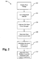
- Fig. 2 illustrates a flow chart diagram setting out a method of controlling a wind power plant 200 according to an embodiment.
- the voltage of the wind turbine plant is monitored for a low voltage event, particularly at the high voltage node of the substation, i.e. the point of common coupling with the electrical grid.
- a low voltage event is detected, which leads on to 206, at which a grid short circuit strength is calculated.
- a short circuit current limit is determined, if the grid short circuit strength requires a fault current contribution which exceeds the breaking capacity of the circuit breaker.
- a maximum fault current contribution based on the short circuit current limit is determined.
- the wind turbine generators of the wind power plant are operated to provide to the electrical grid the maximum fault current contribution.
- a wind turbine plant comprising a wind turbine plant power control system comprising: a monitoring circuit configured to detect a low voltage fault event, a short circuit strength calculation unit configured to calculate a gird short circuit strength, a determination unit configured to determine a short circuit current limit if the grid short circuit strength requires an initial fault current contribution which exceeds the breaking capacity of the circuit breaker to be passed through the circuit breaker, a fault current determination unit configured to determine a maximum fault current contribution based on the short circuit current limit, and a power controller configured to send reference signals to the wind turbine generators to provide to the electrical grid the maximum fault current contribution.
- a different fault injection profile is used to provide the maximum fault current contribution.
- the individual wind turbine controller immediately switches from normal production mode to a fault ride through mode, producing reactive current according to a predetermined current injection profile.
- Figure 3a illustrates a conventional reactive current injection profile 300 for low-voltage electrical faults. It may be noted that when the voltage drops to 0.8 p.u., the reactive current to be injected 302 has a gain of 10 and an output of 1.0 p.u.
- the grid short circuit strength is tracked, and in the event the grid short circuit strength requires a fault current contribution which exceeds the breaking capacity of the circuit breaker, the turbines switch to a weak grid fault injection profile with a determined lower gain, and thus lower output, applied to the reactive current injection.
- the maximum fault current contribution is thus limited by and set to the output of the weak grid fault injection profile.
- Fig 3b illustrates a weak grid injection profile 320 for low voltage electrical faults according to an embodiment.
- the weak grid fault injection profile and particularly the gain of the profile to determine the reactive current contribution 322, is determined iteratively. This determination is carried out on a regular basis, for example every 10 minutes (it can be less than 10 min up to 10 s, the frequency of calculation can be automated based on the previous samples rate of change of SCR at the PCC), and is based on the calculations of the grid short circuit strength, the present grid voltage, and the breaking capacities of the various circuit breakers in the plant. It may also include considering the output capabilities of the power sources in the wind turbine plant.
- the maximum fault current contribution is determined, and is applied to the weak grid injection profile by lowering the reactive current injection gain and output. This updated profile is then stored within the converter control system of each wind turbine, to be used with the method according to this embodiment.
- the wind turbine plant comprises multiple types of wind turbines in the plant, and a method of operating such a plant is provided, where a reduced per-unit power reference is determined for each individual turbine, based on the short circuit current limit, as well as the power producing capability of each turbine.
- the operational status of the wind turbine is considered in determining the reduced per-unit reactive current reference.
- Wind turbine power converters may in some instances comprise multiple lower-rated power converters stacked in a parallel configuration. If a lower-rated power converter is faulty, it may still be possible for the wind turbine power converter to function at a reduced rating.
- the operational status of each wind turbine power converter is considered in the determination of the corresponding maximum fault current contribution for each wind turbine generator.
- Other attributes of the wind turbine may also be considered, for example, the operational status of the electrical generator, in particular the generator windings and insulation as well as the electrical transformer.
Landscapes
- Engineering & Computer Science (AREA)
- Power Engineering (AREA)
- Life Sciences & Earth Sciences (AREA)
- Sustainable Development (AREA)
- Sustainable Energy (AREA)
- Chemical & Material Sciences (AREA)
- Combustion & Propulsion (AREA)
- Mechanical Engineering (AREA)
- General Engineering & Computer Science (AREA)
- Physics & Mathematics (AREA)
- General Physics & Mathematics (AREA)
- Automation & Control Theory (AREA)
- Control Of Eletrric Generators (AREA)
- Supply And Distribution Of Alternating Current (AREA)
Claims (15)
- Verfahren zum Betreiben eines Windparks (100), umfassend zumindest einen Übertragungszweig (110, 112, 114), der eine Vielzahl von Windkraftanlagen (120) umfasst, wobei der Übertragungszweig mit einem elektrischen Netz (150) an einem gemeinsamen Kopplungspunkt (146) über zumindest einen Leistungsschalter (130, 132, 134), der eine Ausschaltleistung umfasst, gekoppelt ist, dadurch gekennzeichnet, dass das Verfahren umfasst:Überwachen des Windparks für ein Niederspannungsfehlerereignis; und wenn ein Niederspannungsfehlerereignis erkannt wird:- Berechnen einer Netzkurzschlussstärke,- Bestimmen einer Kurzschlussstromgrenze, wenn die Netzkurzschlussstärke einen anfänglichen Fehlerstrombeitrag erfordert, der die Ausschaltleistung des Leistungsschalters, die den Leistungsschalter (130, 132, 134) durchlaufen soll, überschreitet,- Bestimmen eines maximalen Fehlerstrombeitrages basierend auf der Kurzschlussstromgrenze, und- Betreiben der Windkraftanlagen (120), um den maximalen Fehlerstrombeitrag für das elektrische Netz (150) bereitzustellen.
- Verfahren nach Anspruch 1, weiterhin umfassend:- Bestimmen eines entsprechenden maximalen Fehlerstrombeitrages für jede Windkraftanlage (120), basierend auf der Kurzschlussstromgrenze und einer Ausgangsfähigkeit jeder Windkraftanlage (120).
- Verfahren nach Anspruch 1, wobei das Berechnen einer Netzkurzschlussstärke umfasst:- Injizieren einer vorgegebenen Menge an Blindleistung in das elektrische Netz (150) an einer definierten Stelle innerhalb des Windparks (100),- Messen einer Änderung in einem Spannungsniveau des Netzes, und- Bestimmen einer Netzkurzschlussstärke durch Vergleichen der Änderung in dem Spannungsniveau des Netzes mit der Menge an injizierter Blindleistung.
- Verfahren nach einem der vorhergehenden Ansprüche, wobei die Kurzschlussstromgrenze bestimmt wird, um die Ausschaltleistung des Leistungsschalters (130, 132, 134) zu sein.
- Verfahren nach einem der vorhergehenden Ansprüche, wobei das Bestimmen des maximalen Fehlerstrombeitrages umfasst:- Implementieren der Verwendung eines Profils für schwache Netzfehlerinjektion anstelle eines Profils für gewöhnliche Netzfehlerinjektion.
- Verfahren nach Anspruch 5, wobei das Profil für schwache Netzfehlerinjektion erhalten wird durch:- Bestimmen des maximalen Fehlerstrombeitrages basierend auf der Netzkurzschlussstärke, der gegenwärtigen Netzspannung und der Ausschaltleistungen der Leistungsschalter in der Anlage, und- Verringern der Blindstrominjektionsverstärkung in dem Injektionsprofil, sodass der Ausgang des Windparks mit dem maximalen Fehlerstrombeitrag übereinstimmt.
- Verfahren nach Anspruch 1, wobei das Bestimmen des maximalen Fehlerstrombeitrages umfasst:- Verringern einer Leistungsreferenz, die für die Windkraftanlagen (120) bereitgestellt werden soll, sodass die Menge an Fehlerstrom, die von den Windkraftanlagen (120) erzeugt werden soll, unter die Kurzschlussstromgrenze fällt.
- Verfahren nach einem der vorhergehenden Ansprüche, wobei das Niederspannungsfehlerereignis eines von einem Kurzschluss des elektrischen Netzes, einem Fehler des elektrischen Netzes und einem Kurzschlussfehler der Anlagenübertragungsschaltung ist.
- Verfahren nach Anspruch 2, wobei das Bestimmen des entsprechenden maximalen Fehlerstrombeitrages weiterhin Analysieren eines Betriebszustandes der Windkraftanlage (120) umfasst.
- Verfahren nach Anspruch 9, wobei das Bestimmen des entsprechenden maximalen Fehlerstrombeitrages weiterhin Analysieren eines Betriebszustandes eines Leistungswandlers in der Windkraftanlage (120) umfasst.
- Windpark (100), umfassend zumindest einen Übertragungszweig (110, 112, 114), der eine Vielzahl von Windkraftanlagen (120) umfasst, wobei der Übertragungszweig mit einem elektrischen Netz (150) an einem gemeinsamen Kopplungspunkt (146) über zumindest einen Leistungsschalter (130, 132, 134), der eine Ausschaltleistung umfasst, gekoppelt ist;dadurch gekennzeichnet, dass der Windpark weiterhin umfasst ein Windpark-Steuersystem, umfassend:- eine Überwachungsschaltung, ausgebildet zum Erkennen eines Niederspannungsfehlerereignisses,- eine Kurzschlussstärkenberechnungseinheit, ausgebildet zum Berechnen einer Netzkurzschlussstärke,- eine Bestimmungseinheit, ausgebildet zum Bestimmen einer Kurzschlussstromgrenze, wenn die Netzkurzschlussstärke einen anfänglichen Fehlerstrombeitrag erfordert, der die Ausschaltleistung des Leistungsschalters, die den Leistungsschalter durchlaufen soll, überschreitet,- eine Fehlerstrombestimmungseinheit, ausgebildet zum Bestimmen eines maximalen Fehlerstrombeitrages basierend auf der Kurzschlussstromgrenze, und- Leistungssteuervorrichtung, ausgebildet zum Senden eines Referenzsignals zu den Windkraftanlagen, um den maximalen Fehlerstrombeitrag für das elektrische Netz bereitzustellen.
- Windpark (100) nach Anspruch 11, wobei die Bestimmungseinheit ausgebildet ist zum Bestimmen eines entsprechenden maximalen Fehlerstrombeitrages für jede Windkraftanlage (120), basierend auf der Kurzschlussstromgrenze und einer Ausgangsfähigkeit jeder Windkraftanlage (120).
- Windpark (100) nach Anspruch 11, wobei die Fehlerstrombestimmungseinheit ein Profil für schwache Netzfehlerinjektion umfasst, zur Verwendung anstelle eines Profils für gewöhnliche Netzfehlerinjektion.
- Windpark (100) nach Anspruch 13, weiterhin umfassend eine Fehlerinjektionsprofilbestimmungseinheit, ausgebildet zum Bestimmen des maximalen Fehlerstrombeitrages basierend auf der Netzkurzschlussstärke, der gegenwärtigen Netzspannung und der Ausschaltleistungen der Leistungsschalter in der Anlage, und zum Verringern der Blindstrominjektionsverstärkung in dem Injektionsprofil, sodass der Ausgang des Windparks mit dem maximalen Fehlerstrombeitrag übereinstimmt.
- Windpark (100) nach Ansprüchen 13 oder 14, wobei das Profil für schwache Netzfehlerinjektion bereitgestellt wird für und gespeichert wird in einer Windturbinen-Leistungswandler-Steuereinheit zum Betreiben der Windkraftanlage.
Applications Claiming Priority (1)
| Application Number | Priority Date | Filing Date | Title |
|---|---|---|---|
| PCT/DK2013/050039 WO2014124644A1 (en) | 2013-02-15 | 2013-02-15 | A method of operating a wind turbine plant |
Publications (2)
| Publication Number | Publication Date |
|---|---|
| EP2957012A1 EP2957012A1 (de) | 2015-12-23 |
| EP2957012B1 true EP2957012B1 (de) | 2017-05-03 |
Family
ID=47750377
Family Applications (1)
| Application Number | Title | Priority Date | Filing Date |
|---|---|---|---|
| EP13706162.8A Active EP2957012B1 (de) | 2013-02-15 | 2013-02-15 | Verfahren für den betrieb einer windkraftanlage |
Country Status (4)
| Country | Link |
|---|---|
| US (1) | US9556853B2 (de) |
| EP (1) | EP2957012B1 (de) |
| CN (1) | CN104995812B (de) |
| WO (1) | WO2014124644A1 (de) |
Families Citing this family (32)
| Publication number | Priority date | Publication date | Assignee | Title |
|---|---|---|---|---|
| KR101480533B1 (ko) * | 2013-06-28 | 2015-01-08 | 한국전력공사 | 분산전원 전력계통 연계 운전장치 및 방법 |
| EP3075055B1 (de) * | 2013-11-28 | 2019-03-06 | Vestas Wind Systems A/S | Kraftwerksteuerung zur erzeugung einer stromreferenz zu windturbinengeneratoren |
| US10042374B2 (en) * | 2014-06-13 | 2018-08-07 | Siemens Gamesa Renewable Energy A/S | Method and apparatus for determining a weakened grid condition and controlling a power plant in a manner appropriate to the grid condition |
| WO2016062316A1 (en) * | 2014-10-24 | 2016-04-28 | Vestas Wind Systems A/S | Method for operating a wind power plant in a weak grid environment and a wind power plant |
| CN104836503B (zh) * | 2015-05-14 | 2016-03-30 | 贵州电网有限责任公司电力调度控制中心 | 不对称故障下的双馈风力发电机定子短路电流计算方法 |
| US9866063B2 (en) * | 2016-04-05 | 2018-01-09 | Nuscale Power, Llc | Fault-tolerant power distribution systems for a modular power plant |
| US9970417B2 (en) * | 2016-04-14 | 2018-05-15 | General Electric Company | Wind converter control for weak grid |
| CN105932672B (zh) * | 2016-06-02 | 2022-02-22 | 中国电力科学研究院 | 一种电力系统短路工频电气量的计算方法 |
| US11619206B2 (en) * | 2016-06-21 | 2023-04-04 | General Electric Company | System and method for controlling a power generating unit |
| US10539118B2 (en) * | 2016-07-06 | 2020-01-21 | Vestas Wind Systmens A/S | Wind power plant having a plurality of wind turbine generators and a power plant controller |
| DE102016124840A1 (de) | 2016-12-19 | 2018-06-21 | Wobben Properties Gmbh | Verfahren zum Steuern eines Netzwiederaufbaus |
| US10305282B2 (en) * | 2017-04-20 | 2019-05-28 | Rockwell Automation Technologies, Inc. | Initiating a control function based on real time available fault current measurement |
| ES2688089A1 (es) * | 2017-04-28 | 2018-10-30 | Gamesa Innovation & Tecnology S.L. | Método de control para una planta eólica, y planta eólica asociada |
| US10428797B2 (en) * | 2017-07-05 | 2019-10-01 | Inventus Holdings, Llc | Wind farm power regulation |
| US10756658B2 (en) * | 2017-07-06 | 2020-08-25 | General Electric Company | Allocating reactive power production for doubly fed induction generator wind turbine system |
| FR3071620B1 (fr) * | 2017-09-26 | 2020-10-02 | Ge Energy Power Conversion Technology Ltd | Dispositif et procede de test de modules de puissance |
| US10651654B2 (en) * | 2017-11-07 | 2020-05-12 | State Grid Corporation Of China | Model predictive controller for autonomous hybrid microgrids |
| US10819103B2 (en) * | 2017-12-07 | 2020-10-27 | General Electric Company | Systems and methods for isolating faults in electrical power systems connected to a power grid |
| CN108051549B (zh) * | 2017-12-15 | 2024-03-15 | 中国科学院南京地理与湖泊研究所 | 一种测定水生植物能承受的水流临界流速的装置与方法 |
| US10644500B2 (en) * | 2018-01-02 | 2020-05-05 | Ge Global Sourcing Llc | Ceramic permanent magnet protection |
| US10978943B2 (en) | 2019-04-03 | 2021-04-13 | General Electric Company | System and method for auto-ramping and energy dump for a superconducting wind turbine generator |
| US11521771B2 (en) | 2019-04-03 | 2022-12-06 | General Electric Company | System for quench protection of superconducting machines, such as a superconducting wind turbine generator |
| US10985611B2 (en) * | 2019-04-10 | 2021-04-20 | General Electric Company | System and method for estimating grid strength |
| US10742149B1 (en) | 2019-04-22 | 2020-08-11 | General Electric Company | System and method for reactive power control of a wind turbine by varying switching frequency of rotor side converter |
| US10581247B1 (en) | 2019-05-06 | 2020-03-03 | General Electric Company | System and method for reactive power control of wind turbines in a wind farm supported with auxiliary reactive power compensation |
| US10790668B1 (en) | 2019-05-06 | 2020-09-29 | General Electric Company | Method for reactive power oscillation damping for a wind turbine system with integrated reactive power compensation device |
| US11056884B2 (en) | 2019-05-06 | 2021-07-06 | General Electric Company | Wind turbine system with integrated reactive power compensation device |
| US10731628B1 (en) | 2019-05-06 | 2020-08-04 | General Electric Company | System and method for coordinated control of reactive power from a generator and a reactive power compensation device in a wind turbine system |
| US11070061B2 (en) * | 2019-10-04 | 2021-07-20 | AES Gener S.A. | Virtual reservoir storing energy for a hydroelectric power plant |
| CN110912151B (zh) * | 2019-12-19 | 2021-04-13 | 西安西电电力电容器有限责任公司 | 用于交流输电线路的柱上无功补偿控制方法和装置 |
| CN115191069A (zh) * | 2020-02-26 | 2022-10-14 | 维斯塔斯风力系统集团公司 | 用于在电压事件期间控制可再生发电厂的方法 |
| AT524421B1 (de) * | 2020-11-30 | 2022-06-15 | Univ Graz Tech | Verfahren zur zeitstaffelungsschutzkompatiblen selektiven netzkurzschlusserkennenden Überwachung des Betriebes eines elektrischen Energienetzes |
Family Cites Families (14)
| Publication number | Priority date | Publication date | Assignee | Title |
|---|---|---|---|---|
| SE0303574D0 (sv) * | 2003-12-23 | 2003-12-23 | Abb Research Ltd | Elictric power network |
| DE102005031833B4 (de) * | 2005-07-06 | 2017-01-05 | Phoenix Contact Gmbh & Co. Kg | Verfahren und elektronische Stromversorgungsvorrichtung zur Energieversorgung einer durch eine Schutzeinrichtung gesicherten Niederspannungslast |
| US8131401B2 (en) * | 2006-07-19 | 2012-03-06 | Power Analytics Corporation | Real-time stability indexing for intelligent energy monitoring and management of electrical power network system |
| US8234015B2 (en) | 2007-12-28 | 2012-07-31 | Vestas Wind Systems A/S | Method for controlling a grid voltage |
| DE102009038209A1 (de) * | 2008-08-21 | 2010-02-25 | Moeller Gmbh | Begrenzungsvorrichtung für Fehlerströme in einer Wechselstrom-Niederspannungsanlage |
| EP2194656B1 (de) * | 2008-12-03 | 2014-06-25 | ABB Research Ltd. | System zur Datenverwaltung für elektrische Energieversorgungsnetze |
| CA2768101A1 (en) * | 2009-09-15 | 2011-03-24 | The University Of Western Ontario | Utilization of distributed generator inverters as statcom |
| US10063059B2 (en) * | 2009-10-27 | 2018-08-28 | Vestas Wind Systems A/S | Wind power plant with optimal power output |
| EP2463979B1 (de) * | 2010-12-08 | 2022-05-11 | Siemens Aktiengesellschaft | FRT-Verfahren, Wandler und Stromerzeugungsgerät für eine Windturbine |
| WO2012103246A2 (en) * | 2011-01-25 | 2012-08-02 | Power Analytics Corporation | Systems and methods for real-time dc microgrid power analytics for mission-critical power systems |
| EP2481915A1 (de) * | 2011-01-26 | 2012-08-01 | Chapdrive As | Verfahren und System zum Anschließen einer Windkraftanlage an ein Stromnetz |
| JP5627529B2 (ja) | 2011-04-01 | 2014-11-19 | 三菱重工業株式会社 | 風力発電装置の制御装置、風力発電装置、ウインドファーム、及び風力発電装置の制御方法 |
| EP2722861B8 (de) * | 2012-10-22 | 2016-09-21 | ABB Schweiz AG | Fehlerstrombegrenzeranordnung |
| US9755430B2 (en) * | 2013-04-11 | 2017-09-05 | Solantro Semiconductor Corp. | Virtual inverter for power generation units |
-
2013
- 2013-02-15 EP EP13706162.8A patent/EP2957012B1/de active Active
- 2013-02-15 US US14/765,938 patent/US9556853B2/en active Active
- 2013-02-15 CN CN201380073041.7A patent/CN104995812B/zh active Active
- 2013-02-15 WO PCT/DK2013/050039 patent/WO2014124644A1/en not_active Ceased
Also Published As
| Publication number | Publication date |
|---|---|
| CN104995812B (zh) | 2017-09-19 |
| US9556853B2 (en) | 2017-01-31 |
| CN104995812A (zh) | 2015-10-21 |
| WO2014124644A1 (en) | 2014-08-21 |
| US20150369217A1 (en) | 2015-12-24 |
| EP2957012A1 (de) | 2015-12-23 |
Similar Documents
| Publication | Publication Date | Title |
|---|---|---|
| US9556853B2 (en) | Method of operating a wind turbine plant | |
| Gu et al. | Review of system strength and inertia requirements for the national electricity market of Australia | |
| Xie et al. | A system-wide protection against unstable SSCI in series-compensated wind power systems | |
| Iov et al. | Mapping of grid faults and grid codes | |
| Bevrani et al. | Renewable energy sources and frequency regulation: survey and new perspectives | |
| Lin et al. | Adaptive distance protection for microgrids | |
| Altin et al. | Methodology for assessment of inertial response from wind power plants | |
| Feltes et al. | Wind turbine generator dynamic performance with weak transmission grids | |
| Fagan et al. | Grid code provisions for wind generators in Ireland | |
| Martin-Martinez et al. | Participation of wind power plants in the Spanish power system during events | |
| Bollen et al. | Overload and overvoltage in low-voltage and medium-voltage networks due to renewable energy—Some illustrative case studies | |
| Dalmau et al. | Decentralized voltage control coordination of on-load tap changer transformers, distributed generation units and flexible loads | |
| Wang et al. | Real‐time optimisation of short‐term frequency stability controls for a power system with renewables and multi‐infeed HVDCs | |
| Singh et al. | IBR performance issues: Potential threat to grid stability and security | |
| Authority et al. | Evaluating the impacts of wind farms on power system operation | |
| CN113497442A (zh) | 一种针对同杆并架线路的交流输电断面传输极限计算方法 | |
| Cheah | Offshore wind integration through high voltage direct current systems | |
| Qureshi et al. | Systematic development of Low Voltage Ride-Through (LVRT) envelope for grids | |
| CN114825360A (zh) | 用于控制风能设备或风电场的方法、风能设备和风电场 | |
| Joian et al. | The Experimental Determinations at the Wind Farm Fantanele–Cogealac in Dobrogea | |
| KR102954757B1 (ko) | 주파수 안정도 평가 시스템 및 방법 | |
| CN114678847B (zh) | 考虑海缆寿命的海上风电场中性点接地方式决策方法 | |
| CN118920439B (zh) | 考虑馈线负载率的海上风电系统可靠性评估方法和设备 | |
| Dai et al. | Differences in stability studies of power systems under the presence of a high penetration of renewable energy sources in Portugal and China | |
| Zhao et al. | Influence of DFIG models on fault current calculation and protection coordination |
Legal Events
| Date | Code | Title | Description |
|---|---|---|---|
| PUAI | Public reference made under article 153(3) epc to a published international application that has entered the european phase |
Free format text: ORIGINAL CODE: 0009012 |
|
| 17P | Request for examination filed |
Effective date: 20150908 |
|
| AK | Designated contracting states |
Kind code of ref document: A1 Designated state(s): AL AT BE BG CH CY CZ DE DK EE ES FI FR GB GR HR HU IE IS IT LI LT LU LV MC MK MT NL NO PL PT RO RS SE SI SK SM TR |
|
| AX | Request for extension of the european patent |
Extension state: BA ME |
|
| DAX | Request for extension of the european patent (deleted) | ||
| 17Q | First examination report despatched |
Effective date: 20160617 |
|
| RIC1 | Information provided on ipc code assigned before grant |
Ipc: H02J 3/38 20060101ALI20161102BHEP Ipc: H02H 3/00 20060101ALI20161102BHEP Ipc: H02J 3/16 20060101AFI20161102BHEP Ipc: H02H 7/30 20060101ALI20161102BHEP |
|
| GRAP | Despatch of communication of intention to grant a patent |
Free format text: ORIGINAL CODE: EPIDOSNIGR1 |
|
| INTG | Intention to grant announced |
Effective date: 20170110 |
|
| RIN1 | Information on inventor provided before grant (corrected) |
Inventor name: GUPTA, AMIT, KUMAR Inventor name: GURU, DILIP, KUMAR Inventor name: GUPTA, MANOJ |
|
| GRAS | Grant fee paid |
Free format text: ORIGINAL CODE: EPIDOSNIGR3 |
|
| GRAA | (expected) grant |
Free format text: ORIGINAL CODE: 0009210 |
|
| AK | Designated contracting states |
Kind code of ref document: B1 Designated state(s): AL AT BE BG CH CY CZ DE DK EE ES FI FR GB GR HR HU IE IS IT LI LT LU LV MC MK MT NL NO PL PT RO RS SE SI SK SM TR |
|
| REG | Reference to a national code |
Ref country code: GB Ref legal event code: FG4D |
|
| RIN1 | Information on inventor provided before grant (corrected) |
Inventor name: GUPTA, AMIT, KUMAR Inventor name: GUPTA, MANOJ Inventor name: GURU, DILIP, KUMAR |
|
| REG | Reference to a national code |
Ref country code: AT Ref legal event code: REF Ref document number: 890976 Country of ref document: AT Kind code of ref document: T Effective date: 20170515 Ref country code: CH Ref legal event code: EP |
|
| REG | Reference to a national code |
Ref country code: IE Ref legal event code: FG4D |
|
| REG | Reference to a national code |
Ref country code: DE Ref legal event code: R096 Ref document number: 602013020563 Country of ref document: DE |
|
| REG | Reference to a national code |
Ref country code: NL Ref legal event code: MP Effective date: 20170503 |
|
| REG | Reference to a national code |
Ref country code: AT Ref legal event code: MK05 Ref document number: 890976 Country of ref document: AT Kind code of ref document: T Effective date: 20170503 |
|
| REG | Reference to a national code |
Ref country code: LT Ref legal event code: MG4D |
|
| PG25 | Lapsed in a contracting state [announced via postgrant information from national office to epo] |
Ref country code: LT Free format text: LAPSE BECAUSE OF FAILURE TO SUBMIT A TRANSLATION OF THE DESCRIPTION OR TO PAY THE FEE WITHIN THE PRESCRIBED TIME-LIMIT Effective date: 20170503 Ref country code: AT Free format text: LAPSE BECAUSE OF FAILURE TO SUBMIT A TRANSLATION OF THE DESCRIPTION OR TO PAY THE FEE WITHIN THE PRESCRIBED TIME-LIMIT Effective date: 20170503 Ref country code: FI Free format text: LAPSE BECAUSE OF FAILURE TO SUBMIT A TRANSLATION OF THE DESCRIPTION OR TO PAY THE FEE WITHIN THE PRESCRIBED TIME-LIMIT Effective date: 20170503 Ref country code: ES Free format text: LAPSE BECAUSE OF FAILURE TO SUBMIT A TRANSLATION OF THE DESCRIPTION OR TO PAY THE FEE WITHIN THE PRESCRIBED TIME-LIMIT Effective date: 20170503 Ref country code: GR Free format text: LAPSE BECAUSE OF FAILURE TO SUBMIT A TRANSLATION OF THE DESCRIPTION OR TO PAY THE FEE WITHIN THE PRESCRIBED TIME-LIMIT Effective date: 20170804 Ref country code: NO Free format text: LAPSE BECAUSE OF FAILURE TO SUBMIT A TRANSLATION OF THE DESCRIPTION OR TO PAY THE FEE WITHIN THE PRESCRIBED TIME-LIMIT Effective date: 20170803 Ref country code: HR Free format text: LAPSE BECAUSE OF FAILURE TO SUBMIT A TRANSLATION OF THE DESCRIPTION OR TO PAY THE FEE WITHIN THE PRESCRIBED TIME-LIMIT Effective date: 20170503 |
|
| PG25 | Lapsed in a contracting state [announced via postgrant information from national office to epo] |
Ref country code: BG Free format text: LAPSE BECAUSE OF FAILURE TO SUBMIT A TRANSLATION OF THE DESCRIPTION OR TO PAY THE FEE WITHIN THE PRESCRIBED TIME-LIMIT Effective date: 20170803 Ref country code: LV Free format text: LAPSE BECAUSE OF FAILURE TO SUBMIT A TRANSLATION OF THE DESCRIPTION OR TO PAY THE FEE WITHIN THE PRESCRIBED TIME-LIMIT Effective date: 20170503 Ref country code: IS Free format text: LAPSE BECAUSE OF FAILURE TO SUBMIT A TRANSLATION OF THE DESCRIPTION OR TO PAY THE FEE WITHIN THE PRESCRIBED TIME-LIMIT Effective date: 20170903 Ref country code: NL Free format text: LAPSE BECAUSE OF FAILURE TO SUBMIT A TRANSLATION OF THE DESCRIPTION OR TO PAY THE FEE WITHIN THE PRESCRIBED TIME-LIMIT Effective date: 20170503 Ref country code: PL Free format text: LAPSE BECAUSE OF FAILURE TO SUBMIT A TRANSLATION OF THE DESCRIPTION OR TO PAY THE FEE WITHIN THE PRESCRIBED TIME-LIMIT Effective date: 20170503 Ref country code: RS Free format text: LAPSE BECAUSE OF FAILURE TO SUBMIT A TRANSLATION OF THE DESCRIPTION OR TO PAY THE FEE WITHIN THE PRESCRIBED TIME-LIMIT Effective date: 20170503 Ref country code: SE Free format text: LAPSE BECAUSE OF FAILURE TO SUBMIT A TRANSLATION OF THE DESCRIPTION OR TO PAY THE FEE WITHIN THE PRESCRIBED TIME-LIMIT Effective date: 20170503 |
|
| PG25 | Lapsed in a contracting state [announced via postgrant information from national office to epo] |
Ref country code: EE Free format text: LAPSE BECAUSE OF FAILURE TO SUBMIT A TRANSLATION OF THE DESCRIPTION OR TO PAY THE FEE WITHIN THE PRESCRIBED TIME-LIMIT Effective date: 20170503 Ref country code: RO Free format text: LAPSE BECAUSE OF FAILURE TO SUBMIT A TRANSLATION OF THE DESCRIPTION OR TO PAY THE FEE WITHIN THE PRESCRIBED TIME-LIMIT Effective date: 20170503 Ref country code: DK Free format text: LAPSE BECAUSE OF FAILURE TO SUBMIT A TRANSLATION OF THE DESCRIPTION OR TO PAY THE FEE WITHIN THE PRESCRIBED TIME-LIMIT Effective date: 20170503 Ref country code: CZ Free format text: LAPSE BECAUSE OF FAILURE TO SUBMIT A TRANSLATION OF THE DESCRIPTION OR TO PAY THE FEE WITHIN THE PRESCRIBED TIME-LIMIT Effective date: 20170503 Ref country code: SK Free format text: LAPSE BECAUSE OF FAILURE TO SUBMIT A TRANSLATION OF THE DESCRIPTION OR TO PAY THE FEE WITHIN THE PRESCRIBED TIME-LIMIT Effective date: 20170503 |
|
| REG | Reference to a national code |
Ref country code: DE Ref legal event code: R097 Ref document number: 602013020563 Country of ref document: DE |
|
| REG | Reference to a national code |
Ref country code: FR Ref legal event code: PLFP Year of fee payment: 6 |
|
| PG25 | Lapsed in a contracting state [announced via postgrant information from national office to epo] |
Ref country code: SM Free format text: LAPSE BECAUSE OF FAILURE TO SUBMIT A TRANSLATION OF THE DESCRIPTION OR TO PAY THE FEE WITHIN THE PRESCRIBED TIME-LIMIT Effective date: 20170503 Ref country code: IT Free format text: LAPSE BECAUSE OF FAILURE TO SUBMIT A TRANSLATION OF THE DESCRIPTION OR TO PAY THE FEE WITHIN THE PRESCRIBED TIME-LIMIT Effective date: 20170503 |
|
| PLBE | No opposition filed within time limit |
Free format text: ORIGINAL CODE: 0009261 |
|
| STAA | Information on the status of an ep patent application or granted ep patent |
Free format text: STATUS: NO OPPOSITION FILED WITHIN TIME LIMIT |
|
| 26N | No opposition filed |
Effective date: 20180206 |
|
| PG25 | Lapsed in a contracting state [announced via postgrant information from national office to epo] |
Ref country code: SI Free format text: LAPSE BECAUSE OF FAILURE TO SUBMIT A TRANSLATION OF THE DESCRIPTION OR TO PAY THE FEE WITHIN THE PRESCRIBED TIME-LIMIT Effective date: 20170503 |
|
| REG | Reference to a national code |
Ref country code: CH Ref legal event code: PL |
|
| PG25 | Lapsed in a contracting state [announced via postgrant information from national office to epo] |
Ref country code: MC Free format text: LAPSE BECAUSE OF FAILURE TO SUBMIT A TRANSLATION OF THE DESCRIPTION OR TO PAY THE FEE WITHIN THE PRESCRIBED TIME-LIMIT Effective date: 20170503 |
|
| REG | Reference to a national code |
Ref country code: IE Ref legal event code: MM4A |
|
| REG | Reference to a national code |
Ref country code: BE Ref legal event code: MM Effective date: 20180228 |
|
| PG25 | Lapsed in a contracting state [announced via postgrant information from national office to epo] |
Ref country code: LU Free format text: LAPSE BECAUSE OF NON-PAYMENT OF DUE FEES Effective date: 20180215 Ref country code: LI Free format text: LAPSE BECAUSE OF NON-PAYMENT OF DUE FEES Effective date: 20180228 Ref country code: CH Free format text: LAPSE BECAUSE OF NON-PAYMENT OF DUE FEES Effective date: 20180228 |
|
| PG25 | Lapsed in a contracting state [announced via postgrant information from national office to epo] |
Ref country code: IE Free format text: LAPSE BECAUSE OF NON-PAYMENT OF DUE FEES Effective date: 20180215 |
|
| PG25 | Lapsed in a contracting state [announced via postgrant information from national office to epo] |
Ref country code: BE Free format text: LAPSE BECAUSE OF NON-PAYMENT OF DUE FEES Effective date: 20180228 |
|
| PG25 | Lapsed in a contracting state [announced via postgrant information from national office to epo] |
Ref country code: MT Free format text: LAPSE BECAUSE OF NON-PAYMENT OF DUE FEES Effective date: 20180215 |
|
| PG25 | Lapsed in a contracting state [announced via postgrant information from national office to epo] |
Ref country code: TR Free format text: LAPSE BECAUSE OF FAILURE TO SUBMIT A TRANSLATION OF THE DESCRIPTION OR TO PAY THE FEE WITHIN THE PRESCRIBED TIME-LIMIT Effective date: 20170503 |
|
| PG25 | Lapsed in a contracting state [announced via postgrant information from national office to epo] |
Ref country code: PT Free format text: LAPSE BECAUSE OF FAILURE TO SUBMIT A TRANSLATION OF THE DESCRIPTION OR TO PAY THE FEE WITHIN THE PRESCRIBED TIME-LIMIT Effective date: 20170503 |
|
| PG25 | Lapsed in a contracting state [announced via postgrant information from national office to epo] |
Ref country code: HU Free format text: LAPSE BECAUSE OF FAILURE TO SUBMIT A TRANSLATION OF THE DESCRIPTION OR TO PAY THE FEE WITHIN THE PRESCRIBED TIME-LIMIT; INVALID AB INITIO Effective date: 20130215 Ref country code: CY Free format text: LAPSE BECAUSE OF FAILURE TO SUBMIT A TRANSLATION OF THE DESCRIPTION OR TO PAY THE FEE WITHIN THE PRESCRIBED TIME-LIMIT Effective date: 20170503 Ref country code: MK Free format text: LAPSE BECAUSE OF NON-PAYMENT OF DUE FEES Effective date: 20170503 |
|
| PG25 | Lapsed in a contracting state [announced via postgrant information from national office to epo] |
Ref country code: AL Free format text: LAPSE BECAUSE OF FAILURE TO SUBMIT A TRANSLATION OF THE DESCRIPTION OR TO PAY THE FEE WITHIN THE PRESCRIBED TIME-LIMIT Effective date: 20170503 |
|
| P01 | Opt-out of the competence of the unified patent court (upc) registered |
Effective date: 20230521 |
|
| PGFP | Annual fee paid to national office [announced via postgrant information from national office to epo] |
Ref country code: GB Payment date: 20260223 Year of fee payment: 14 |
|
| PGFP | Annual fee paid to national office [announced via postgrant information from national office to epo] |
Ref country code: DE Payment date: 20260220 Year of fee payment: 14 |
|
| PGFP | Annual fee paid to national office [announced via postgrant information from national office to epo] |
Ref country code: FR Payment date: 20260224 Year of fee payment: 14 |