EP2957060B1 - Funkbasisstation und verfahren darin zur übertragung einer zeitanpassungskonfiguration auf eine benutzervorrichtung - Google Patents
Funkbasisstation und verfahren darin zur übertragung einer zeitanpassungskonfiguration auf eine benutzervorrichtung Download PDFInfo
- Publication number
- EP2957060B1 EP2957060B1 EP13874928.8A EP13874928A EP2957060B1 EP 2957060 B1 EP2957060 B1 EP 2957060B1 EP 13874928 A EP13874928 A EP 13874928A EP 2957060 B1 EP2957060 B1 EP 2957060B1
- Authority
- EP
- European Patent Office
- Prior art keywords
- rbs
- related parameter
- uplink
- timing related
- timing
- Prior art date
- Legal status (The legal status is an assumption and is not a legal conclusion. Google has not performed a legal analysis and makes no representation as to the accuracy of the status listed.)
- Not-in-force
Links
- 238000000034 method Methods 0.000 title claims description 90
- 230000005540 biological transmission Effects 0.000 claims description 145
- 230000010267 cellular communication Effects 0.000 claims description 24
- 230000011664 signaling Effects 0.000 claims description 16
- 201000001718 Roberts syndrome Diseases 0.000 description 577
- 208000012474 Roberts-SC phocomelia syndrome Diseases 0.000 description 577
- 238000005001 rutherford backscattering spectroscopy Methods 0.000 description 40
- 238000004590 computer program Methods 0.000 description 30
- 238000004891 communication Methods 0.000 description 23
- 230000008901 benefit Effects 0.000 description 21
- 238000012545 processing Methods 0.000 description 17
- 230000015654 memory Effects 0.000 description 13
- 230000009471 action Effects 0.000 description 10
- 241000700159 Rattus Species 0.000 description 9
- 238000005259 measurement Methods 0.000 description 8
- 238000010586 diagram Methods 0.000 description 7
- 230000006870 function Effects 0.000 description 6
- 230000008054 signal transmission Effects 0.000 description 6
- 230000009286 beneficial effect Effects 0.000 description 5
- 230000007246 mechanism Effects 0.000 description 5
- 238000012546 transfer Methods 0.000 description 5
- 238000012937 correction Methods 0.000 description 3
- 238000005516 engineering process Methods 0.000 description 3
- 230000007704 transition Effects 0.000 description 3
- 108700026140 MAC combination Proteins 0.000 description 2
- 230000001360 synchronised effect Effects 0.000 description 2
- 239000000969 carrier Substances 0.000 description 1
- 230000010261 cell growth Effects 0.000 description 1
- 230000008859 change Effects 0.000 description 1
- 230000003111 delayed effect Effects 0.000 description 1
- 230000002349 favourable effect Effects 0.000 description 1
- 230000007774 longterm Effects 0.000 description 1
- 238000012423 maintenance Methods 0.000 description 1
- 230000008569 process Effects 0.000 description 1
- 230000004044 response Effects 0.000 description 1
- 230000003068 static effect Effects 0.000 description 1
- 230000001629 suppression Effects 0.000 description 1
Images






Classifications
-
- H—ELECTRICITY
- H04—ELECTRIC COMMUNICATION TECHNIQUE
- H04W—WIRELESS COMMUNICATION NETWORKS
- H04W56/00—Synchronisation arrangements
- H04W56/004—Synchronisation arrangements compensating for timing error of reception due to propagation delay
- H04W56/0045—Synchronisation arrangements compensating for timing error of reception due to propagation delay compensating for timing error by altering transmission time
-
- H—ELECTRICITY
- H04—ELECTRIC COMMUNICATION TECHNIQUE
- H04L—TRANSMISSION OF DIGITAL INFORMATION, e.g. TELEGRAPHIC COMMUNICATION
- H04L5/00—Arrangements affording multiple use of the transmission path
- H04L5/003—Arrangements for allocating sub-channels of the transmission path
- H04L5/0048—Allocation of pilot signals, i.e. of signals known to the receiver
- H04L5/0051—Allocation of pilot signals, i.e. of signals known to the receiver of dedicated pilots, i.e. pilots destined for a single user or terminal
-
- H—ELECTRICITY
- H04—ELECTRIC COMMUNICATION TECHNIQUE
- H04L—TRANSMISSION OF DIGITAL INFORMATION, e.g. TELEGRAPHIC COMMUNICATION
- H04L5/00—Arrangements affording multiple use of the transmission path
- H04L5/003—Arrangements for allocating sub-channels of the transmission path
- H04L5/0058—Allocation criteria
-
- H—ELECTRICITY
- H04—ELECTRIC COMMUNICATION TECHNIQUE
- H04L—TRANSMISSION OF DIGITAL INFORMATION, e.g. TELEGRAPHIC COMMUNICATION
- H04L5/00—Arrangements affording multiple use of the transmission path
- H04L5/003—Arrangements for allocating sub-channels of the transmission path
- H04L5/0058—Allocation criteria
- H04L5/0069—Allocation based on distance or geographical location
-
- H—ELECTRICITY
- H04—ELECTRIC COMMUNICATION TECHNIQUE
- H04W—WIRELESS COMMUNICATION NETWORKS
- H04W72/00—Local resource management
- H04W72/20—Control channels or signalling for resource management
- H04W72/23—Control channels or signalling for resource management in the downlink direction of a wireless link, i.e. towards a terminal
-
- H—ELECTRICITY
- H04—ELECTRIC COMMUNICATION TECHNIQUE
- H04W—WIRELESS COMMUNICATION NETWORKS
- H04W76/00—Connection management
- H04W76/20—Manipulation of established connections
- H04W76/27—Transitions between radio resource control [RRC] states
-
- H—ELECTRICITY
- H04—ELECTRIC COMMUNICATION TECHNIQUE
- H04L—TRANSMISSION OF DIGITAL INFORMATION, e.g. TELEGRAPHIC COMMUNICATION
- H04L5/00—Arrangements affording multiple use of the transmission path
- H04L5/003—Arrangements for allocating sub-channels of the transmission path
- H04L5/0044—Allocation of payload; Allocation of data channels, e.g. PDSCH or PUSCH
-
- H—ELECTRICITY
- H04—ELECTRIC COMMUNICATION TECHNIQUE
- H04W—WIRELESS COMMUNICATION NETWORKS
- H04W88/00—Devices specially adapted for wireless communication networks, e.g. terminals, base stations or access point devices
- H04W88/02—Terminal devices
-
- H—ELECTRICITY
- H04—ELECTRIC COMMUNICATION TECHNIQUE
- H04W—WIRELESS COMMUNICATION NETWORKS
- H04W88/00—Devices specially adapted for wireless communication networks, e.g. terminals, base stations or access point devices
- H04W88/08—Access point devices
Definitions
- Embodiments of the technology presented herein generally relate to the field of telecommunications and more particularly to a radio base station and method therein for providing a User Equipment, UE, with timing information.
- UE User Equipment
- a Radio Base Station may transmit data and/or signals to a User Equipment, UE. Such transmissions are often referred to as downlink transmission.
- the UE may transmit data and/or signals to the RBS, which is often referred to as uplink transmission.
- the RBS and the UE In order for the RBS and UE to communicate by means of downlink and uplink transmissions, the RBS and the UE should be synchronised so that the RBS and the UE may send and receive in a synchronised manner. This will be more described in figure 1a .
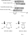
- Figure 1a is an illustration of an uplink timing advance in a cellular communication network.
- Figure 1 illustrates that there is a time delay from the point in time when either the RBS transmits in downlink or the UE transmits in uplink until the UE or the RBS receives the respective transmission.
- Figure 1a illustrates both that there is a delay from the point in time a transmission is sent until the point in time when the transmission is received, and that the point in time when the UE should transmit, or send, an uplink frame is relative a point in time when the UE receives a downlink frame.
- the time difference between the uplink transmission time and the downlink frame reception time is denoted timing advance.
- the timing advance can be described via different frameworks.
- timing advance is defined as an integer N TA times an LTE basic time unit T s that equals 1/(2048*15000) second, which in total gives a timing advance of N TA T s .
- the principle is applicable in other cellular communication networks.
- the transmission of an uplink radio frame shall start N TA T s seconds before the start of the corresponding downlink radio frame at the UE.
- the uplink timing is maintained by sending timing advance commands to the UE, which are based on estimated uplink timing of the UE.
- the UE will adjust the timing advance, by updating N TA based on the received timing advance commands.
- Figure 1b illustrates two situations where the estimated uplink timing is inadequate.
- the ⁇ t is negative, indicating that the uplink is received too early. This implies that N TA T s is too long a time, and the network will send an uplink timing advance command to the UE to decrease N TA .
- the ⁇ t is positive, indicating that the uplink is received too late. This implies that N TA T s is a too short a time, and the network will send an uplink timing advance command to the UE to increase N TA .
- Figure 1b left hand side, illustrates a situation where the UE 150 transmits too early in relation to the downlink transmission from the RBS 160. In this situation, the UE will have to adjust its uplink transmission so that it is delayed with ⁇ t so that it is time aligned with the RBS's downlink transmission.
- Figure 1b right hand side, illustrates a situation where the UE 150 transmits too late in relation to the downlink transmission from the RBS 160. In this situation, the UE will have to adjust its uplink transmission so that it is moved forward in time with ⁇ t so that it is time aligned with the RBS's downlink transmission.
- the RBS 160 may send quantized corrections to the UE 150.
- timing alignment is restarted every time a UE changes its serving RBS, or serving cell, and while connected to the RBS, or cell, timing alignment is maintained by regular relative corrections of a timing advance with respect to the serving RBS, or serving cell, downlink reception by the UE.
- the UE When a UE moves around having both an uplink and a downlink radio link established to a first RBS, the UE may enter or be located in an area in which two cells, or coverage areas of the first RBS and a neighbouring RBSs, meet. In certain scenarios, the UE may establish an uplink radio link to the neighbouring RBS and still keep the downlink radio link to the first RBS. Since the first RBS and the neighbouring RBS are not the same, the timing advance may be different. Since the timing advance is relative the downlink transmission, a problem arises when the uplink and downlink radio links are established to different RBSs.
- WO 2011/100673 A1 discloses in its Figure 12 and supporting text an arrangement of a first RBS and a neighbouring RBS which are in communication with a UE. All information including timing advance is exchanged between the first RBS and the neighbouring RBS. When a pair of associated UL and DL carriers used by the UE are connected to the first RBS and the neighbouring RBS respectively, the UE administers timing advances specific to each of the first RBS and the neighbouring RBS, maintaining separate timing advances for each RBS.
- US 2011/080896 A1 discloses an RBS in communication with a UE in which the UE maintains separate UL and DL timing advances for its communication with the RBS.
- an RBS is provided according to the independent apparatus claim.
- the respective method performed by the respective RBS may have several advantages. They provide an alternative mechanism for acquisition and configuration of the proper uplink transmission timing to be used by the UE. They enable a UE to be "served" by two different RBSs and still use a proper uplink transmission timing.
- the methods/RBSs may be also beneficial during uplink configurations, especially when shifting uplink reception points between different nodes, e.g. a handover of the uplink radio link from RBS A to RBS B. In such an uplink handover situation, the methods/RBSs in particular provide the advantage that the UE may keep the previous source of the downlink transmissions, i.e.
- RBS A and still use the downlink transmissions as the reference for the uplink transmission timing, despite the fact that the sender of the downlink transmissions (RBS A) and the receiver of the uplink transmissions (RBS B) are different nodes.
- Another advantage is that it is possible to complete handover from RBS A to RBS B (or from a first RBS to a second RBS) without a random access procedure towards the second RBS, i.e. RBS B, which does not serve the UE in downlink.
- the handover may further be performed without data transmission interruption.
- an RBS operable in a cellular communication network and a method therein for transmitting time alignment configuration to a UE are provided. Further, an RBS operable in a cellular communication network and a method therein for providing a timing related parameter relevant for the UE to a neighbouring RBS are provided. The time alignment configuration is determined by the RBS based on information received a neighbouring RBS, which receives uplink transmission(s) from the UE.
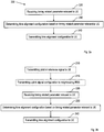
- FIG. 2a illustrates the method performed by the RBS comprising receiving 220, from a neighbouring RBS, a timing related parameter relevant for the UE as estimated by the neighbouring RBS, and determining 230 a time alignment configuration based on the received timing related parameter(s).
- the method further comprises transmitting 240, to the UE, the determined time alignment configuration.
- the RBS is operable in a cellular communication network and it is responsible for transmitting time alignment configuration to the UE.
- the RBS has at least one neighbouring RBS.
- the RBS responsible for transmitting time alignment configuration to the UE may hereinafter be referred to as RBS A and the neighbouring RBS may be referred to as RBS B.
- the RBS A receives at least one timing related parameter relevant for the UE from the neighbouring RBS, i.e. RBS B.
- the timing related parameter has been estimated by the neighbouring RBS.
- the timing related parameter relevant for the UE is a measure of timing situation information. How the RBS B has estimated the timing related parameter(s) will be described in more detail below.
- An example of a timing related parameter is uplink received timing relative a desired uplink timing, this will be explained below.
- the RBS A may determine a time alignment configuration based on the received timing related parameter(s).
- the RBS A is informed by means of the at least one timing related parameter when the UE is transmitting an uplink frame or uplink transmission in relation to a reference time of the neighbouring RBS, i.e. RBS B.
- the at least one timing related parameter may inform the RBS A when the UE should transmit any uplink frame in order for the RBS B to receive it properly.
- the RBS A may determine the time alignment configuration based on when in time in relation to the downlink transmission of the RBS A.
- the RBS A determines when in time the UE should transmit any uplink frame, relative a downlink transmission from the RBS A, in order for the RBS B to receive the transmitted uplink frame properly.
- the RBS A then transmits the determined time alignment configuration to the UE.
- the RBS A has an internal reference time, which controls when the RBS A transmits in downlink and should receive any uplink transmission. Therefore, the time alignment configuration can be said to be relative the reference time of RBS A, which controls the downlink transmissions from the RBS A.
- the method performed by the RBS may have several advantages.
- the method provides an alternative mechanism for acquisition and configuration of the proper uplink transmission timing to be used by the UE. It enables a UE to be "served" by two different RBSs and still use a proper uplink transmission timing.
- the method may be also beneficial during uplink configurations, especially when shifting uplink reception points between different nodes, e.g. a handover of the uplink radio link from RBS A to RBS B. In such an uplink handover situation, the method in particular provides the advantage that the UE may keep the previous source of the downlink transmissions, i.e.
- RBS A and still use the downlink transmissions as the reference for the uplink transmission timing, despite the fact that the sender of the downlink transmissions (RBS A) and the receiver of the uplink transmissions (RBS B) are different nodes.
- Another advantage is that it is possible to complete handover from RBS A to RBS B (or from a first RBS to a second RBS) without a random access procedure towards the second RBS, i.e. RBS B, which does not serve the UE in downlink.
- the handover may further be performed without data transmission interruption.
- the determined time alignment configuration comprises an indication to the UE that the time alignment configuration is based on the received timing related parameter(s) with respect to a transmitted pilot or reference signal from the neighbouring RBS.
- any downlink transmission is controlled by an internal time reference of the RBS.
- Any downlink transmission e.g. downlink transmission of a data frame or the transmission by a pilot or reference signal.
- the neighbouring RBS, RBS B also transmits a pilot or reference signal which the UE can "hear", or receive.
- the UE must know which reference to align after, i.e. in relation to which reference shall the UE apply the received time alignment configuration.
- the UE receives a downlink transmission from the RBS A having a first time reference associated with RBS A.
- the UE also receives a pilot or reference signal from RBS B having a second time reference associated with RBS B.
- the time alignment configuration comprises an indication to the UE which time reference to use when employing or applying the received time alignment configuration.
- the time alignment configuration comprises an indication to the UE that the UE shall employ or apply the time alignment configuration with respect to the pilot or reference signal received from the neighbouring RBS, RBS B.
- the RBS A may either have or obtain the information regarding the reference time of RBS B, e.g. RBS A and RBS B may communicate directly or indirectly via e.g. a node in a Radio Access Network, RAN, or via a node in a core network.
- the RBS A when the RBS A receives the timing related parameter relevant to the UE from the neighbouring RBS B, the reference time of RBS B is enclosed so that the RBS A may determine the time alignment configuration based on the received timing related parameter with respect to the reference timing of RBS B.
- the method further comprises transmitting 210 a pilot signal, reference signal or downlink transmission to the UE, wherein the time alignment configuration is based on the received timing related parameter(s) with respect to the transmitted pilot signal, reference signal or downlink transmission, wherein the determined time alignment configuration comprises an indication to the UE that the time alignment configuration is based on the received timing related parameter(s) with respect to the transmitted pilot, reference signal from the RBS or downlink transmission.
- the transmitted pilot signal, reference signal or downlink transmission to the UE may be used as a time reference for the UE when the UE employs or applies the time alignment configuration, as described above.
- the UE will receive the transmitted pilot signal, reference signal or downlink transmission and transmit in the uplink to the neighbouring RBS, RBS B.
- the RBS B estimates at least one timing related parameter relevant to the UE and transmits the estimated at least one timing related parameter to the RBS, RBS A.
- the RBS A receives the estimated at least one timing related parameter relevant to the UE and uses the parameter to determine a time alignment configuration based on the received parameter.
- the time alignment configuration is further based on the time reference of the RBS, RBS A.
- the time alignment configuration further comprises an indication to the UE that the UE shall apply or employ the time alignment configuration with respect to the transmitted pilot, reference signal from the RBS or the downlink transmission from the RBS, RBS A.
- the method further comprises transmitting 215, to the neighbouring RBS, signalling indicating which of an uplink Demodulation Reference Symbol, DM-RS, a Sounding Reference Symbol, SRS, and a Random Access, RA, preamble to use for estimating the timing related parameter(s) relevant for the UE.
- the neighbouring RBS, RBS B estimates the uplink reception time of a frame transmitted from the UE.
- the frame is a signal waveform, which may be an uplink DM-RS, an SRS or an RA preamble.
- the RBS A also transmits an uplink signal configuration to the UE in order to inform the UE about which signal waveform to use.
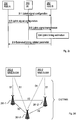
- FIG. 2c is a signalling diagram of an example of an RBS configuring uplink signalling.
- the RBS in this example is the RBS A.
- RBS A 250 which is the RBS responsible for sending time alignment configuration to the UE determines an uplink signal configuration.
- the uplink signal configuration comprises information on which signal waveform to use, DM-RS, an SRS or an RA preamble, and sends 2:1 the uplink signal configuration to the neighbouring RBS, RBS B 252.
- the RBS A 250 also sends 2:2 the uplink signal configuration to the UE 260.
- the UE 260 and the neighbouring RBS B 252 have the same information about which signal waveform to be used for uplink transmission from the UE 521 to the neighbouring RBS B 252.
- the UE 521 sends 2:3 an uplink signal transmission to the neighbouring RBS B 252.
- the neighbouring RBS B 252 performs a 2:4 uplink timing estimation comprising estimating at least one timing related parameter relevant for the UE based on the received uplink signal transmission.
- the neighbouring RBS B 252 then sends 2:5 the estimated timing related parameter relevant for the UE to the RBS A 250. This last action results in the RBS A 250 receiving the at least one timing related parameter relevant for the UE as estimated by the neighbouring RBS B 252 as is illustrated in figure 2a in action 220.
- the UE may then employ the signal waveform for a subsequent uplink transmission. Since the neighbouring RBS, RBS B, receives the signalling from RBS A indicating which of an uplink DM-RS, an SRS, and an RA preamble to use for estimating the timing related parameter(s) relevant for the UE, the neighbouring RBS, RBS B, is enabled to use the correct signal waveform, i.e. the signal waveform used by the UE for the uplink transmission, for estimating the timing related parameter(s) relevant for the UE.
- the neighbouring RBS, RBS B is enabled to use the correct signal waveform, i.e. the signal waveform used by the UE for the uplink transmission, for estimating the timing related parameter(s) relevant for the UE.
- the neighbouring RBS B is thus enabled to estimate the uplink timing situation of the UE, while the UE is served in the downlink by the RBS A.
- the uplink timing situation is estimated relative the uplink transmission time in the UE, wherein the uplink transmission time in the UE is related to the reception time of a downlink transmission, or a pilot signal or a reference signal from the RBS A.
- a reception time of a downlink transmission is the reception of the start of a downlink radio frame from the RBS A.
- the timing related parameter(s) relevant for the UE is received from the neighbouring RBS by means of an X2 interface.
- RBS A and RBS B may communicate directly by means of an X2-interface.
- the timing related parameter(s) relevant for the UE may be transferred from RBS B to RBS A e.g. in a Handover Request Acknowledge message of the X2 Application Protocol (X2AP) or in a new X2AP message.
- X2AP X2 Application Protocol
- they may communicate indirectly e.g. via a Mobility management Entity, MME, and by means of an S1-interface.
- the timing related parameter(s) relevant for the UE may be transferred from RBS B to RBS A in a "container" that is opaque for the MME, i.e. which the MME does not try to interpret, but merely forwards between RBS B and RBS A.
- RBS B would include the container in a suitable S1 Application Protocol (S1AP) message to the MME, e.g. a Handover Request Acknowledge message.
- S1AP S1 Application Protocol
- the MME in turn would include the container in a suitable S1AP message when forwarding it to RBS A, for instance a Handover Command message.
- Timing related parameter(s) relevant for the UE it is also possible that two MMEs are involved in the forwarding of the timing related parameter(s) relevant for the UE, in case RBS A and RBS B are connected to different MMEs (or different MME pools). Then the timing related parameter(s) relevant for the UE would be transferred in a suitable control plane message of the General Packet Radio Service Tunnelling Protocol version 2 (i.e. a GTPv2-C message) across an S10 interface between the two MMEs.
- GTPv2-C message General Packet Radio Service Tunnelling Protocol version 2
- the RBS A and the neighbouring RBS B are employed in a GSM based communication system, wherein the RBS A and the neighbouring RBS B may not communicate directly, but indirectly via e.g. a Base Station Controller, BSC, by means of an Abis-interface or a Mobile Switching Centre, MSC.
- BSC Base Station Controller
- MSC Mobile Switching Centre
- the RBS A and the neighbouring RBS B are employed in a UMTS based communication system, wherein the RBS A and the neighbouring RBS B may not communicate directly, but indirectly via e.g. a Radio Network Controller, RNC by means of an lub-interface.
- RNC Radio Network Controller
- RBS B is evaluating the uplink timing related parameter, signals the information to RBS A, which communicates with the UE concerning uplink timing commands.
- FIG. 2d Examples of different communication networks and Radio Access Techniques, RATs, are schematically illustrated in figures 2d-f .
- An LTE based RAT is illustrated in figure 2d
- a GSM based RAT is illustrated in figure 2e
- a UMTS based RAT is illustrated in figure 2f .
- the timing related parameter(s) relevant for the UE is received from a BSC 271 comprised in a GSM EDGE Radio Access Network, GERAN, of the cellular communication network.
- GERAN GSM EDGE Radio Access Network
- the a timing related parameter relevant for the UE is received from an RNC 281 comprised in a Universal Terrestrial Radio Access Network, UTRAN of the cellular communication network.
- LTE is based on a rather flat architecture compared to GSM and UMTS systems.
- Each cell is served by an eNodeB or eNB ("RBS"), and handovers between cells can be handled either via the MME and the S1 interface, or directly between the eNBs via the X2 interface.
- RBSs also called Base Transceiver Stations, BTSs, or simply Base Stations, BSs, and NodeB or NB, respectively, are more hierarchical as the RBSs are not enabled to communicate directly but only via the BSC and RNC respectively.
- FIG. 2g is a schematic illustration of a management system architecture for LTE based communication networks or systems.
- the Node Elements, NE also referred to as RBSs or eNBs, are managed by a Domain Manager, DM, also referred to as the operation and support system, OSS.
- a DM may further be managed by a Network Manager, NM.
- Two NEs are interfaced by X2, whereas the interface between two DMs is referred to as Itf-P2P.
- the management system may configure the network elements, as well as receive observations associated to features in the network elements. For example, DM observes and configures NEs, while NM observes and configures DM, as well as NE via DM.
- the timing situation information transfer i.e. the at least one timing related parameter relevant for the UE as estimated by the neighbouring RBS B, from the neighbouring RBS B to the first RBS, RBS A
- the neighbouring RBS B may be realised via an X2 interface (or an evolved version thereof) or via a node in the core network (i.e. the concerned MME(s)) across the S1 interfaces in case of LTE.
- the neighbouring RBS B may identify the first RBS A from the DL first cell transmissions (e.g. the system information transmissions) either directly or as reported by served UEs.
- the neighbouring RBS B may have been configured with appropriate one or more RBSs via an Operation and Maintenance, OaM, system.
- the timing related parameter(s) relevant for the UE is received, via an S1 interface, from a core network to which the RBS and the neighbouring RBS are associated.
- transmitting 240, to the UE, the determined time alignment configuration is performed by means of a Radio Resource Control, RRC, protocol.
- RRC Radio Resource Control
- transmitting 240, to the UE, the determined time alignment configuration is performed by means of a Medium Access Control, MAC, protocol.
- the time alignment and timing advance signalling, i.e. the time alignment configuration, to the UE can be via a RRC, a MAC protocol, or any other protocol between an RBS (or another node in the RAN) and the UE.
- the time alignment configuration comprising time adjustment information may be included in an RRCConnectionReconfiguration message from the RBS A which is responsible for downlink transmission to the UE, and can be seen as a means for the RBS A to reconfigure the uplink timing advance, either relative to the current timing advance, a transmitted reference/pilot signal or via an absolute value.
- the time alignment configuration information may alternatively be included in a mobilityControllnfo, for example included in an RRCConnectionReconfiguration message, and may be seen as a means to configure the uplink for reception at a different node.
- the uplink timing advance can preferably be relative the RBS A in the downlink such that the timing advance is configured relative to a reception time of a DL transmission from the RBS A.
- this RBS may also be referred to as the first RBS, but it can also be the second RBS, i.e. the neighbouring RBS B, as a consequence of the reconfiguration.
- the reconfiguration message may also contain access information relevant for the neighbouring RBS B, possibly as received from the neighbouring RBS B.
- Such information may comprise an assigned uplink resource for communication with the neighbouring RBS B, a cell specific UE identifier to use for the uplink communication with the neighbouring RBS B (e.g. a C-RNTI), and information about coding, modulation, waveform, encryption etc.
- the first RBS, RBS A may also configure the timing advance in the UE via commands sent as MAC control elements. These may be either relative the current timing advance, a transmitted reference/pilot signal or a new timing advance in absolute terms.
- the UE may then adjust its timing advance e.g. with respect to the downlink timing from the RBS A downlink.
- the Timing Advance, TA, commands may also be signalled via some other interface between the RBS A and the UE.
- the RBS A may restart the uplink timing outside the random access procedure.
- An example is the case when the uplink of a specific UE is detected at the neighbouring RBS B and is considered to be a more favourable uplink than the uplink to the RBS A.
- the RBS A restarts the uplink timing advance of the UE based on timing information (the at least one timing related parameter relevant for the UE) from the neighbouring RBS B in order to make the uplink timing advance relevant for the second neighbouring RBS B uplink.
- the time alignment configuration comprises a new timing advance in absolute terms.
- the time alignment configuration comprises a new timing advance in absolute terms.
- the UE will adjust the timing of a subsequent uplink transmission relevant a previous uplink transmission according to the timing advance in absolute terms.
- the timing advance in absolute terms may inform the UE to adjust its uplink timing by e.g. delaying it 5 microseconds relative the uplink timing for a previous uplink transmission.
- the timing advance in absolute terms may inform the UE to adjust its uplink timing by e.g. moving it forward 10 milliseconds relative the uplink timing for a previous uplink transmission.
- Embodiments herein also relate to a method performed by an RBS, RBS B, operable in a cellular communication network, for providing a timing related parameter relevant for a UE to a neighbouring RBS, RBS A.
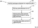
- Figure 3a illustrates the method 300 comprising receiving 310 from the UE, an uplink transmission; and estimating 320 a timing related parameter relevant for the UE based on the received uplink transmission.
- the method further comprises transmitting 330, to a neighbouring RBS, RBS A, the estimated timing related parameter relevant for the UE for enabling the neighbouring RBS, RBS A, to determine a timing alignment configuration based on the estimated timing related parameter.
- the RBS B is not responsible for transmitting downlink transmissions to the UE and hence, the RBS B does not send, or transmit, timing alignment configuration to the UE.
- the UE is instead served in downlink by the neighbouring RBS A.
- RBS B can be said to serve the UE in uplink, since the transmissions in uplink from the UE is received by the RBS B.
- RBS B receives an uplink transmission from the UE.
- the RBS B estimates the timing related parameter (or the at least one timing related parameter) relevant for the UE based on the received uplink transmission. In one example, the estimation comprises comparing the reception time of the uplink transmission, the uplink reception time, to a reference timing of RBS B.
- the RBS B determines this difference, which can be positive or negative as has been described above in conjunction with figure 1b .
- the RBS B may estimate the timing related parameter to be -0.005 seconds, which looking at figure 1b corresponds to the UE having transmitted the uplink transmission 0.005 too soon and needs to delay a subsequent uplink transmission by 0.005 seconds.
- the RBS B transmits the timing related parameter being 0.005 seconds to the neighbouring RBS A.
- the RBS A is enabled to determine a timing alignment configuration based on the estimated timing related parameter, which the RBS A will thereafter send to the UE as has been described above in conjunction with figures 2a-2g .
- the RBS B may compare the uplink reception time to a reference time or a desired uplink reception time as just described above.
- the uplink timing situation in this case comprises the uplink reception time or difference between the uplink reception time and the reference/desired uplink reception time.
- node timing information may also be considered as part of the timing situation.
- the node timing situation relates to an offset between a time reference of the RBS B and a time reference of a second neighbouring RBS not responsible for transmitting time alignment configuration to the UE.
- the offset is the difference in time between the start of a new frame at the RBS and the start of a new frame at the second neighbouring RBS.
- the method performed by RBS B for providing a timing related parameter relevant for the UE to a neighbouring RBS, RBS A has the same advantages as the method performed by the RBS A for transmitting time alignment configuration to a UE, since the two RBSs work together in order to provide the UE with the time alignment configuration.
- the method provides an alternative mechanism for acquisition and configuration of the proper uplink transmission timing to be used by the UE. It enables a UE to be "served" by two different RBSs and still use a proper uplink transmission timing.
- the method may be also beneficial during uplink configurations, especially when shifting uplink reception points between different nodes, e.g. a handover of the uplink radio link from RBS A to RBS B.
- the method in particular provides the advantage that the UE may keep the previous source of the downlink transmissions, i.e. RBS A, and still use the downlink transmissions as the reference for the uplink transmission timing, despite the fact that the sender of the downlink transmissions (RBS A) and the receiver of the uplink transmissions (RBS B) are different nodes.
- Another advantage is that it is possible to complete handover from RBS A to RBS B (or from a first RBS to a second RBS) without a random access procedure towards the second RBS, i.e. RBS B, which does not serve the UE in downlink.
- the handover may further be performed without data transmission interruption.
- estimating 220 the timing related parameter further comprises estimating the timing related parameter relevant for the UE based on the received uplink transmission in relation to a transmitted pilot signal or reference signal from the RBS to the UE.
- the transmitted pilot signal or reference signal from the RBS B to the UE may be depending on, or closely related to, the reference time.
- the RBS B may indicate, to the RBS A, when sending the at least one timing related parameter relevant for the UE to RBS B if the at least one timing related parameter is estimated in relation to the reference time of RBS B, or in relation to an uplink reception time,
- the received uplink transmission from the UE comprises at least one of a DM-RS, an SRS, and an RA preamble.
- the method further comprises receiving, from the neighbouring RBS A, signalling indicating which of the DM-RS, SRS and the RA preamble to use for estimating the timing related parameter(s) relevant for the UE.
- estimating 220 the timing related parameter(s) relevant for the UE based on the received uplink transmission comprises comparing the uplink reception time of the received uplink transmission to a reference uplink reception time.
- estimating 220 the timing related parameter(s) relevant for the UE is performed per UE or is performed for aggregated UEs which receive their time alignment configuration from the neighbouring RBS, RBS A.
- UEs in a cell overlap region of the first and second cells may trigger measurement reports including the first cell if being served by the second cell, and including the second cell if being served by the first cell. Thereby, a UE can be classified as a cell overlap region UE.
- the UE-specific timing situation estimation may then be performed aggregated for all, or a subset of all, UEs served by the RBS B and also are classified as cell overlap UEs.
- heterogeneous networks comprising both macro RBSs having relatively strong output power and corresponding large coverage areas or cells and low power RBSs having relatively weak output power and corresponding small coverage areas or cells, wherein the RBS A is a macro RBS and the RBS B is a low power RBS, all UEs being served in uplink by the RBS B having a small cell may have the same uplink timing situation.
- the reception of the uplink transmission from the UE is preceded by a handover of uplink transmission from the UE, from the neighbouring RBS, RBS A, to the RBS, RBS B, wherein a downlink transmission to the UE is continued to be handled by the neighbouring RBS, RBS A.
- the exchanged handover information may comprise timing situation information of respective RBS, wherein the estimation of the timing related parameter relevant for the UE at RBS B is based on handover information received from RBS A.
- the RBS B may compare the timing information as received by means of the handover information received from RBS A to a reference time of the RBS B, and determine a difference between the handover information received from RBS A and the reference time of the RBS B.
- the UE has an ongoing communication session with the RBS A, wherein RBS A is serving the UE in both uplink and downlink.
- the UE is moving towards RBS B.
- the uplink radio link is handed over to the RBS B, while RBS A so to say "keeps" the downlink radio link.
- the UE can be said to be served in downlink by RBS A and in uplink by RBS B.
- the UE may receive time alignment configuration so that the UE will transmit any uplink transmission with reference to the time alignment configuration with respect to RBS A.
- the time alignment configuration may be invalid, e.g. due to the distance from the UE to RBS B being different than the distance from the UE to RBS A or due to the RBS A and RBS B having different respective reference times.
- the time alignment configuration must be updated with respect to RBS B.
- the method further comprises receiving a downlink signal transmission from the neighbouring RBS, wherein estimating 220 the timing related parameter(s) relevant for the UE is further based on the received downlink signal transmission.
- the RBS B is equipped with receiving capabilities such that it can receive the downlink transmission from the neighbouring RBS A.
- the RBS is equipped with a UE component. This component may for example be used to scan the surroundings before the RBS B is active as an RBS to learn about neighbouring RBSs.
- the UE component of RBS B may be used to determine the timing situation in the vicinity of the RBS B, and this information can be used to predict what the timing situation will be for served UEs, if it can be assumed that they are close to the RBS B.
- Estimating 220, 225 the timing related parameter(s) relevant for the UE may be performed regularly, in response to a request from the neighbouring RBS A, during or following a handover of the uplink transmission of the UE from the neighbouring RBS A to the RBS B.
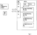
- Embodiments herein also relate to an RBS operable in a cellular communication network, adapted for transmitting time alignment configuration to a UE. Exemplifying embodiment will now be described with reference to figure 4 .
- the RBS has the same technical features, objects and advantages as the method performed by the RBS as described above. The RBS will only be described in brief in order to avoid unnecessary repetition.
- FIG. 4 illustrates the RBS 400, RBS A, operable in a cellular communication network, adapted for transmitting time alignment configuration to a UE 430 comprising a receiving unit 403 adapted for receiving, from a neighbouring RBS, RBS B, a timing related parameter relevant for the UE as estimated by the neighbouring RBS; and a determining unit 404 adapted for determining a time alignment configuration based on the received timing related parameter(s).
- the RBS A 400 further comprises a transmitting unit 402 adapted for transmitting, to the UE, the determined time alignment configuration.
- the RBS 400 has the same advantages as the method 200 performed by the RBS 400.
- the RBS provides an alternative mechanism for acquisition and configuration of the proper uplink transmission timing to be used by the UE. It enables a UE to be "served" by two different RBSs and still use a proper uplink transmission timing.
- the method may be also beneficial during uplink configurations, especially when shifting uplink reception points between different nodes, e.g. a handover of the uplink radio link from RBS A to RBS B. In such an uplink handover situation, the method in particular provides the advantage that the UE may keep the previous source of the downlink transmissions, i.e.
- RBS A and still use the downlink transmissions as the reference for the uplink transmission timing, despite the fact that the sender of the downlink transmissions (RBS A) and the receiver of the uplink transmissions (RBS B) are different nodes.
- Another advantage is that it is possible to complete handover from RBS A to RBS B (or from a first RBS to a second RBS) without a random access procedure towards the second RBS, i.e. RBS B, which does not serve the UE in downlink.
- the handover may further be performed without data transmission interruption.
- the determined time alignment configuration comprises an indication to the UE 430 that the time alignment configuration is based on the received timing related parameter(s) with respect to a transmitted pilot or reference signal from the neighbouring RBS.
- the transmitting unit 402 further is adapted for transmitting a pilot signal, reference signal or downlink transmission to the UE, wherein the determining unit (404) is adapted to determine the time alignment configuration based on the received timing related parameter(s) with respect to the transmitted pilot signal, reference signal or downlink transmission, wherein the determined time alignment configuration comprises an indication to the UE that the time alignment configuration is based on the received timing related parameter(s) with respect to the transmitted pilot, reference signal from the RBS or downlink transmission.
- the transmitting unit (402) further is adapted for transmitting, to the neighbouring RBS, signalling indicating which of a Demodulation Reference Symbol, DM-RS, a Sounding Reference Symbol, SRS, and a Random Access, RA, preamble to use for estimating the timing related parameter(s) relevant for the UE.
- the receiving unit further is adapted to receive the timing related parameter(s) relevant for the UE from the neighbouring RBS by means of an X2 interface.
- the receiving unit further is adapted to receive the timing related parameter(s) relevant for the UE, via an S1 interface, from a core network to which the RBS and the neighbouring RBS are associated.
- transmitting unit 402 is adapted for transmitting, to the UE, the determined time alignment configuration by means of an RRC protocol.
- transmitting unit (402) is adapted for transmitting, to the UE, the determined time alignment configuration is performed by means of a MAC protocol.
- the time alignment configuration comprises a new timing advance in absolute terms.
- Embodiments herein also relate to an RBS operable in a cellular communication network, adapted for providing a timing related parameter relevant for a UE to a neighbouring RBS. Exemplifying embodiment will now be described with reference to figure 5 .
- the RBS has the same technical features, objects and advantages as the method performed by the RBS as described above. The RBS will only be described in brief in order to avoid unnecessary repetition.
- FIG. 5 illustrates the RBS 500, RBS A, operable in a cellular communication network, adapted for providing a timing related parameter relevant for a UE to a neighbouring RBS comprising a receiving unit 522 adapted for receiving, from the UE, an uplink transmission, and an estimating unit 523 adapted for estimating a timing related parameter relevant for the UE based on the received uplink transmission.
- the RBS 500 further comprises a transmitting unit 524 adapted for transmitting, to a neighbouring RBS, the estimated timing related parameter relevant for the UE for enabling the neighbouring RBS to determine a timing alignment configuration based on the estimated timing related parameter.
- the RBS 500 has the same advantages as the method 300 performed by the RBS 500.
- the RBS provides an alternative mechanism for acquisition and configuration of the proper uplink transmission timing to be used by the UE. It enables a UE to be "served" by two different RBSs and still use a proper uplink transmission timing.
- the method may be also beneficial during uplink configurations, especially when shifting uplink reception points between different nodes, e.g. a handover of the uplink radio link from RBS A to RBS B. In such an uplink handover situation, the method in particular provides the advantage that the UE may keep the previous source of the downlink transmissions, i.e.
- RBS A and still use the downlink transmissions as the reference for the uplink transmission timing, despite the fact that the sender of the downlink transmissions (RBS A) and the receiver of the uplink transmissions (RBS B) are different nodes.
- Another advantage is that it is possible to complete handover from RBS A to RBS B (or from a first RBS to a second RBS) without a random access procedure towards the second RBS, i.e. RBS B, which does not serve the UE in downlink.
- the handover may further be performed without data transmission interruption.
- the estimating unit 523 further is adapted to estimate the timing related parameter by estimating the timing related parameter relevant for the UE 530 based on the received uplink transmission in relation to a transmitted pilot signal or reference signal from the RBS B to the UE.
- the received uplink transmission from the UE comprises at least one of a DM-RS, an SRS, and an RA preamble.
- the receiving unit 522 further is adapted for receiving, from the neighbouring RBS, signalling indicating which of the DM-RS, SRS and the RA preamble to use for estimating the timing related parameter(s) relevant for the UE.
- the estimating unit 532 is adapted for estimating the timing related parameter(s) relevant for the UE based on the received uplink transmission by comparing the uplink reception time of the received uplink transmission to a reference uplink reception time.
- the estimating unit 532 is adapted for estimating the timing related parameter(s) relevant for the UE per UE or for aggregated UEs which receive their time alignment configuration from the neighbouring RBS.
- the reception of the uplink transmission from the UE is preceded by a handover of uplink transmission from the UE, from the neighbouring RBS to the RBS, wherein a downlink transmission to the UE is continued to be handled by the neighbouring RBS.
- the receiving unit 522 further is adapted for receiving a downlink signal transmission from the neighbouring RBS, wherein the estimating unit 532 is adapted for estimating the timing related parameter(s) relevant for the UE also based on the received downlink signal transmission.
- the respective methods and RBSs may be applied to heterogeneous networks comprising both macro RBSs having relatively strong output power and corresponding large coverage areas or cells and low power RBSs having relatively weak output power and corresponding small coverage areas or cells, wherein the RBS A is a macro RBS and the RBS B is a low power RBS.
- a schematic illustration of a macro RBS and a low power RBS is shown in figure 8.
- Figure 8 illustrates one macro RBS A 801 and one low power RBS B 802.
- Figure 8 also illustrates a feature in heterogeneous networks called cell expansion, wherein the coverage area, or cell, of the low power RBS B 802 is expanded.
- the output power of the low power RBS B 802 is relatively small compared to the output power of the macro RBS A 801.
- a UE possible still being relatively close to the low power RBS B 802 it might be preferable to be served in uplink by the low power RBS B 802.
- the RBS B When the RBS B has a limited coverage area, or cell, which may be the case e.g. in a heterogeneous network if the RBS B is a low power RBS; then the same uplink timing can be used by all UEs in the second cell coverage area. Therefore, the uplink timing can be estimated over time since it can be considered static.
- the determination that the second cell have sufficient limited coverage may be automatic, or via configuration in OaM.
- An automatic function may disclose that the coverage is sufficiently limited by observing the timing advance procedure of its served UEs. If the observed timing advance is the same (or at least a pre-determined fraction of the observations are the same), then the cell coverage is considered sufficiently limited.
- the same timing advance may be 0 for all, or the pre-determined fraction, or the UEs served by the second cell.
- the RBS B uses a determined sufficient limited coverage as the uplink timing situation.
- the determined same observed timing advance may be included in the uplink timing situation.
- the RBS B estimates the uplink timing situation based on a reception timing of DL transmissions from the first cell.
- the reception timing may be estimated regularly or only once, for example when the RBS B was installed.
- the estimated reception time can be related to the RBS A downlink time reference, for example the start of a downlink radio frame.
- the RBS A may reconfigure the UE to apply the timing advance in relation to the RBS A DL reception time or the RBS B DL reception time.
- the RBS A may also transfer its serving role towards the UE from the RBS A to the RBS B and back. Then some different transfers of downlink reference and uplink reception points are illustrated in figure 9 . All these transfers will result in a need for an abrupt change of the uplink timing alignment.
- One alternative is to rely on incremental changes, so that the uplink timing alignment gradually will adapt to the needs after the transition.
- more accurate uplink timing alignment control can be obtained if the UE can be informed directly about the new downlink reference and uplink reception situation.
- Figure 9 indicates the needed uplink timing advance after the transition in each of the combinations of downlink reference and uplink reception point. Note that the transition from RBS A being both downlink reference and uplink reception point, to RBS B being both downlink reference and uplink reception point corresponds to a traditional handover between two different base stations.
- the methods and the RBSs described above may be employed in different types of communication networks.
- Most wireless communication systems benefit to some extent from time alignment across radio links. Examples of possible benefits are a more time aligned processing of signals, and better suppression of interference from other radio links.
- these benefits can be observed in any radio access technology, such as LTE Frequency Division Duplex, FDD, and LTE Time Division Duplex, TDD, other RATs of the 3 rd Generation Partnership Project, 3GPP, family, e.g. UMTS/High Speed Packet Access, HSPA, and/or GSM/ General Packet Radio Services, GPRS/ Enhanced Data Rate for Global Evolution, EDGE, and non-3GPP RATs, e.g.
- IEEE 802.11x family (where "x” may be e.g. “a”, “b”, “g” or “n") RATs or 3GPP2 RATs, e.g. Code Division Multiple Access, CDMA, 2000.
- x may be e.g. "a”, “b”, “g” or “n”
- 3GPP2 RATs e.g. Code Division Multiple Access, CDMA, 2000.
- all RBSs are assumed to employ the same RAT, e.g. a future release of 3GPP LTE, e.g. release 12 (or later).
- RRUs Remote Radio Units
- baseband hotels where multiple baseband processing units are located at a semi-central site.
- RRUs Remote Radio Units
- baseband hotels where multiple baseband processing units are located at a semi-central site.
- the same location is often covered (i.e. within the radio transmission and reception coverage area) by more than one cell and RBS or access point.
- Low power RBSs are often deployed to provide greater capacity in hotspot areas with dense user population and intense wireless communication, while macro RBSs provide the overall wide area coverage.
- a layered cell architecture is provided, e.g. consisting of a macro cell layer (or macro layer) and a low power cell layer (or low power layer).
- Pico and femto RBSs both being examples of different low power RBSs, as well as RRUs may also be deployed to improve coverage in locations which are poorly covered by the macro cell layer, e.g. indoors.
- RBSs have different transmission power (including pilot power), but about the same uplink radio conditions, there are areas in the service area, where the RBS, or cell, with the higher pilot and transmission power is more attractive to use for downlink communication than the RBS, or cell, with lower power, while the RBS with lower power is more attractive than the RBS with higher power for uplink communication.
- This is often referred to as UL/DL imbalance.
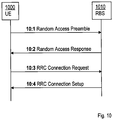
- the RA procedure in LTE is a four-phase procedure as illustrated in figure 10 .
- the RBS A 400 is also illustrated comprising a receiving unit 411 and a transmitting unit 412. Through these two units, the RBS A 400 is adapted to communicate with other nodes and/or entities in the wireless communication network.
- the receiving unit 411 may comprise more than one receiving arrangement.
- the receiving unit may be connected to both a wire and an antenna, by means of which the RBS A 400 is enabled to communicate with other nodes and/or entities in the wireless communication network.
- the transmitting unit 412 may comprise more than one transmitting arrangement, which in turn are connected to both a wire and an antenna, by means of which the RBS A 400 is enabled to communicate with other nodes and/or entities in the wireless communication network.
- the RBS A 400 further comprises a memory 401 for storing data.
- the RBS A 400 is illustrated comprising a control or processing unit 405 which in turns is connected to the different units 402-404. It shall be pointed out that this is merely an illustrative example and the RBS A 400 may comprise more, less or other units or modules which execute the functions of the RBS A 400 in the same manner as the units illustrated in figure 4 .
- figure 4 merely illustrates various functional units in the RBS A 400 in a logical sense.
- the functions in practice may be implemented using any suitable software and hardware means/circuits etc.
- the embodiments are generally not limited to the shown structures of the RBS A 400 and the functional units.
- the previously described exemplary embodiments may be realised in many ways.
- one embodiment includes a computer-readable medium having instructions stored thereon that are executable by the control or processing unit 405 for executing the method steps in the RBS A 400.
- the instructions executable by the computing system and stored on the computer-readable medium perform the method steps of the RBS A 400 as set forth in the claims.
- the RBS B 500 is also illustrated comprising a receiving unit 511 and a transmitting unit 512.
- the RBS B 500 is adapted to communicate with other nodes and/or entities in the wireless communication network.
- the receiving unit 511 may comprise more than one receiving arrangement.
- the receiving unit may be connected to both a wire and an antenna, by means of which the RBS B 500 is enabled to communicate with other nodes and/or entities in the wireless communication network.
- the transmitting unit 512 may comprise more than one transmitting arrangement, which in turn are connected to both a wire and an antenna, by means of which the RBS B 500 is enabled to communicate with other nodes and/or entities in the wireless communication network.
- the RBS B 500 further comprises a memory 521 for storing data. Further, the RBS B 500 is illustrated comprising a control or processing unit 525 which in turns is connected to the different units 522-524. It shall be pointed out that this is merely an illustrative example and the RBS B 500 may comprise more, less or other units or modules which execute the functions of the RBS B 500 in the same manner as the units illustrated in figure 5 .
- figure 4 merely illustrates various functional units in the RBS B 500 in a logical sense.
- the functions in practice may be implemented using any suitable software and hardware means/circuits etc.
- the embodiments are generally not limited to the shown structures of the RBS B 500 and the functional units.
- the previously described exemplary embodiments may be realised in many ways.
- one embodiment includes a computer-readable medium having instructions stored thereon that are executable by the control or processing unit 525 for executing the method steps in the RBS B 500.
- the instructions executable by the computing system and stored on the computer-readable medium perform the method steps of the RBS B 500 as set forth in the claims.
- FIG. 6 schematically shows an embodiment of an arrangement in an RBS A 600.
- a processing unit 606 e.g. with a DSP (Digital Signal Processor).
- the processing unit 606 may be a single unit or a plurality of units to perform different actions of procedures described herein.
- the arrangement in the RBS A 600 may also comprise an input unit 602 for receiving signals from other entities, and an output unit 604 for providing signal(s) to other entities.
- the input unit and the output unit may be arranged as an integrated entity or as illustrated in the example of figure 4 , as one or more interfaces 411/412.
- the arrangement in the RBS A 600 comprises at least one computer program product 608 in the form of a non-volatile memory, e.g. an EEPROM (Electrically Erasable Programmable Read-Only Memory), a flash memory and a hard drive.
- the computer program product 608 comprises a computer program 610, which comprises code means, which when executed in the processing unit 606 in the arrangement in the RBS A 600 causes the arrangement in the RBS A 600 to perform the actions e.g. of the procedure described earlier in conjunction with figure 2a .
- the computer program 610 may be configured as a computer program code structured in computer program modules 610a-610e.
- the code means in the computer program of the arrangement in the RBS A 600 comprises a receiving unit, or module, for receiving, from a neighbouring RBS, a timing related parameter relevant for the UE as estimated by the neighbouring RBS.
- the computer program further comprises a determining unit, or module, for determining a time alignment configuration based on the received timing related parameter(s).
- the computer program further comprises a transmitting unit, or module, for transmitting, to the UE, the determined time alignment configuration.
- the computer program modules could essentially perform the actions of the flow illustrated in figure 2a , to emulate the arrangement in an RBS A 600.
- the different computer program modules when executed in the processing unit 606, they may correspond to the units 402-404 of figure 4 .
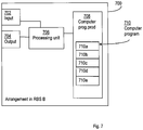
- FIG. 7 schematically shows an embodiment of an arrangement in an RBS B 700.
- a processing unit 706 e.g. with a DSP (Digital Signal Processor).
- the processing unit 706 may be a single unit or a plurality of units to perform different actions of procedures described herein.
- the arrangement in the RBS B 700 may also comprise an input unit 702 for receiving signals from other entities, and an output unit 704 for providing signal(s) to other entities.
- the input unit and the output unit may be arranged as an integrated entity or as illustrated in the example of figure 5 , as one or more interfaces 511/512.
- the arrangement in the RBS B 700 comprises at least one computer program product 708 in the form of a non-volatile memory, e.g. an EEPROM (Electrically Erasable Programmable Read-Only Memory), a flash memory and a hard drive.
- the computer program product 708 comprises a computer program 710, which comprises code means, which when executed in the processing unit 706 in the arrangement in the RBS B 700 causes the arrangement in the RBS B 700 to perform the actions e.g. of the procedure described earlier in conjunction with figure 3a .
- the computer program 710 may be configured as a computer program code structured in computer program modules 710a-710e.
- the code means in the computer program of the arrangement in the RBS B 700 comprises a receiving unit, or module, for receiving, from a UE, an uplink transmission.
- the computer program further comprises an estimating unit, or module, for estimating a timing related parameter relevant for the UE based on the received uplink transmission.
- the computer program further comprises a transmitting unit, or module, for transmitting, to a neighbouring RBS, the estimated timing related parameter relevant for the UE for enabling the neighbouring RBS to determine a timing alignment configuration based on the estimated timing related parameter.
- the computer program modules could essentially perform the actions of the flow illustrated in figure 3a , to emulate the arrangement in the RBS B 700.
- the different computer program modules when executed in the processing unit 706, they may correspond to the units 522-524 of figure 5 .
- code means in the respective embodiments disclosed above in conjunction with figures 2a and 3a are implemented as computer program modules which when executed in the respective processing unit causes the RBS A and the RBS B respectively to perform the actions described above in the conjunction with figures mentioned above, at least one of the code means may in alternative embodiments be implemented at least partly as hardware circuits.
- the processor may be a single CPU (Central processing unit), but could also comprise two or more processing units.
- the processor may include general purpose microprocessors; instruction set processors and/or related chips sets and/or special purpose microprocessors such as ASICs (Application Specific Integrated Circuit).
- the processor may also comprise board memory for caching purposes.
- the computer program may be carried by a computer program product connected to the processor.
- the computer program product may comprise a computer readable medium on which the computer program is stored.
- the computer program product may be a flash memory, a RAM (Random-access memory) ROM (Read-Only Memory) or an EEPROM, and the computer program modules described above could in alternative embodiments be distributed on different computer program products in the form of memories within the RBS A and the RBS B respectively.
Landscapes
- Engineering & Computer Science (AREA)
- Signal Processing (AREA)
- Computer Networks & Wireless Communication (AREA)
- Mobile Radio Communication Systems (AREA)
Claims (14)
- Verfahren (200), das von einer Funkbasisstation, RBS, durchgeführt wird, die in einem zellularen Kommunikationsnetzwerk betrieben werden kann, zum Senden einer Zeitanpassungskonfiguration an eine UE, wobei das Verfahren umfasst:- Empfangen (220) eines zeitbezogenen Parameters, der für die UE relevant ist, wie durch eine benachbarte RBS geschätzt, von der benachbarten RBS,- Bestimmen (230) einer Zeitanpassungskonfiguration basierend auf dem empfangenen zeitbezogenen Parameter, und- Senden (240) der bestimmten Zeitanpassungskonfiguration an die UE,wobei die bestimmte Zeitanpassungskonfiguration eine Angabe für die UE umfasst, dass die Zeitanpassungskonfiguration auf dem empfangenen zeitbezogenen Parameter in Bezug auf ein gesendetes Pilot- oder Referenzsignal von der benachbarten RBS basiert.
- Verfahren (200) nach Anspruch 1, ferner umfassend ein Senden (210) eines Pilotsignals, eines Referenzsignals oder einer Downlink-Übertragung an die UE, wobei die Zeitanpassungskonfiguration auf dem empfangenen zeitbezogenen Parameter in Bezug auf das gesendete Pilotsignal, das gesendete Referenzsignal oder die gesendete Downlink-Übertragung basiert, wobei die bestimmte Zeitanpassungskonfiguration eine Angabe für die UE umfasst, dass die Zeitanpassungskonfiguration auf dem empfangenen zeitbezogenen Parameter in Bezug auf das gesendete Pilot- oder Referenzsignal von der RBS oder die gesendete Downlink-Übertragung basiert.
- Verfahren (200) nach einem der Ansprüche 1 bis 2, ferner umfassend ein Senden (215) von Signalisierung an die benachbarte RBS, die angibt, welches von einem Demodulationsreferenzsymbol, DM-RS, einem Sondierungsreferenzsymbol, SRS, und einer Direktzugriffs, RA,-Präambel zum Schätzen der/des für die UE relevanten zeitbezogenen Parameter(s) verwendet werden soll.
- Verfahren (300) nach einem der vorhergehenden Ansprüche, wobei das Verfahren ferner umfasst, dass die benachbarte Basisstation:- eine Uplink-Übertragung von der UE empfängt (310),- den für die UE relevanten zeitbezogenen Parameter basierend auf der empfangenen Uplink-Übertragung schätzt (320), und- den für die UE relevanten geschätzten zeitbezogenen Parameter an die RBS sendet (330), um die RBS zum Bestimmen der Zeitanpassungskonfiguration zu befähigen.
- Verfahren (300) nach Anspruch 4, wobei das Schätzen (220) des zeitbezogenen Parameters ferner ein Schätzen des für die UE relevanten zeitbezogenen Parameters basierend auf der empfangenen Uplink-Übertragung in Bezug auf ein von der RBS an die UE gesendetes Pilotsignal oder Referenzsignal umfasst.
- Verfahren (300) nach Anspruch 4 oder 5, wobei die Uplink-Übertragung von der UE, die durch die benachbarte Basisstation empfangen wird, ein Demodulationsreferenzsymbol, DM-RS, ein Sondierungsreferenzsymbol, SRS, und/oder eine Direktzugriffs, RA,-Präambel umfasst.
- Verfahren (300) nach Anspruch 6, ferner umfassend, dass die benachbarte Basisstation Signalisierung von der RBS empfängt, die angibt, welches von dem DM-RS, dem SRS und der RA-Präambel zum Schätzen des für die UE relevanten zeitbezogenen Parameters verwendet werden soll.
- Verfahren (300) nach einem der Ansprüche 5 bis 7, wobei das Schätzen (220) des für die UE relevanten zeitbezogenen Parameters basierend auf der empfangenen Uplink-Übertragung ein Vergleichen der Uplink-Empfangszeit der empfangenen Uplink-Übertragung mit einer Uplink-Referenzempfangszeit umfasst.
- Funkbasisstation, RBS, (400), die in einem zellularen Kommunikationsnetzwerk betrieben werden kann und zum Senden von Zeitanpassungskonfiguration an eine Benutzereinrichtung, UE, (430) ausgelegt ist, wobei die RBS umfasst:- eine Empfangseinheit (403), die zum Empfangen (403) eines für die UE relevanten zeitbezogenen Parameters, wie durch eine benachbarte RBS geschätzt, von der benachbarten RBS ausgelegt ist,- eine Bestimmungseinheit (404), die zum Bestimmen einer Zeitanpassungskonfiguration basierend auf dem empfangenen zeitbezogenen Parameter ausgelegt ist, und- eine Sendeeinheit (402), die zum Senden der bestimmten Zeitanpassungskonfiguration an die UE ausgelegt ist,wobei die bestimmte Zeitanpassungskonfiguration eine Angabe für die UE umfasst, dass die Zeitanpassungskonfiguration auf dem empfangenen zeitbezogenen Parameter in Bezug auf ein gesendetes Pilot- oder Referenzsignal von der benachbarten RBS basiert.
- Funkbasisstation, RBS, (400) nach Anspruch 9 in Kombination mit einer weiteren Funkbasisstation, RBS, (500), wobei die weitere RBS (500) die in Anspruch 9 erwähnte benachbarte RBS ist, wobei die weitere RBS (500) umfasst:- eine Empfangseinheit (522), die zum Empfangen einer Uplink-Übertragung von der UE ausgelegt ist,- eine Schätzeinheit (523), die zum Schätzen eines für die UE relevanten zeitbezogenen Parameters basierend auf der empfangenen Uplink-Übertragung ausgelegt ist, und- eine Sendeeinheit (524), die so ausgelegt ist, dass sie den für die UE relevanten geschätzten zeitbezogenen Parameter an die RBS (400) sendet, um die RBS zum Bestimmen der Zeitanpassungskonfiguration zu befähigen.
- RBS (400) und weitere RBS (500) nach Anspruch 10, wobei die Schätzeinheit (523) der weiteren RBS (500) zum Schätzen des zeitbezogenen Parameters durch Schätzen des für die UE relevanten zeitbezogenen Parameters basierend auf der empfangenen Uplink-Übertragung in Bezug auf ein von der weiteren RBS (500) an die UE gesendetes Pilotsignal oder Referenzsignal ausgelegt ist.
- RBS (400) und weitere RBS (500) nach Anspruch 10 oder 11, wobei die Uplink-Übertragung von der UE, die durch die weitere RBS (500) empfangen wird, ein Demodulationsreferenzsymbol, DM-RS, ein Sondierungsreferenzsymbol, SRS, und/oder eine Direktzugriffs, RA,-Präambel umfasst.
- RBS (400) und weitere RBS (500) nach Anspruch 12, wobei die Empfangseinheit (522) der weiteren RBS (500) zum Empfangen von Signalisierung von der RBS (400) ausgelegt ist, wobei die Signalisierung angibt, welches von dem DM-RS, dem SRS und der RA-Präambel zum Schätzen des für UE relevanten zeitbezogenen Parameters verwendet werden soll.
- RBS (400) und weitere RBS (500) nach einem der Ansprüche 10 bis 13, wobei die Schätzeinheit (532) der weiteren RBS (500) zum Schätzen des für die UE relevanten zeitbezogenen Parameters basierend auf der empfangenen Uplink-Übertragung durch Vergleichen der Uplink-Empfangszeit der empfangenen Uplink-Übertragung mit einer Uplink-Referenzempfangszeit ausgelegt ist.
Applications Claiming Priority (1)
| Application Number | Priority Date | Filing Date | Title |
|---|---|---|---|
| PCT/SE2013/050125 WO2014126512A1 (en) | 2013-02-13 | 2013-02-13 | A radio base station and method therein for transmitting time alignment configuration to a user equipment |
Publications (3)
| Publication Number | Publication Date |
|---|---|
| EP2957060A1 EP2957060A1 (de) | 2015-12-23 |
| EP2957060A4 EP2957060A4 (de) | 2016-09-21 |
| EP2957060B1 true EP2957060B1 (de) | 2018-06-27 |
Family
ID=51354407
Family Applications (1)
| Application Number | Title | Priority Date | Filing Date |
|---|---|---|---|
| EP13874928.8A Not-in-force EP2957060B1 (de) | 2013-02-13 | 2013-02-13 | Funkbasisstation und verfahren darin zur übertragung einer zeitanpassungskonfiguration auf eine benutzervorrichtung |
Country Status (3)
| Country | Link |
|---|---|
| US (1) | US20150373660A1 (de) |
| EP (1) | EP2957060B1 (de) |
| WO (1) | WO2014126512A1 (de) |
Families Citing this family (14)
| Publication number | Priority date | Publication date | Assignee | Title |
|---|---|---|---|---|
| JP6365539B2 (ja) | 2013-07-02 | 2018-08-01 | ソニー株式会社 | 通信制御装置、通信制御方法、無線通信システム及び端末装置 |
| JP6283738B2 (ja) * | 2014-04-16 | 2018-02-21 | 株式会社日立国際電気 | 無線通信システム |
| IN2015CH04343A (de) * | 2015-08-19 | 2015-09-04 | Wipro Ltd | |
| CN107205281B (zh) * | 2016-03-18 | 2020-11-10 | 中兴通讯股份有限公司 | 一种随机接入信号的发送方法、资源的通知方法及装置 |
| EP3425969B1 (de) * | 2016-04-21 | 2023-10-11 | Huawei Technologies Co., Ltd. | Verfahren zum senden oder empfangen von synchronisationsinformationen, basisstation und kommunikationsknoten |
| CN109196806B (zh) * | 2016-05-13 | 2021-09-10 | 索尼移动通讯有限公司 | 确定导频与数据的定时关系的系统和方法、可读存储介质 |
| WO2018032338A1 (zh) * | 2016-08-16 | 2018-02-22 | 广东欧珀移动通信有限公司 | 设备对设备通信的方法和终端设备 |
| WO2019098907A1 (en) * | 2017-11-14 | 2019-05-23 | Telefonaktiebolaget Lm Ericsson (Publ) | A method for managing time alignment for uplink transmission between a ue and a network node in a wireless communication network |
| WO2020070585A1 (en) * | 2018-10-05 | 2020-04-09 | Nokia Solutions And Networks Oy | Timing advance for rach-less backhaul handover |
| US12166683B2 (en) | 2018-11-19 | 2024-12-10 | Telefonaktiebolaget Lm Ericsson (Publ) | Output pacing in a cellular communications system serving as a time-sensitive networking (TSN) node |
| WO2020148616A1 (en) | 2019-01-15 | 2020-07-23 | Telefonaktiebolaget Lm Ericsson (Publ) | Tsn-cellular communication system qos mapping and ran optimization based on tsn traffic pattern related information |
| CN113424463B (zh) * | 2019-02-14 | 2022-12-06 | 瑞典爱立信有限公司 | 对虚拟TSN桥接器管理、QoS映射和TSN Qbv调度的5G系统支持 |
| CN111585732B (zh) * | 2019-02-15 | 2022-02-25 | 华为技术有限公司 | 通信方法和通信设备 |
| WO2020245679A1 (en) | 2019-06-03 | 2020-12-10 | Telefonaktiebolaget Lm Ericsson (Publ) | TSN AND 5GS QoS MAPPING - A USER PLANE BASED METHOD |
Family Cites Families (7)
| Publication number | Priority date | Publication date | Assignee | Title |
|---|---|---|---|---|
| KR20060012242A (ko) * | 2004-08-02 | 2006-02-07 | 엘지전자 주식회사 | 광대역 무선접속 시스템에서 기지국과 이동단말의 연계수행 방법 |
| US8189533B2 (en) * | 2006-06-19 | 2012-05-29 | Telefonaktiebolaget L M Ericsson (Publ) | Calculation of a destination time alignment value to be used by a user equipment in a destination cell after a handover |
| US8457079B2 (en) * | 2009-10-05 | 2013-06-04 | Motorola Mobility Llc | Method and apparatus for mitigating downlink control channel interference |
| JP2013520108A (ja) * | 2010-02-12 | 2013-05-30 | インターデイジタル パテント ホールディングス インコーポレイテッド | ダウンリンク協調コンポーネントキャリアを介してセルエッジユーザパフォーマンスを向上させるため、および無線リンク障害条件をシグナリングするための方法および装置 |
| US20140198744A1 (en) * | 2011-05-17 | 2014-07-17 | Interdigital Patent Holdings, Inc. | Method and apparatus for data-splitting transmission from multiple sites |
| EP2849488A1 (de) * | 2012-05-10 | 2015-03-18 | Fujitsu Limited | Mobiles einstellungsverhandlungsverfahren und vorrichtung |
| RU2603626C2 (ru) * | 2012-08-23 | 2016-11-27 | Интердиджитал Пэйтент Холдингз, Инк. | Работа с множеством планировщиков в беспроводной системе |
-
2013
- 2013-02-13 WO PCT/SE2013/050125 patent/WO2014126512A1/en not_active Ceased
- 2013-02-13 US US14/767,318 patent/US20150373660A1/en not_active Abandoned
- 2013-02-13 EP EP13874928.8A patent/EP2957060B1/de not_active Not-in-force
Non-Patent Citations (1)
| Title |
|---|
| None * |
Also Published As
| Publication number | Publication date |
|---|---|
| WO2014126512A1 (en) | 2014-08-21 |
| EP2957060A1 (de) | 2015-12-23 |
| EP2957060A4 (de) | 2016-09-21 |
| US20150373660A1 (en) | 2015-12-24 |
Similar Documents
| Publication | Publication Date | Title |
|---|---|---|
| EP2957060B1 (de) | Funkbasisstation und verfahren darin zur übertragung einer zeitanpassungskonfiguration auf eine benutzervorrichtung | |
| EP4055882B1 (de) | Bedingte übergabe in einem dualen konnektivitätssystem | |
| CN115942371B (zh) | 无线通信系统中用于用户设备位置报告的方法和设备 | |
| WO2023192692A2 (en) | Method and apparatus for intercell cross-trp seamless mobility | |
| US11452157B2 (en) | Communication connection control in a non-homogenous network scenario | |
| US12262247B2 (en) | Method and apparatus for deriving cell reference location in a wireless communication system | |
| EP3826382A1 (de) | Verfahren und vorrichtung zur drahtloskommunikation | |
| US11895720B2 (en) | Control mechanism for supporting connection establishment procedure | |
| US11523427B2 (en) | Random access performing method, and device supporting same | |
| CN107426810B (zh) | 上行定时的获取方法及装置 | |
| CN111386726A (zh) | 无线网络中改进移动稳健性的装置和机制 | |
| EP3165042B1 (de) | Verfahren zur unterstützung einer drahtlosen vorrichtung bei der durchführung von uplink-übertragungen | |
| WO2013024574A1 (ja) | ハンドオーバ制御方法、無線通信端末及び無線通信装置 | |
| CN115884353A (zh) | 一种用于获取定时提前的方法及相关的装置 | |
| WO2009082111A2 (en) | Communication system and method | |
| JP2024505137A (ja) | 通信方法 | |
| US9900819B2 (en) | Method and apparatus for transmitting information on user equipments according to type in wireless communication system | |
| US11146993B2 (en) | Handover with postponed path switch | |
| US20240121676A1 (en) | Timing Advance Triggering Measurement Report For FR2 Handover | |
| EP4418766A1 (de) | Vorrichtung, verfahren und computerprogramm | |
| CN121218273A (zh) | 切换方法、网络设备、终端设备、存储介质 | |
| HK40091832A (zh) | 无线通信系统中用於用户设备位置报告的方法和设备 | |
| HK40091832B (zh) | 无线通信系统中用於用户设备位置报告的方法和设备 | |
| WO2026032536A1 (en) | Methods, apparatus, and computer programs relating to a security procedure for lower layer triggered mobility | |
| KR20250014402A (ko) | 무선 이동 통신 시스템에서 하나 이상의 셀에서의 srs 전송을 제어하는 타이머를 관리하는 방법 및 장치 |
Legal Events
| Date | Code | Title | Description |
|---|---|---|---|
| PUAI | Public reference made under article 153(3) epc to a published international application that has entered the european phase |
Free format text: ORIGINAL CODE: 0009012 |
|
| 17P | Request for examination filed |
Effective date: 20150907 |
|
| AK | Designated contracting states |
Kind code of ref document: A1 Designated state(s): AL AT BE BG CH CY CZ DE DK EE ES FI FR GB GR HR HU IE IS IT LI LT LU LV MC MK MT NL NO PL PT RO RS SE SI SK SM TR |
|
| AX | Request for extension of the european patent |
Extension state: BA ME |
|
| DAX | Request for extension of the european patent (deleted) | ||
| A4 | Supplementary search report drawn up and despatched |
Effective date: 20160819 |
|
| RIC1 | Information provided on ipc code assigned before grant |
Ipc: H04L 5/00 20060101ALI20160815BHEP Ipc: H04W 88/08 20090101ALN20160815BHEP Ipc: H04W 88/02 20090101ALN20160815BHEP Ipc: H04W 56/00 20090101AFI20160815BHEP Ipc: H04W 76/04 20090101ALN20160815BHEP Ipc: H04W 72/04 20090101ALN20160815BHEP |
|
| GRAP | Despatch of communication of intention to grant a patent |
Free format text: ORIGINAL CODE: EPIDOSNIGR1 |
|
| STAA | Information on the status of an ep patent application or granted ep patent |
Free format text: STATUS: GRANT OF PATENT IS INTENDED |
|
| REG | Reference to a national code |
Ref country code: DE Ref legal event code: R079 Ref document number: 602013039561 Country of ref document: DE Free format text: PREVIOUS MAIN CLASS: H04L0005000000 Ipc: H04W0056000000 |
|
| RIC1 | Information provided on ipc code assigned before grant |
Ipc: H04W 88/08 20090101ALN20171220BHEP Ipc: H04W 72/04 20090101ALN20171220BHEP Ipc: H04W 76/04 00000000ALN20171220BHEP Ipc: H04W 88/02 20090101ALN20171220BHEP Ipc: H04L 5/00 20060101ALI20171220BHEP Ipc: H04W 56/00 20090101AFI20171220BHEP |
|
| INTG | Intention to grant announced |
Effective date: 20180117 |
|
| RIC1 | Information provided on ipc code assigned before grant |
Ipc: H04L 5/00 20060101ALI20180122BHEP Ipc: H04W 72/04 20090101ALN20180122BHEP Ipc: H04W 56/00 20090101AFI20180122BHEP Ipc: H04W 88/02 20090101ALN20180122BHEP Ipc: H04W 88/08 20090101ALN20180122BHEP |
|
| GRAS | Grant fee paid |
Free format text: ORIGINAL CODE: EPIDOSNIGR3 |
|
| GRAA | (expected) grant |
Free format text: ORIGINAL CODE: 0009210 |
|
| STAA | Information on the status of an ep patent application or granted ep patent |
Free format text: STATUS: THE PATENT HAS BEEN GRANTED |
|
| AK | Designated contracting states |
Kind code of ref document: B1 Designated state(s): AL AT BE BG CH CY CZ DE DK EE ES FI FR GB GR HR HU IE IS IT LI LT LU LV MC MK MT NL NO PL PT RO RS SE SI SK SM TR |
|
| REG | Reference to a national code |
Ref country code: GB Ref legal event code: FG4D |
|
| REG | Reference to a national code |
Ref country code: AT Ref legal event code: REF Ref document number: 1013437 Country of ref document: AT Kind code of ref document: T Effective date: 20180715 |
|
| REG | Reference to a national code |
Ref country code: DE Ref legal event code: R096 Ref document number: 602013039561 Country of ref document: DE |
|
| REG | Reference to a national code |
Ref country code: IE Ref legal event code: FG4D |
|
| REG | Reference to a national code |
Ref country code: NL Ref legal event code: FP |
|
| PG25 | Lapsed in a contracting state [announced via postgrant information from national office to epo] |
Ref country code: LT Free format text: LAPSE BECAUSE OF FAILURE TO SUBMIT A TRANSLATION OF THE DESCRIPTION OR TO PAY THE FEE WITHIN THE PRESCRIBED TIME-LIMIT Effective date: 20180627 Ref country code: SE Free format text: LAPSE BECAUSE OF FAILURE TO SUBMIT A TRANSLATION OF THE DESCRIPTION OR TO PAY THE FEE WITHIN THE PRESCRIBED TIME-LIMIT Effective date: 20180627 Ref country code: NO Free format text: LAPSE BECAUSE OF FAILURE TO SUBMIT A TRANSLATION OF THE DESCRIPTION OR TO PAY THE FEE WITHIN THE PRESCRIBED TIME-LIMIT Effective date: 20180927 Ref country code: FI Free format text: LAPSE BECAUSE OF FAILURE TO SUBMIT A TRANSLATION OF THE DESCRIPTION OR TO PAY THE FEE WITHIN THE PRESCRIBED TIME-LIMIT Effective date: 20180627 Ref country code: BG Free format text: LAPSE BECAUSE OF FAILURE TO SUBMIT A TRANSLATION OF THE DESCRIPTION OR TO PAY THE FEE WITHIN THE PRESCRIBED TIME-LIMIT Effective date: 20180927 |
|
| REG | Reference to a national code |
Ref country code: LT Ref legal event code: MG4D |
|
| PG25 | Lapsed in a contracting state [announced via postgrant information from national office to epo] |
Ref country code: LV Free format text: LAPSE BECAUSE OF FAILURE TO SUBMIT A TRANSLATION OF THE DESCRIPTION OR TO PAY THE FEE WITHIN THE PRESCRIBED TIME-LIMIT Effective date: 20180627 Ref country code: HR Free format text: LAPSE BECAUSE OF FAILURE TO SUBMIT A TRANSLATION OF THE DESCRIPTION OR TO PAY THE FEE WITHIN THE PRESCRIBED TIME-LIMIT Effective date: 20180627 Ref country code: GR Free format text: LAPSE BECAUSE OF FAILURE TO SUBMIT A TRANSLATION OF THE DESCRIPTION OR TO PAY THE FEE WITHIN THE PRESCRIBED TIME-LIMIT Effective date: 20180928 Ref country code: RS Free format text: LAPSE BECAUSE OF FAILURE TO SUBMIT A TRANSLATION OF THE DESCRIPTION OR TO PAY THE FEE WITHIN THE PRESCRIBED TIME-LIMIT Effective date: 20180627 |
|
| REG | Reference to a national code |
Ref country code: AT Ref legal event code: MK05 Ref document number: 1013437 Country of ref document: AT Kind code of ref document: T Effective date: 20180627 |
|
| PG25 | Lapsed in a contracting state [announced via postgrant information from national office to epo] |
Ref country code: AT Free format text: LAPSE BECAUSE OF FAILURE TO SUBMIT A TRANSLATION OF THE DESCRIPTION OR TO PAY THE FEE WITHIN THE PRESCRIBED TIME-LIMIT Effective date: 20180627 Ref country code: PL Free format text: LAPSE BECAUSE OF FAILURE TO SUBMIT A TRANSLATION OF THE DESCRIPTION OR TO PAY THE FEE WITHIN THE PRESCRIBED TIME-LIMIT Effective date: 20180627 Ref country code: IS Free format text: LAPSE BECAUSE OF FAILURE TO SUBMIT A TRANSLATION OF THE DESCRIPTION OR TO PAY THE FEE WITHIN THE PRESCRIBED TIME-LIMIT Effective date: 20181027 Ref country code: EE Free format text: LAPSE BECAUSE OF FAILURE TO SUBMIT A TRANSLATION OF THE DESCRIPTION OR TO PAY THE FEE WITHIN THE PRESCRIBED TIME-LIMIT Effective date: 20180627 Ref country code: CZ Free format text: LAPSE BECAUSE OF FAILURE TO SUBMIT A TRANSLATION OF THE DESCRIPTION OR TO PAY THE FEE WITHIN THE PRESCRIBED TIME-LIMIT Effective date: 20180627 Ref country code: RO Free format text: LAPSE BECAUSE OF FAILURE TO SUBMIT A TRANSLATION OF THE DESCRIPTION OR TO PAY THE FEE WITHIN THE PRESCRIBED TIME-LIMIT Effective date: 20180627 Ref country code: SK Free format text: LAPSE BECAUSE OF FAILURE TO SUBMIT A TRANSLATION OF THE DESCRIPTION OR TO PAY THE FEE WITHIN THE PRESCRIBED TIME-LIMIT Effective date: 20180627 |
|
| REG | Reference to a national code |
Ref country code: CH Ref legal event code: PK Free format text: BERICHTIGUNGEN |
|
| RIC2 | Information provided on ipc code assigned after grant |
Ipc: H04L 5/00 20060101ALI20180122BHEP Ipc: H04W 56/00 20090101AFI20180122BHEP Ipc: H04W 72/04 20090101ALN20180122BHEP Ipc: H04W 88/02 20090101ALN20180122BHEP Ipc: H04W 88/08 20090101ALN20180122BHEP |
|
| PG25 | Lapsed in a contracting state [announced via postgrant information from national office to epo] |
Ref country code: ES Free format text: LAPSE BECAUSE OF FAILURE TO SUBMIT A TRANSLATION OF THE DESCRIPTION OR TO PAY THE FEE WITHIN THE PRESCRIBED TIME-LIMIT Effective date: 20180627 Ref country code: SM Free format text: LAPSE BECAUSE OF FAILURE TO SUBMIT A TRANSLATION OF THE DESCRIPTION OR TO PAY THE FEE WITHIN THE PRESCRIBED TIME-LIMIT Effective date: 20180627 Ref country code: IT Free format text: LAPSE BECAUSE OF FAILURE TO SUBMIT A TRANSLATION OF THE DESCRIPTION OR TO PAY THE FEE WITHIN THE PRESCRIBED TIME-LIMIT Effective date: 20180627 |
|
| REG | Reference to a national code |
Ref country code: DE Ref legal event code: R097 Ref document number: 602013039561 Country of ref document: DE |
|
| PGFP | Annual fee paid to national office [announced via postgrant information from national office to epo] |
Ref country code: NL Payment date: 20190226 Year of fee payment: 7 |
|
| PGFP | Annual fee paid to national office [announced via postgrant information from national office to epo] |
Ref country code: DE Payment date: 20190227 Year of fee payment: 7 Ref country code: GB Payment date: 20190227 Year of fee payment: 7 |
|
| PLBE | No opposition filed within time limit |
Free format text: ORIGINAL CODE: 0009261 |
|
| STAA | Information on the status of an ep patent application or granted ep patent |
Free format text: STATUS: NO OPPOSITION FILED WITHIN TIME LIMIT |
|
| PG25 | Lapsed in a contracting state [announced via postgrant information from national office to epo] |
Ref country code: DK Free format text: LAPSE BECAUSE OF FAILURE TO SUBMIT A TRANSLATION OF THE DESCRIPTION OR TO PAY THE FEE WITHIN THE PRESCRIBED TIME-LIMIT Effective date: 20180627 |
|
| PGFP | Annual fee paid to national office [announced via postgrant information from national office to epo] |
Ref country code: FR Payment date: 20190225 Year of fee payment: 7 |
|
| 26N | No opposition filed |
Effective date: 20190328 |
|
| PG25 | Lapsed in a contracting state [announced via postgrant information from national office to epo] |
Ref country code: SI Free format text: LAPSE BECAUSE OF FAILURE TO SUBMIT A TRANSLATION OF THE DESCRIPTION OR TO PAY THE FEE WITHIN THE PRESCRIBED TIME-LIMIT Effective date: 20180627 |
|
| REG | Reference to a national code |
Ref country code: CH Ref legal event code: PL |
|
| PG25 | Lapsed in a contracting state [announced via postgrant information from national office to epo] |
Ref country code: LU Free format text: LAPSE BECAUSE OF NON-PAYMENT OF DUE FEES Effective date: 20190213 Ref country code: MC Free format text: LAPSE BECAUSE OF FAILURE TO SUBMIT A TRANSLATION OF THE DESCRIPTION OR TO PAY THE FEE WITHIN THE PRESCRIBED TIME-LIMIT Effective date: 20180627 |
|
| REG | Reference to a national code |
Ref country code: BE Ref legal event code: MM Effective date: 20190228 |
|
| REG | Reference to a national code |
Ref country code: IE Ref legal event code: MM4A |
|
| PG25 | Lapsed in a contracting state [announced via postgrant information from national office to epo] |
Ref country code: AL Free format text: LAPSE BECAUSE OF FAILURE TO SUBMIT A TRANSLATION OF THE DESCRIPTION OR TO PAY THE FEE WITHIN THE PRESCRIBED TIME-LIMIT Effective date: 20180627 |
|
| PG25 | Lapsed in a contracting state [announced via postgrant information from national office to epo] |
Ref country code: CH Free format text: LAPSE BECAUSE OF NON-PAYMENT OF DUE FEES Effective date: 20190228 Ref country code: LI Free format text: LAPSE BECAUSE OF NON-PAYMENT OF DUE FEES Effective date: 20190228 |
|
| PG25 | Lapsed in a contracting state [announced via postgrant information from national office to epo] |
Ref country code: IE Free format text: LAPSE BECAUSE OF NON-PAYMENT OF DUE FEES Effective date: 20190213 |
|
| PG25 | Lapsed in a contracting state [announced via postgrant information from national office to epo] |
Ref country code: BE Free format text: LAPSE BECAUSE OF NON-PAYMENT OF DUE FEES Effective date: 20190228 |
|
| PG25 | Lapsed in a contracting state [announced via postgrant information from national office to epo] |
Ref country code: TR Free format text: LAPSE BECAUSE OF FAILURE TO SUBMIT A TRANSLATION OF THE DESCRIPTION OR TO PAY THE FEE WITHIN THE PRESCRIBED TIME-LIMIT Effective date: 20180627 |
|
| PG25 | Lapsed in a contracting state [announced via postgrant information from national office to epo] |
Ref country code: MT Free format text: LAPSE BECAUSE OF NON-PAYMENT OF DUE FEES Effective date: 20190213 Ref country code: PT Free format text: LAPSE BECAUSE OF FAILURE TO SUBMIT A TRANSLATION OF THE DESCRIPTION OR TO PAY THE FEE WITHIN THE PRESCRIBED TIME-LIMIT Effective date: 20181029 |
|
| REG | Reference to a national code |
Ref country code: DE Ref legal event code: R119 Ref document number: 602013039561 Country of ref document: DE |
|
| REG | Reference to a national code |
Ref country code: NL Ref legal event code: MM Effective date: 20200301 |
|
| GBPC | Gb: european patent ceased through non-payment of renewal fee |
Effective date: 20200213 |
|
| PG25 | Lapsed in a contracting state [announced via postgrant information from national office to epo] |
Ref country code: NL Free format text: LAPSE BECAUSE OF NON-PAYMENT OF DUE FEES Effective date: 20200301 |
|
| PG25 | Lapsed in a contracting state [announced via postgrant information from national office to epo] |
Ref country code: FR Free format text: LAPSE BECAUSE OF NON-PAYMENT OF DUE FEES Effective date: 20200229 Ref country code: DE Free format text: LAPSE BECAUSE OF NON-PAYMENT OF DUE FEES Effective date: 20200901 Ref country code: GB Free format text: LAPSE BECAUSE OF NON-PAYMENT OF DUE FEES Effective date: 20200213 |
|
| PG25 | Lapsed in a contracting state [announced via postgrant information from national office to epo] |
Ref country code: CY Free format text: LAPSE BECAUSE OF FAILURE TO SUBMIT A TRANSLATION OF THE DESCRIPTION OR TO PAY THE FEE WITHIN THE PRESCRIBED TIME-LIMIT Effective date: 20180627 |
|
| PG25 | Lapsed in a contracting state [announced via postgrant information from national office to epo] |
Ref country code: HU Free format text: LAPSE BECAUSE OF FAILURE TO SUBMIT A TRANSLATION OF THE DESCRIPTION OR TO PAY THE FEE WITHIN THE PRESCRIBED TIME-LIMIT; INVALID AB INITIO Effective date: 20130213 |
|
| PG25 | Lapsed in a contracting state [announced via postgrant information from national office to epo] |
Ref country code: MK Free format text: LAPSE BECAUSE OF FAILURE TO SUBMIT A TRANSLATION OF THE DESCRIPTION OR TO PAY THE FEE WITHIN THE PRESCRIBED TIME-LIMIT Effective date: 20180627 |