EP2957191A1 - Matelas superieur - Google Patents
Matelas superieur Download PDFInfo
- Publication number
- EP2957191A1 EP2957191A1 EP15172536.3A EP15172536A EP2957191A1 EP 2957191 A1 EP2957191 A1 EP 2957191A1 EP 15172536 A EP15172536 A EP 15172536A EP 2957191 A1 EP2957191 A1 EP 2957191A1
- Authority
- EP
- European Patent Office
- Prior art keywords
- mattress
- air
- suction device
- support surfaces
- parts
- Prior art date
- Legal status (The legal status is an assumption and is not a legal conclusion. Google has not performed a legal analysis and makes no representation as to the accuracy of the status listed.)
- Granted
Links
Images


Classifications
-
- A—HUMAN NECESSITIES
- A47—FURNITURE; DOMESTIC ARTICLES OR APPLIANCES; COFFEE MILLS; SPICE MILLS; SUCTION CLEANERS IN GENERAL
- A47C—CHAIRS; SOFAS; BEDS
- A47C21/00—Attachments for beds, e.g. sheet holders or bed-cover holders; Ventilating, cooling or heating means in connection with bedsteads or mattresses
- A47C21/04—Devices for ventilating, cooling or heating
- A47C21/042—Devices for ventilating, cooling or heating for ventilating or cooling
- A47C21/044—Devices for ventilating, cooling or heating for ventilating or cooling with active means, e.g. by using air blowers or liquid pumps
Definitions
- the present invention relates to a mattress configured to provide upper support surfaces through an upper limitation thereof for and carry a person lying on the mattress, in which at least parts of said upper limitation forming said support surfaces are designed to have a good ability to let air through.
- the humid environment formed next to said upper support surfaces of the mattress means that depositions of cuticle from the person lying on the mattress gets moist and soft and perfectly suited as nutrition for mites, which may live and propagate in this environment.
- the excrement of such mites are strongly allergenic.
- Another serious problem is that when persons have to stay on said mattress for a longer time since they are bound to a bed for different reasons, such as a temporarily or a lengthy disease, unpleasant odours then usually occur from the space above the mattress.
- the object of the present invention is to provide a mattress of the type defined in the introduction being improved in at least some aspect with respect to such mattresses already known.
- the fact that the humidity of the air in the space above the support surfaces of the mattress may be kept on an acceptably low, normal level, means that depositions of cuticle resulting in the bed will get dry and hard and by that inedible to mites, which will experience their living conditions being radically impaired.
- the invention makes the two most important mechanism for heat loss more efficient, namely dry heat transport and evaporated heat transport, which both are retarded by conventional bed clothes and mattresses to such an extent that the heat balance of the body of vital importance is made difficult.
- top mattress according to the present invention Another advantage of a top mattress according to the present invention is that it will be possible to move said mattress from one location to another without any particular difficulty contrary to different types of ventilated beds already known.
- Another advantage of a mattress according to the present invention is that when used in a hot environment, such as in countries around the equator, a higher room temperature may be accepted owing to the operation of said suction device than otherwise, so that great amounts of energy may be saved by reducing the power of air-conditioning apparatuses or turning them off. Energy may also be saved in colder countries by the possibility to have a very thick bed quilt compensating for a lower room temperature while not making the environment in the region of the upper support surfaces of the mattresses too hot through the operation of said suction device.
- the mattress comprises an arrangement configured to control the power supplied to said suction device.
- Such an arrangement makes it possible to adapt the operation of a suction device to various parameters, such as the room temperature in the free space around the mattress, the person using the mattress etc.
- said suction device is configured to assume a state of low power operation or a state of active operation.
- the state of low power operation may be assumed when there is no need for lowering the temperature in the region of said upper support surfaces of the mattress but only a wish to keep these regions dry, and for instance when no person is lying on the mattress.
- Said suction device is according to another embodiment to the invention configured to run continuously. This means that said upper support surfaces and the surrounding thereof may be continuously kept dry while for instance being in said state of low power operation when no person is resting on the mattress for saving energy and be kept dry and at a desired temperature when a person is resting on the mattress.
- the mattress comprises a first temperature sensor configured to sense the temperature of air sucked through the mattress by said suction device and a second temperature sensor configured to sense the room temperature in a free space surrounding the mattress, and said arrangement is configured to control said suction device depending upon information from said first and second sensors. This means that the suction device may be controlled to obtain an optimum relationship between said two temperatures sensed.
- said arrangement is configured to control said suction device to change from said low power operation state to said active operation state when the temperature sensed by said first temperature sensor exceeds the temperature sensed by said second temperature sensor by a predetermined value, such as 1°C, 2°C or 3°C.
- a predetermined value such as 1°C, 2°C or 3°C.
- the arrangement comprises means allowing an adjustment of a target temperature of the air sensed by said first temperature sensor to be reached by the operation of the suction device once the suction device has assumed said active operation state.
- said means allowing an adjustment of said target temperature is configured to allow an adjustment of said target temperature to a value of 25-35°C. This results in a possibility to adjust the cooling effect obtained through said suction according to the individual wishes of the persons using the mattress and other conditions, such as clothing of said person.
- said suction device comprises a fan member having a number or revolutions depending upon the power supplied thereto.
- the mattress comprises at least one channel connected to the exhaust side of the fan member, defined by sound absorbing material, for example polyurethane, so as to suppress noises generated by the operation of said fan member. This means that the suction device may be operated at a rather high level without disturbing a person lying on the mattress and trying to sleep.
- said at least one channel extends from said fan member located centrally at the foot end of the mattress inside the mattress transversally with respect to the longitudinal direction of the mattress for letting air out through lateral surfaces and/or bottom surfaces and/or the end surface at the foot end of the mattress.
- the mattress is turnable by 180° about the longitudinal axis thereof so as to make a bottom surface thereof located opposite to said upper support surface to act as an alternative upper support surface
- at least parts of an alternative upper limitation of the mattress so formed are designed to have a good ability to let air through and have a similar construction as the upper limitation of the ordinary upper support surface of the mattress
- said opening connected to the exhaust side of the suction device is connected to the inner side of the mattress so as to blow air out through said alternative upper support surfaces in a turned state of the mattress.
- Which of the two large surfaces of the mattress to be used as support surface may then be selected depending upon the temperature in the room where the mattress is located and the physiological and psychological characteristics of said person.
- To use the mattress for blowing air onto a person resting thereon is desired when it is extremely hot in the room where the mattress is used.
- said airpermeable parts are surrounded by an air-tight material for concentrating the flows of air from the region of said support surfaces through said parts, and at least parts of the interior of the mattress are air-tightly delimited with respect to the exterior for only allowing communication with the exterior through said opening and said parts.
- the suction capacity of the suction device gets by this efficient exactly where this is needed, so that the suction power required for a given amount of air transported away per time unit from the region of the contact surfaces between a person resting on the mattress and the mattress gets low and by that energy for driving the suction device may be saved, but this may primarily be dimensioned to work comparatively quiet, which of course is desired when the person resting on the mattress wants to sleep.
- said airpermeable parts constitute a restricted region of the upper limitation of the mattress, and this region substantially corresponds to the support surfaces adapted to receive and support any body part of a person resting on the mattress. Said region may then according to another embodiment of the invention be restricted to the support surfaces adapted to receive and support the trunk and the head of a person lying on the mattress. Too high temperatures of these body parts are particularly disturbing the sleep of a person, so that it may be suitable to restrict the suction of air to the contact surface these have to said upper support surfaces of the mattress.
- said airpermeability may be obtained by arranging through-holes through a substantially air-tight material layer. All the embodiments relating to the air-permeable parts of the upper limitation forming the upper support surfaces may be realised for said alternative upper limitation of said turnable mattress for controlling how air sucked into the mattress from below is blown out towards body portions of the person lying on the mattress.
- the mattress comprises a cavity arranged at a head end of the mattress and opening laterally, and this cavity is configured to receive an arrangement for regulating the power of said suction device, power means and cabling at least during transport of the mattress. This makes it possible to transport the mattress according to the invention in the same way as a conventional mattress having no possibility to regulate the environment close to the upper support surfaces of the mattress.
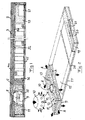
- the mattress includes an elastic bag-like covering 2 of textile being air-permeable, soft and wear resistant and surrounding the rest of the mattress for keeping the different parts thereof protected.
- the covering 2 may be opened to get access to the interior thereof through a zipper 30.
- a layer 3 of open foam is arranged under the top part of said covering 2.
- This layer is made of a soft and elastic material having an open structure with a good air-permeability both horizontally and vertically, such as reticulated polyurethane foam.
- An air-tight and elastic layer 4a is arranged under the layer 3 of open foam.
- the layer 4a is provided with through-holes 6 in a restricted region substantially corresponding to parts of upper support surfaces 7 of the mattress adapted to receive and support the trunk and the head of a person lying on the mattress.
- a further layer 5 with a good air-permeability is arranged under the layer 4a and functions as a channel layer.
- This layer 5 may have the properties as the layer 3 but is preferably slightly harder for not being obstructed by the pressure of a body resting on the mattress and the negative air pressure caused by a suction device disclosed further below.
- a further air-tight layer 4b is arranged under the layer 5 and this layer has an opening 8 at the foot end 9 of the mattress.
- a suction device in the form of a fan member 10 is arranged in a foam block 11 with a rather high density for good sound silencing properties with the suction side connected to said lower opening 8 of the air-tight layer 4b.
- the fan member 10 has circumferential exhaust openings 12 connected to two channels 13 arranged in said foam block 11 and having an extension including turns so as to suppress noises generated by the operation of the fan member 10.
- the channels 13 extend from the fan member 10 located centrally transversely with respect to the longitudinal direction of the mattress and end close to opposite lateral sides of the mattress for letting air out through lateral surfaces, bottom surfaces (air-permeable bottom plate 17) and end surfaces at the foot end of the mattress as shown through the arrows A in Figs 2 and 3 .
- a mid portion 15 of the mattress includes pocket springs 16 for supporting the upper parts of the mattress and making it comfortable for a person lying on the mattress.
- the mattress further comprises a foam block 19 of medium hardness at the head end 20 and having a cavity 21 opening laterally for receiving an arrangement 22 for regulating the power of the fan member 10, power means 23 and cabling 24 at least during transport of the mattress.
- the power means 23 includes preferably a transformer and rectifier for delivering a direct voltage of for instance 12V to said arrangement 22 controlling the power supplied to the fan member.
- the fan member may just as well be connected to a 12V battery would it be desired to use the mattress for instance onboard a boat.
- the fan member is preferably configured to run continuously either in a state of low power operation, for instance 2W, or a state of active operation at a power of for instance up to 15W.
- the mattress further comprises a first temperature sensor 25 configured to sense the temperature of the air sucked through the mattress and is here arranged inside the house of the fan member 10 on a circuit-card with a micro processor controlling the fan member, and a second temperature sensor 26 configured to sense the room temperature in the free space surrounding the mattress.
- the arrangement 22 may be configured to control the fan member 10 to change from said low power operation state to said active operation state when the temperature sensed by the first temperature sensor 25 exceeds the temperature sensed by the second temperature sensor by a predetermined value, such as 1°C, 2°C or 3°C.
- Said micro processor receives temperature information from the two sensors 25, 26 and is programmed to control the fan member to change to active operation state when the temperature difference sensed exceeds for instance 3°C and then change back to low power operation state when said difference falls below 3°C again.
- the arrangement is provided with means 27 allowing adjustment of a target temperature of the air sensed by said first temperature sensor once the suction device has changed from low power operation to active operation state. This target temperature may be well above the temperature at which said state change appears and thus be individually controlled by acting upon said means 27 according to the wishes of the person using the mattress.
- the state change will take place at a temperature of 24°C sensed by the first temperature sensor, and the fan member 10 may then be controlled towards a target temperature of for instance 30°C of the air reaching said first temperature sensor. Accordingly, the fan member will run at low power operation when no person is lying on the mattress and the temperature sensors will show the same temperature and then keep the upper support surfaces of the mattress dry and cool. When a person lies down on the mattress the temperature sensed by the first temperature sensor will increase and when it reaches a predetermined value the arrangement will switch the fan member to said active operation state.
- said target temperature is adjusted to be very low, for instance 25°C, whereas it may be adjusted to be 35°C if the person wishes to have a weak cooling effect.
- the arrangement may through said means 27 also be controlled to override any information from said temperature sensors in positions of a minimum and a maximum power supplied to the fan member obtained by hand control of a person using the mattress.
- the mattress of this embodiment may have a weight of 10 kg and a thickness of 9 cm and be rolled together into a roll with a diameter of approximately 45 cm, which may be carried along in a suitable bag 28 as schematically illustrated in Fig 4 .
- Said arrangement 22 may also be provided with a timer making it possible to the person to obtain a switching of the power supplied to the fan member to a lower power, for instance two hours before the person is expected to wake up, for slightly increasing the temperature sensed by the person when waking up.
- the mattress may also have a microphone 31 and an accelerometer 32 connected to the arrangement or adapted to communicate with a smart phone through a suitable app. This makes it possible also for hospitals to lend the mattress to people having sleeping problems so as to collect data during their sleep for analysis.
- the first temperature sensor may be supplemented by a moisture sensor sensing the moisture degree of the air sucked by the fan member and increasing the power of the fan member when the moisture degree of said air sucked through the fan member is abnormally high so as to reduce unpleasant experience of sweat from the body of a person resting on the mattress.
- a moisture sensor may be used for refining the regulation of the suction device.
- the air-permeable parts of the upper limitation of the mattress may as an alternative to said through-holes in the upper air-tight layer be achieved by having a more or less air-tight layer without such holes in a rest state but which opens up where a body of a person apply most pressure when lying on the mattress.
- the pocket springs in the mid portion may be replaced by a thicker, for instance 35 mm, foam layer having an open structure.
- the suction device of the mattress may have more than one fan member, and such fan members may be arranged in any conceivable way, such as in series or in parallel.
- the mattress comprises a suction device
- the mattress is provided with more than one fan member.
- Two fan members may for example be arranged in parallel or in series for increasing the power of the suction device. It would then also be possible to have one fan member for drawing air from an upper support surface of the mattress and one for blowing out air through an upper support surface of the mattress. These may then be controlled so that the one blowing is switched on when the one sucking does not manage to keep the temperature below a predetermined level. One of the fan members will then operate at the time.
Landscapes
- Mattresses And Other Support Structures For Chairs And Beds (AREA)
Priority Applications (1)
| Application Number | Priority Date | Filing Date | Title |
|---|---|---|---|
| PL15172536T PL2957191T3 (pl) | 2014-06-17 | 2015-06-17 | Materac wierzchni |
Applications Claiming Priority (1)
| Application Number | Priority Date | Filing Date | Title |
|---|---|---|---|
| SE1450752 | 2014-06-17 |
Publications (2)
| Publication Number | Publication Date |
|---|---|
| EP2957191A1 true EP2957191A1 (fr) | 2015-12-23 |
| EP2957191B1 EP2957191B1 (fr) | 2019-02-27 |
Family
ID=53442588
Family Applications (1)
| Application Number | Title | Priority Date | Filing Date |
|---|---|---|---|
| EP15172536.3A Active EP2957191B1 (fr) | 2014-06-17 | 2015-06-17 | Matelas superieur |
Country Status (3)
| Country | Link |
|---|---|
| EP (1) | EP2957191B1 (fr) |
| ES (1) | ES2726903T3 (fr) |
| PL (1) | PL2957191T3 (fr) |
Cited By (7)
| Publication number | Priority date | Publication date | Assignee | Title |
|---|---|---|---|---|
| EP3285618A4 (fr) * | 2015-04-23 | 2018-10-31 | Tempur-Pedic Management, LLC | Coussins de support et procédés d'aération active de ceux-ci |
| CN111166100A (zh) * | 2020-03-11 | 2020-05-19 | 江西蓝臻智能科技有限公司 | 一种多功能智能床垫 |
| USD919333S1 (en) | 2019-08-27 | 2021-05-18 | Casper Sleep Inc. | Mattress |
| USD927889S1 (en) | 2019-10-16 | 2021-08-17 | Casper Sleep Inc. | Mattress layer |
| US11116326B2 (en) | 2017-08-14 | 2021-09-14 | Casper Sleep Inc. | Mattress containing ergonomic and firmness-regulating endoskeleton |
| US11202517B2 (en) | 2014-04-21 | 2021-12-21 | Casper Sleep Inc. | Mattress |
| US11241100B2 (en) | 2018-04-23 | 2022-02-08 | Casper Sleep Inc. | Temperature-regulating mattress |
Citations (3)
| Publication number | Priority date | Publication date | Assignee | Title |
|---|---|---|---|---|
| US2493067A (en) | 1945-09-08 | 1950-01-03 | Louis J Goldsmith | Mattress |
| US20030019044A1 (en) * | 2000-03-09 | 2003-01-30 | Stefan Larsson | Bed |
| US20120233773A1 (en) * | 2008-09-21 | 2012-09-20 | Yoshio Suzuki | Ecological sleep bedding |
-
2015
- 2015-06-17 ES ES15172536T patent/ES2726903T3/es active Active
- 2015-06-17 PL PL15172536T patent/PL2957191T3/pl unknown
- 2015-06-17 EP EP15172536.3A patent/EP2957191B1/fr active Active
Patent Citations (3)
| Publication number | Priority date | Publication date | Assignee | Title |
|---|---|---|---|---|
| US2493067A (en) | 1945-09-08 | 1950-01-03 | Louis J Goldsmith | Mattress |
| US20030019044A1 (en) * | 2000-03-09 | 2003-01-30 | Stefan Larsson | Bed |
| US20120233773A1 (en) * | 2008-09-21 | 2012-09-20 | Yoshio Suzuki | Ecological sleep bedding |
Cited By (13)
| Publication number | Priority date | Publication date | Assignee | Title |
|---|---|---|---|---|
| US11202517B2 (en) | 2014-04-21 | 2021-12-21 | Casper Sleep Inc. | Mattress |
| US11622636B2 (en) | 2014-04-21 | 2023-04-11 | Casper Sleep Inc. | Mattress |
| EP3285618A4 (fr) * | 2015-04-23 | 2018-10-31 | Tempur-Pedic Management, LLC | Coussins de support et procédés d'aération active de ceux-ci |
| US11116326B2 (en) | 2017-08-14 | 2021-09-14 | Casper Sleep Inc. | Mattress containing ergonomic and firmness-regulating endoskeleton |
| US11241100B2 (en) | 2018-04-23 | 2022-02-08 | Casper Sleep Inc. | Temperature-regulating mattress |
| USD990935S1 (en) | 2019-08-27 | 2023-07-04 | Casper Sleep Inc. | Mattress |
| USD919333S1 (en) | 2019-08-27 | 2021-05-18 | Casper Sleep Inc. | Mattress |
| USD992932S1 (en) | 2019-08-27 | 2023-07-25 | Casper Sleep Inc. | Mattress |
| USD992933S1 (en) | 2019-08-27 | 2023-07-25 | Casper Sleep Inc. | Mattress |
| USD993673S1 (en) | 2019-08-27 | 2023-08-01 | Casper Sleep Inc. | Mattress |
| USD932809S1 (en) | 2019-10-16 | 2021-10-12 | Casper Sleep Inc. | Mattress layer |
| USD927889S1 (en) | 2019-10-16 | 2021-08-17 | Casper Sleep Inc. | Mattress layer |
| CN111166100A (zh) * | 2020-03-11 | 2020-05-19 | 江西蓝臻智能科技有限公司 | 一种多功能智能床垫 |
Also Published As
| Publication number | Publication date |
|---|---|
| PL2957191T3 (pl) | 2019-08-30 |
| EP2957191B1 (fr) | 2019-02-27 |
| ES2726903T3 (es) | 2019-10-10 |
Similar Documents
| Publication | Publication Date | Title |
|---|---|---|
| EP2957191A1 (fr) | Matelas superieur | |
| EP1261265B1 (fr) | Un lit | |
| KR102385587B1 (ko) | 열 회수 시스템을 갖는 주변 베딩 | |
| US8122540B2 (en) | Bed headboard with ventilation system | |
| AU2001237887A1 (en) | A bed | |
| US6425527B1 (en) | Temperature control device for sleeping | |
| US7913332B1 (en) | Drawn air bed ventilator | |
| US11389006B2 (en) | Air-conditioned mattress topper | |
| KR101393469B1 (ko) | 통풍건조가 용이한 침대 매트리스 | |
| US12137810B2 (en) | Bedding system, kit and method | |
| CN213046266U (zh) | 一种具有透气通风功能的床垫 | |
| KR101886245B1 (ko) | 침대 | |
| KR100826793B1 (ko) | 열전달편이 배열된 냉온풍 침대 | |
| TWM608590U (zh) | 透氣溫控床墊機構 | |
| AU2024227479B2 (en) | Bedding System, Kit and Method | |
| WO2005034690A1 (fr) | Coussin permettant d'ameliorer la sante | |
| US20250000271A1 (en) | Devices and Systems to Control Bed Temperature and Moisture Level | |
| WO2010016759A2 (fr) | Dispositif pour fournir un flux d'air à un lit, et lit équipé de ce dispositif |
Legal Events
| Date | Code | Title | Description |
|---|---|---|---|
| PUAI | Public reference made under article 153(3) epc to a published international application that has entered the european phase |
Free format text: ORIGINAL CODE: 0009012 |
|
| AK | Designated contracting states |
Kind code of ref document: A1 Designated state(s): AL AT BE BG CH CY CZ DE DK EE ES FI FR GB GR HR HU IE IS IT LI LT LU LV MC MK MT NL NO PL PT RO RS SE SI SK SM TR |
|
| AX | Request for extension of the european patent |
Extension state: BA ME |
|
| 17P | Request for examination filed |
Effective date: 20160615 |
|
| RBV | Designated contracting states (corrected) |
Designated state(s): AL AT BE BG CH CY CZ DE DK EE ES FI FR GB GR HR HU IE IS IT LI LT LU LV MC MK MT NL NO PL PT RO RS SE SI SK SM TR |
|
| GRAP | Despatch of communication of intention to grant a patent |
Free format text: ORIGINAL CODE: EPIDOSNIGR1 |
|
| STAA | Information on the status of an ep patent application or granted ep patent |
Free format text: STATUS: GRANT OF PATENT IS INTENDED |
|
| INTG | Intention to grant announced |
Effective date: 20180913 |
|
| GRAS | Grant fee paid |
Free format text: ORIGINAL CODE: EPIDOSNIGR3 |
|
| GRAA | (expected) grant |
Free format text: ORIGINAL CODE: 0009210 |
|
| STAA | Information on the status of an ep patent application or granted ep patent |
Free format text: STATUS: THE PATENT HAS BEEN GRANTED |
|
| AK | Designated contracting states |
Kind code of ref document: B1 Designated state(s): AL AT BE BG CH CY CZ DE DK EE ES FI FR GB GR HR HU IE IS IT LI LT LU LV MC MK MT NL NO PL PT RO RS SE SI SK SM TR |
|
| REG | Reference to a national code |
Ref country code: GB Ref legal event code: FG4D |
|
| REG | Reference to a national code |
Ref country code: CH Ref legal event code: EP |
|
| REG | Reference to a national code |
Ref country code: AT Ref legal event code: REF Ref document number: 1100124 Country of ref document: AT Kind code of ref document: T Effective date: 20190315 |
|
| REG | Reference to a national code |
Ref country code: IE Ref legal event code: FG4D |
|
| REG | Reference to a national code |
Ref country code: DE Ref legal event code: R096 Ref document number: 602015025216 Country of ref document: DE |
|
| REG | Reference to a national code |
Ref country code: NL Ref legal event code: FP |
|
| REG | Reference to a national code |
Ref country code: SE Ref legal event code: TRGR |
|
| REG | Reference to a national code |
Ref country code: LT Ref legal event code: MG4D |
|
| PG25 | Lapsed in a contracting state [announced via postgrant information from national office to epo] |
Ref country code: NO Free format text: LAPSE BECAUSE OF FAILURE TO SUBMIT A TRANSLATION OF THE DESCRIPTION OR TO PAY THE FEE WITHIN THE PRESCRIBED TIME-LIMIT Effective date: 20190527 Ref country code: LT Free format text: LAPSE BECAUSE OF FAILURE TO SUBMIT A TRANSLATION OF THE DESCRIPTION OR TO PAY THE FEE WITHIN THE PRESCRIBED TIME-LIMIT Effective date: 20190227 Ref country code: FI Free format text: LAPSE BECAUSE OF FAILURE TO SUBMIT A TRANSLATION OF THE DESCRIPTION OR TO PAY THE FEE WITHIN THE PRESCRIBED TIME-LIMIT Effective date: 20190227 Ref country code: PT Free format text: LAPSE BECAUSE OF FAILURE TO SUBMIT A TRANSLATION OF THE DESCRIPTION OR TO PAY THE FEE WITHIN THE PRESCRIBED TIME-LIMIT Effective date: 20190627 |
|
| PG25 | Lapsed in a contracting state [announced via postgrant information from national office to epo] |
Ref country code: RS Free format text: LAPSE BECAUSE OF FAILURE TO SUBMIT A TRANSLATION OF THE DESCRIPTION OR TO PAY THE FEE WITHIN THE PRESCRIBED TIME-LIMIT Effective date: 20190227 Ref country code: BG Free format text: LAPSE BECAUSE OF FAILURE TO SUBMIT A TRANSLATION OF THE DESCRIPTION OR TO PAY THE FEE WITHIN THE PRESCRIBED TIME-LIMIT Effective date: 20190527 Ref country code: HR Free format text: LAPSE BECAUSE OF FAILURE TO SUBMIT A TRANSLATION OF THE DESCRIPTION OR TO PAY THE FEE WITHIN THE PRESCRIBED TIME-LIMIT Effective date: 20190227 Ref country code: IS Free format text: LAPSE BECAUSE OF FAILURE TO SUBMIT A TRANSLATION OF THE DESCRIPTION OR TO PAY THE FEE WITHIN THE PRESCRIBED TIME-LIMIT Effective date: 20190627 Ref country code: LV Free format text: LAPSE BECAUSE OF FAILURE TO SUBMIT A TRANSLATION OF THE DESCRIPTION OR TO PAY THE FEE WITHIN THE PRESCRIBED TIME-LIMIT Effective date: 20190227 Ref country code: GR Free format text: LAPSE BECAUSE OF FAILURE TO SUBMIT A TRANSLATION OF THE DESCRIPTION OR TO PAY THE FEE WITHIN THE PRESCRIBED TIME-LIMIT Effective date: 20190528 |
|
| REG | Reference to a national code |
Ref country code: AT Ref legal event code: MK05 Ref document number: 1100124 Country of ref document: AT Kind code of ref document: T Effective date: 20190227 |
|
| REG | Reference to a national code |
Ref country code: ES Ref legal event code: FG2A Ref document number: 2726903 Country of ref document: ES Kind code of ref document: T3 Effective date: 20191010 |
|
| PG25 | Lapsed in a contracting state [announced via postgrant information from national office to epo] |
Ref country code: EE Free format text: LAPSE BECAUSE OF FAILURE TO SUBMIT A TRANSLATION OF THE DESCRIPTION OR TO PAY THE FEE WITHIN THE PRESCRIBED TIME-LIMIT Effective date: 20190227 Ref country code: AL Free format text: LAPSE BECAUSE OF FAILURE TO SUBMIT A TRANSLATION OF THE DESCRIPTION OR TO PAY THE FEE WITHIN THE PRESCRIBED TIME-LIMIT Effective date: 20190227 Ref country code: DK Free format text: LAPSE BECAUSE OF FAILURE TO SUBMIT A TRANSLATION OF THE DESCRIPTION OR TO PAY THE FEE WITHIN THE PRESCRIBED TIME-LIMIT Effective date: 20190227 Ref country code: SK Free format text: LAPSE BECAUSE OF FAILURE TO SUBMIT A TRANSLATION OF THE DESCRIPTION OR TO PAY THE FEE WITHIN THE PRESCRIBED TIME-LIMIT Effective date: 20190227 Ref country code: RO Free format text: LAPSE BECAUSE OF FAILURE TO SUBMIT A TRANSLATION OF THE DESCRIPTION OR TO PAY THE FEE WITHIN THE PRESCRIBED TIME-LIMIT Effective date: 20190227 Ref country code: CZ Free format text: LAPSE BECAUSE OF FAILURE TO SUBMIT A TRANSLATION OF THE DESCRIPTION OR TO PAY THE FEE WITHIN THE PRESCRIBED TIME-LIMIT Effective date: 20190227 |
|
| REG | Reference to a national code |
Ref country code: DE Ref legal event code: R097 Ref document number: 602015025216 Country of ref document: DE |
|
| PG25 | Lapsed in a contracting state [announced via postgrant information from national office to epo] |
Ref country code: SM Free format text: LAPSE BECAUSE OF FAILURE TO SUBMIT A TRANSLATION OF THE DESCRIPTION OR TO PAY THE FEE WITHIN THE PRESCRIBED TIME-LIMIT Effective date: 20190227 |
|
| PG25 | Lapsed in a contracting state [announced via postgrant information from national office to epo] |
Ref country code: AT Free format text: LAPSE BECAUSE OF FAILURE TO SUBMIT A TRANSLATION OF THE DESCRIPTION OR TO PAY THE FEE WITHIN THE PRESCRIBED TIME-LIMIT Effective date: 20190227 |
|
| PLBE | No opposition filed within time limit |
Free format text: ORIGINAL CODE: 0009261 |
|
| STAA | Information on the status of an ep patent application or granted ep patent |
Free format text: STATUS: NO OPPOSITION FILED WITHIN TIME LIMIT |
|
| PG25 | Lapsed in a contracting state [announced via postgrant information from national office to epo] |
Ref country code: MC Free format text: LAPSE BECAUSE OF FAILURE TO SUBMIT A TRANSLATION OF THE DESCRIPTION OR TO PAY THE FEE WITHIN THE PRESCRIBED TIME-LIMIT Effective date: 20190227 |
|
| REG | Reference to a national code |
Ref country code: CH Ref legal event code: PL |
|
| 26N | No opposition filed |
Effective date: 20191128 |
|
| PG25 | Lapsed in a contracting state [announced via postgrant information from national office to epo] |
Ref country code: SI Free format text: LAPSE BECAUSE OF FAILURE TO SUBMIT A TRANSLATION OF THE DESCRIPTION OR TO PAY THE FEE WITHIN THE PRESCRIBED TIME-LIMIT Effective date: 20190227 |
|
| PG25 | Lapsed in a contracting state [announced via postgrant information from national office to epo] |
Ref country code: TR Free format text: LAPSE BECAUSE OF FAILURE TO SUBMIT A TRANSLATION OF THE DESCRIPTION OR TO PAY THE FEE WITHIN THE PRESCRIBED TIME-LIMIT Effective date: 20190227 |
|
| PG25 | Lapsed in a contracting state [announced via postgrant information from national office to epo] |
Ref country code: IE Free format text: LAPSE BECAUSE OF NON-PAYMENT OF DUE FEES Effective date: 20190617 |
|
| PG25 | Lapsed in a contracting state [announced via postgrant information from national office to epo] |
Ref country code: LI Free format text: LAPSE BECAUSE OF NON-PAYMENT OF DUE FEES Effective date: 20190630 Ref country code: LU Free format text: LAPSE BECAUSE OF NON-PAYMENT OF DUE FEES Effective date: 20190617 Ref country code: CH Free format text: LAPSE BECAUSE OF NON-PAYMENT OF DUE FEES Effective date: 20190630 |
|
| PG25 | Lapsed in a contracting state [announced via postgrant information from national office to epo] |
Ref country code: CY Free format text: LAPSE BECAUSE OF FAILURE TO SUBMIT A TRANSLATION OF THE DESCRIPTION OR TO PAY THE FEE WITHIN THE PRESCRIBED TIME-LIMIT Effective date: 20190227 |
|
| PG25 | Lapsed in a contracting state [announced via postgrant information from national office to epo] |
Ref country code: MT Free format text: LAPSE BECAUSE OF FAILURE TO SUBMIT A TRANSLATION OF THE DESCRIPTION OR TO PAY THE FEE WITHIN THE PRESCRIBED TIME-LIMIT Effective date: 20190227 Ref country code: HU Free format text: LAPSE BECAUSE OF FAILURE TO SUBMIT A TRANSLATION OF THE DESCRIPTION OR TO PAY THE FEE WITHIN THE PRESCRIBED TIME-LIMIT; INVALID AB INITIO Effective date: 20150617 |
|
| PG25 | Lapsed in a contracting state [announced via postgrant information from national office to epo] |
Ref country code: MK Free format text: LAPSE BECAUSE OF FAILURE TO SUBMIT A TRANSLATION OF THE DESCRIPTION OR TO PAY THE FEE WITHIN THE PRESCRIBED TIME-LIMIT Effective date: 20190227 |
|
| P01 | Opt-out of the competence of the unified patent court (upc) registered |
Effective date: 20230520 |
|
| PGFP | Annual fee paid to national office [announced via postgrant information from national office to epo] |
Ref country code: GB Payment date: 20240618 Year of fee payment: 10 |
|
| PGFP | Annual fee paid to national office [announced via postgrant information from national office to epo] |
Ref country code: DE Payment date: 20250624 Year of fee payment: 11 |
|
| PGFP | Annual fee paid to national office [announced via postgrant information from national office to epo] |
Ref country code: NL Payment date: 20250624 Year of fee payment: 11 |
|
| PGFP | Annual fee paid to national office [announced via postgrant information from national office to epo] |
Ref country code: FR Payment date: 20250629 Year of fee payment: 11 |
|
| PGFP | Annual fee paid to national office [announced via postgrant information from national office to epo] |
Ref country code: SE Payment date: 20250625 Year of fee payment: 11 |
|
| PGFP | Annual fee paid to national office [announced via postgrant information from national office to epo] |
Ref country code: ES Payment date: 20250702 Year of fee payment: 11 |
|
| PGFP | Annual fee paid to national office [announced via postgrant information from national office to epo] |
Ref country code: IT Payment date: 20250624 Year of fee payment: 11 Ref country code: PL Payment date: 20250613 Year of fee payment: 11 |
|
| PGFP | Annual fee paid to national office [announced via postgrant information from national office to epo] |
Ref country code: BE Payment date: 20250625 Year of fee payment: 11 |