EP2957253A1 - Dispositif lingual orthodontique - Google Patents
Dispositif lingual orthodontique Download PDFInfo
- Publication number
- EP2957253A1 EP2957253A1 EP14382242.7A EP14382242A EP2957253A1 EP 2957253 A1 EP2957253 A1 EP 2957253A1 EP 14382242 A EP14382242 A EP 14382242A EP 2957253 A1 EP2957253 A1 EP 2957253A1
- Authority
- EP
- European Patent Office
- Prior art keywords
- mesial
- molar
- distal
- central arm
- premolar
- Prior art date
- Legal status (The legal status is an assumption and is not a legal conclusion. Google has not performed a legal analysis and makes no representation as to the accuracy of the status listed.)
- Granted
Links
Images





Classifications
-
- A—HUMAN NECESSITIES
- A61—MEDICAL OR VETERINARY SCIENCE; HYGIENE
- A61C—DENTISTRY; APPARATUS OR METHODS FOR ORAL OR DENTAL HYGIENE
- A61C7/00—Orthodontics, i.e. obtaining or maintaining the desired position of teeth, e.g. by straightening, evening, regulating, separating, or by correcting malocclusions
- A61C7/12—Brackets; Arch wires; Combinations thereof; Accessories therefor
- A61C7/14—Brackets; Fixing brackets to teeth
- A61C7/145—Lingual brackets
-
- A—HUMAN NECESSITIES
- A61—MEDICAL OR VETERINARY SCIENCE; HYGIENE
- A61C—DENTISTRY; APPARATUS OR METHODS FOR ORAL OR DENTAL HYGIENE
- A61C7/00—Orthodontics, i.e. obtaining or maintaining the desired position of teeth, e.g. by straightening, evening, regulating, separating, or by correcting malocclusions
-
- A—HUMAN NECESSITIES
- A61—MEDICAL OR VETERINARY SCIENCE; HYGIENE
- A61C—DENTISTRY; APPARATUS OR METHODS FOR ORAL OR DENTAL HYGIENE
- A61C7/00—Orthodontics, i.e. obtaining or maintaining the desired position of teeth, e.g. by straightening, evening, regulating, separating, or by correcting malocclusions
- A61C7/12—Brackets; Arch wires; Combinations thereof; Accessories therefor
-
- A—HUMAN NECESSITIES
- A61—MEDICAL OR VETERINARY SCIENCE; HYGIENE
- A61C—DENTISTRY; APPARATUS OR METHODS FOR ORAL OR DENTAL HYGIENE
- A61C7/00—Orthodontics, i.e. obtaining or maintaining the desired position of teeth, e.g. by straightening, evening, regulating, separating, or by correcting malocclusions
- A61C7/12—Brackets; Arch wires; Combinations thereof; Accessories therefor
- A61C7/14—Brackets; Fixing brackets to teeth
-
- A—HUMAN NECESSITIES
- A61—MEDICAL OR VETERINARY SCIENCE; HYGIENE
- A61C—DENTISTRY; APPARATUS OR METHODS FOR ORAL OR DENTAL HYGIENE
- A61C7/00—Orthodontics, i.e. obtaining or maintaining the desired position of teeth, e.g. by straightening, evening, regulating, separating, or by correcting malocclusions
- A61C7/12—Brackets; Arch wires; Combinations thereof; Accessories therefor
- A61C7/20—Arch wires
- A61C7/22—Tension adjusting means
-
- A—HUMAN NECESSITIES
- A61—MEDICAL OR VETERINARY SCIENCE; HYGIENE
- A61C—DENTISTRY; APPARATUS OR METHODS FOR ORAL OR DENTAL HYGIENE
- A61C7/00—Orthodontics, i.e. obtaining or maintaining the desired position of teeth, e.g. by straightening, evening, regulating, separating, or by correcting malocclusions
- A61C7/36—Devices acting between upper and lower teeth
Definitions
- the present disclosure relates to an orthodontic device, and more particularly relates to an orthodontic lingual device for segmental distalization.
- the present disclosure further relates to methods for mounting and using orthodontic devices.
- an orthodontic bracket fitted to the upper molar brace is provided with a head gear tube.
- the head gear wire is inserted into the head gear tube and tensile forces are exerted on the head gear wire by a strap extending behind a patient's neck.
- a distalizing element is known from e.g. EP1649824 .
- This document relates to an auxiliary element for the segmental distalization of the canine-to-molar posterior maxillary area in orthodontic treatments. Many of the aforementioned problems are at least partially resolved by such a distalizing element.
- an orthodontic device for segmental distalization in a patient includes an elongated central arm; a distal part comprising a distal base surface adapted to be attached to a lingual surface of a molar, wherein the distal part is located at a distal end of the elongated central arm.
- the device also includes a mesial part comprising a mesial base surface adapted to be attached to a lingual surface of a premolar, wherein the mesial part is located at a mesial end of the elongated central arm.
- the mesial part and/or the distal part comprises a first retention element for retention of a first end of an actuating element.
- the elongated central arm is shaped to substantially follow a lingual side of a set of teeth between the molar and the premolar of the patient.
- the mesial part may comprise a first hooking element for retention of a first end of an elastic element e.g. a rubber band that may be suspended around the hook. Consequently, a force pulling the premolar backwards (mesial-distal direction) may be provided.
- the distal part may comprise a first retention element e.g. a pocket for receiving a first end of an (elastic) piston. In this case, the distal part can be pushed backwards.
- a molar may be pushed or pulled backwards.
- the central arm (or "central bar") connects the distal part of the device to the mesial part.
- a rotational force in a pivot about the root(s) of a molar may be provided.
- a rotation in the distal direction of a molar (“uprighting") may be achieved.
- the rotational force pivoting the molar around its root(s) could be expected to have a negative effect on the position of the molar in that the rotation of the molar is contrary to the desired result. It has however been found that due to the fact that the distalization is segmental (i.e. involves a block of teeth) and due to the point of contact between the teeth, the teeth located mesial of the molar bring about a moment that compensates the undesired moment brought about by the attachment of the device on the lingual side of the molar.
- the orthodontic device according to this aspect is adapted to be attached to a premolar instead of a canine.
- the number of teeth to be displaced is thus smaller than in such a prior art device.
- the elongated central arm may thus be shorter and straighter, which can result in an improved efficiency of device. As less transceptal fibres of periodontal tissue are included, the efficiency may be improved.
- an orthodontic device may be mounted onto the lingual surfaces of a molar and a premolar.
- the orthodontic device may be aesthetically pleasant, by ensuring that the orthodontic device is hardly observable in the mouth
- a distalizing element on a lingual side of the teeth furthermore provides additional and/or improved anchoring methods as compared to the prior art.
- the palate, and in particular the hard palate provides a relatively large area for implanting anchors such as TAD's, mini-implants or mini-screws (bone anchorage). Anchors in the hard palate do not interfere with roots of teeth while the teeth themselves may be subject to moving as a result of the treatment.
- the provision of the device on the lingual side thus enables and enhances intra-maxillary traction (pushing or pulling between anchor and orthodontic device) instead of inter-maxillary traction.
- the elongated central arm of the orthodontic device may be adapted e.g. curved in order to follow the lingual side of different sets of teeth e.g. between a molar and a premolar of the patient.
- the central arm thus does not have to interfere with the tongue.
- the central arm may be slightly concave when seen from the inside of the mouth.
- the orthodontic device may thus be used in different parts of the mouth e.g. the left quadrant of the mandible, the right quadrant of the mandible, the left quadrant of the maxilla, the right quadrant of the maxilla, thus the flexibility and the usability of the device may be improved as compared to prior art devices.
- the orthodontic device may be adapted to be fitted between a first premolar, and a first molar, or a second molar or a third molar ("wisdom tooth").
- the orthodontic device can also be adapted to fit between a second premolar, and a first molar, or a second molar or a third molar.
- a trained professional may choose from these options in accordance with a patient's malocclusion.
- the distal part of the elongated central arm may be provided with flexibility such that an angle between the distal part of the elongated central arm and a neighbouring portion of the elongated central arm can be adapted.
- the orthodontic device may be elastically deformed in the distal part; due to this pre-deformation the orthodontic device may be installed with an initial tension, thus an extra force may be exerted on a molar in a lingual direction ("inwards").
- This can provide for a counterclockwise rotation of a molar in a right quadrant (when seen from above) or a clockwise rotation of a molar in a left quadrant. This rotation is generally desirable in many patients to fully correct their malocclusions.
- a kit further comprising an anchor including a second retention element for retention of a second end of the actuating element.
- a patient may be provided with an anchor device e.g. a splint, a bracket, an implant (or another anchor device) that may act as a solid fixation device to retain the another end of the actuating element.
- a method for mounting a device substantially as hereinbefore described includes elastically deforming a distal end region of the central elongated arm, and mounting said at least one end to a tooth, such that the device is pre-stressed when mounted.
- a method for treating a malocclusion in a patient may comprise mounting a lingual orthodontic device substantially as hereinbefore described on a premolar and a molar.
- the method may furthermore comprise attaching an actuating element to a retention element on the lingual orthodontic device.
- the method may furthermore comprise monitoring the movement of a set of teeth of the mandible with respect to the maxilla (or the other way round) and removing the orthodontic device when the mandibular teeth and maxillary teeth in a posterior section of the mouth are aligned. Subsequently, brackets may be provided.
- the backwards force provided during treatment of the malocclusion may be varied by e.g. changing the stiffness of the actuating element.
- the actuating element is a rubber band
- throughout the treatment such a rubber band can be substituted by another rubber band of different stiffness and elasticity.
- such a method for treatment may comprise elastically deforming a distal portion of the orthodontic device and monitoring the orientation of the molar.
- the inwards force applied by the distal portion to the molar may be varied throughout the treatment.
- Figure 1 illustrates the configuration of the teeth in the mandible (lower jaw bone).
- a rear part of the mouth 120 may be referred to as a distal part of the mouth.
- a front part of the mouth 110 may be referred to as a mesial part of the mouth.
- An inner portion of the mouth behind the teeth 130 may be referred to as a lingual region.
- An outer portion of the mouth 140 may be referred to as a labial region.
- a mesial-distal direction 115 with respect to a specific tooth has been schematically indicated in figure 1 .
- the lingual-labial direction 135 may be indicated with respect to the same tooth.
- the third molars (wisdom molars) have been included.
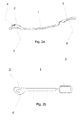
- Figures 2a and 2b illustrate an orthodontic device that may be adapted for the segmental distalization of a premolar and a molar.
- An elongated central bar (or "arm") 1 may be integrally formed with a distal part 3 that may include a distal base surface 6 adapted to be attached to a lingual surface of a molar (not shown in this figure).
- the elongated central arm 1 may also be integrally formed with a mesial part 2 comprising a mesial base surface 5 adapted to be attached to a lingual surface of a premolar (not shown).
- the elongated central bar, the distal part and the mesial part may thus form a monolithic element.
- the base surfaces of both the distal part and the mesial part may comprise a shape suitable for retention. Although in the illustrated example a plurality of protuberances may be shown, other alternatives may be used.
- the base surfaces may be mounted on the teeth using e.g. adhesive dental cement.
- the elongated central arm 1 may be substantially shaped following the lingual side of a plurality of teeth between the molar and the premolar of a patient.
- the central arm 1 may be slightly concave as shown in figure 2a .
- a hooking element 4 may be located on the outer part of the mesial part 2.
- the hooking element 4 may be made of the same material and may be integrally formed with the mesial part 2.
- the hooking element 4 may however have any suitable shape and be made of any suitable material as long as an actuating element can be retained.
- An elastic element e.g. a rubber band may be strung around the hooking element 4 and the elastic element may provide a mesial-distal force (backwards) in the premolar.
- a second end of such an elastic element may be attached to e.g. a hook on a bracket or an implant. The elastic element can thus actuate on the orthodontic device and provide a force in a distal direction.
- a molar (not shown in this figure) may be pushed backwards.
- a set of teeth including the premolar and the molar and the teeth in between may thus be repositioned as a group.
- a rotation in the distal direction of a molar (“uprighting") may be achieved.
- the hooking element in figure 2b may be seen to extend forwards (i.e. in a mesial direction).
- the hooking element may extend forwards in a substantially straight manner and may be provided in a substantially central portion of the mesial part.
- the symmetric shape of the resulting orthodontic device makes it possible for a single device to be fitted both in a right and a left quadrant of a patient's mouth.
- the hooking element may in alternative examples also extend slightly upwards for improved retention.
- the hooking element may be in the form of a round or substantially mushroom-shaped button around which an elastic band can be fitted.
- the orthodontic device may be made from any suitable material including e.g. metals (alloys) or polymer: the polymers may be fibre-reinforced or not.
- the orthodontic device may also be manufactured with materials that can include translucent or transparent material, and thus the aesthetic aspects may be improved.
- the orthodontic device may be manufactured in different ways. This device may be moulded. When it is made from metals, they may also be made by machining.
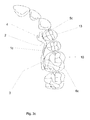
- Figure 3a illustrates an orthodontic device adapted for the segmental distalization of the first premolar 12 and a second molar 11 located in the left quadrant of the mandible (lower jaw bone).
- the tooth 11 may be regarded to as the mandibular second molar 11. Further indicated are the first molar 9, the second premolar 81, the first premolar 12, a canine 82, and incisors 83 and 84.
- the distal base surface 6a of the device may be attached to a lingual surface of the second molar 11.
- the mesial base surface 5a may be attached to a lingual surface of the first premolar 12.
- the elongated central arm 1a may be substantially shaped to follow the lingual side of a second premolar and a first molar between the second molar and the first premolar both located in the mandible (lower jaw bone).
- the attachment of the distal base surface 6a and/or the attachment of the mesial base surface 5a may be performed by means of a material suitable for retention e.g. adhesive dental cement; the adhesive dental cement may be placed onto the distal base surface 6a and/or the mesial base surface 5a.
- the mesial base surface 5a may be placed in a precise position onto the first premolar and/or the distal base surface 6a may be placed in a precise position onto the second molar, the excess of adhesive dental cement may be removed, thus the distal base surface 6a and the mesial base 5a surface may be fixed.
- Some other elements for the attachment may also be possible.
- the dimensions of the device are such that practitioners only have to fit the device in a position where they would usually mount a bracket. This can make the device particularly easy to use for practitioners and may lead to higher acceptance in the dental community.
- the exact position of the base surface with respect to a tooth may depend on a specific malocclusion and may thus be varied.
- a professional may intentionally choose e.g. a relative forward portion of a molar for the attachment of the orthodontic device. If a (pushing) force is provided in a diagonal direction (i.e. having both a component in a rearward direction and a component substantially sideways and thus perpendicular to the rearward direction), then a suitable rotational moment may be provided to the molar to add a rotation around its roots.
- actuating element such as e.g a rubber band
- another retention element at a second end of the actuating element
- a backwards force is provided to the set of teeth involving, the first and second premolars and the first and second molars.
- the whole block of teeth may thus be moved backwards.
- the second retention element may e.g. be a hook on an implant or on a lingual bracket.
- a bracket comprising such a hook may be mounted on a maxillary molar, e.g. a maxillary first molar.
- a maxillary ferrule may ensure that the maxillary teeth do not move forward under the influence of the reaction force acting of the bracket.
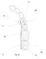
- Figure 3b illustrates an orthodontic device adapted for the segmental distalization of the first premolar 12 and a first molar 9 located in the left quadrant of the mandible (lower jaw bone).
- same reference numbers denote the same elements as those in the figure 2a .
- the distal base surface 6b may be attached to the lingual surface of the first molar 9.
- the mesial base surface 5b may be attached to the lingual surface of the first premolar 12.
- the elongated central arm 1 b may be substantially shaped following the lingual side of a second premolar between the first molar 9 and the first premolar 12 both located in the mandible (lower jaw bone).
- the attachment of the distal base surface 6b and/or the attachment of the mesial base surface 5b may be performed in substantially the same way as described in figure 2a .
- the central arm 1 b may be curved outwards (in the labial direction) following the gap between the second premolar 81 and the first molar 9 at the lingual side and inwards (in the lingual direction) near the distal base surface 6b.
- FIGS. 3c and 3d show similar examples for maxillary distalization.
- the distalization device may be attached to either a first or second molar.
- same references numbers denote the same elements as those in the figure 2a .
- An implant with a retention element may be provided in the patient's palate.
- a rubber band or other elastic element may be connected between such an implant and the hooking element 4.
- a bracket mounted on a lingual surface of a mandibular tooth may serve for the necessary retention and backwards traction.
- a bracket may be mounted on a mandibular molar, in particular a first molar.
- a ferrule may be provided for the mandibular so that the mandibular teeth do not move forward.
- Figure 3e shows further similar examples for maxillary distalization.
- an orthodontic device adapted for the segmental distalization of the second premolar 60 and a second molar 11 located in the left quadrant of the mandible (lower jaw bone) may be provided.
- same references numbers denote the same elements as those in the figure 2a .
- the distalizing device may connect a premolar to a third molar ("wisdom tooth").
- the figure 3f illustrates an orthodontic device adapted for the segmental distalization of the first premolar 12 and a first molar 9 located in the left quadrant of the maxilla (upper jaw bone).
- the distal base surface 6f may be attached to a lingual surface of the second molar 9.
- the mesial base surface 5f may be attached to a lingual surface of the first premolar 12.
- the elongated central arm 1f may be substantially shaped following the lingual side of a first premolar 12 and a first molar 9 both located in the mandible (lower jaw bone).
- the attachment of the distal base surface 6f and/or the attachment of the mesial base surface 5f may be performed in a similar way as described in figure 3a .
- a retention element 72 may be provided on the distal part 3 of the elongated central arm 1.
- the retention element 72 may be made of the same material and integrally formed with the distal part 3.
- the retention element may be in the shape of a pocket receiving a first end of the actuating element 71.
- the actuating element 71 may be a resilient element 71 such as e.g. a spring
- the resilient element 71 may be made of metal but other materials are also possible,
- An implant pin 70 may be attached in the palate.
- the mesial end of the resilient element 71 may be attached to the pin connection 70.
- the actuating element pushing backwards against the molar may comprise a spring actuated piston.
- the resilient element may provide a force in the distal part 3 of the distalizer backwards (mesial-distal direction) and therefore, extra rearwards force in the first molar 9 may be provided.
- a pulling arrangement involving e.g. a hooking element with an elastic band
- a pushing arrangement involving e.g. a receptacle on a distal part.
- a base surface of the distal part of the orthodontic device may be mounted in a relatively forward position on the molar. If a (pushing) force is provided in a more diagonal direction, then the component of the force in the sideways (lingual-labial) direction may establish a rotational moment to the molar to aid in a rotation around its roots.
- the amount of space available for the teeth may be increased. In many treatments, this is an alternative to tooth extraction.
- Figure 4 illustrates another example of an orthodontic device adapted for the segmental distalization.
- the distal part 3 of the elongated central arm 1 may be elastically deformable such that an angle between the distal part 3 and the elongated central arm 1 may be adapted.
- the flexibility may be provided by a distal end region of the central arm being thinner than other portions of the central arm.
- the distal part may thus have a relatively wide range of movement with respect to the central arm.
- the angle a between the longitudinal axis of the elongated central arm and the base surface may be between 90° and 30°, and in particular between 75° and 45°.
- the orthodontic device may be elastically deformed in the distal part. Due to this deformation the orthodontic device may be installed with an initial tension, and thus an extra force may be exerted on a molar.
- such flexibility could also be provided for the mesial part. Elastic deformation of the mesial portion may thus achieve additional inwards force to the first premolar (not shown) in a lingual direction.
- both the mesial part and the distal part may have sufficient flexibility and may be elastically deformed before mounting.
Landscapes
- Health & Medical Sciences (AREA)
- Oral & Maxillofacial Surgery (AREA)
- Dentistry (AREA)
- Epidemiology (AREA)
- Life Sciences & Earth Sciences (AREA)
- Animal Behavior & Ethology (AREA)
- General Health & Medical Sciences (AREA)
- Public Health (AREA)
- Veterinary Medicine (AREA)
- Dental Tools And Instruments Or Auxiliary Dental Instruments (AREA)
Priority Applications (4)
| Application Number | Priority Date | Filing Date | Title |
|---|---|---|---|
| EP14382242.7A EP2957253B1 (fr) | 2014-06-20 | 2014-06-20 | Dispositif lingual orthodontique |
| ES14382242T ES2858561T3 (es) | 2014-06-20 | 2014-06-20 | Dispositivo lingual de ortodoncia |
| US14/743,323 US9649176B2 (en) | 2014-06-20 | 2015-06-18 | Orthodontic lingual device |
| US15/482,484 US9987104B2 (en) | 2014-06-20 | 2017-04-07 | Orthodontic lingual device |
Applications Claiming Priority (1)
| Application Number | Priority Date | Filing Date | Title |
|---|---|---|---|
| EP14382242.7A EP2957253B1 (fr) | 2014-06-20 | 2014-06-20 | Dispositif lingual orthodontique |
Publications (2)
| Publication Number | Publication Date |
|---|---|
| EP2957253A1 true EP2957253A1 (fr) | 2015-12-23 |
| EP2957253B1 EP2957253B1 (fr) | 2020-12-09 |
Family
ID=51167830
Family Applications (1)
| Application Number | Title | Priority Date | Filing Date |
|---|---|---|---|
| EP14382242.7A Active EP2957253B1 (fr) | 2014-06-20 | 2014-06-20 | Dispositif lingual orthodontique |
Country Status (3)
| Country | Link |
|---|---|
| US (2) | US9649176B2 (fr) |
| EP (1) | EP2957253B1 (fr) |
| ES (1) | ES2858561T3 (fr) |
Cited By (3)
| Publication number | Priority date | Publication date | Assignee | Title |
|---|---|---|---|---|
| CN109745130A (zh) * | 2019-02-20 | 2019-05-14 | 重庆医科大学附属口腔医院 | 一种下颌后牙压低装置 |
| US20220202534A1 (en) * | 2020-12-29 | 2022-06-30 | Mark A. Payne | Distalizer and method of assembly |
| US11413118B2 (en) * | 2017-06-28 | 2022-08-16 | Spartan Orthodontics, Inc. | Orthodontic molar distalizer |
Families Citing this family (3)
| Publication number | Priority date | Publication date | Assignee | Title |
|---|---|---|---|---|
| EP3409235A1 (fr) * | 2017-05-29 | 2018-12-05 | Orthodontic Research and Development, S.L. | Dispositif orthodontique |
| US11654000B2 (en) | 2018-11-09 | 2023-05-23 | Under Dog Media, L.P. | Anteroposterior correction devices |
| US11395719B2 (en) | 2018-11-26 | 2022-07-26 | Anthony T Suriano | Unimpeded distalizing jig |
Citations (6)
| Publication number | Priority date | Publication date | Assignee | Title |
|---|---|---|---|---|
| DE19751735C1 (de) * | 1997-11-22 | 1999-05-20 | Thorsten Dr Svanstroem | Intraoral einsetzbare und festsitzende Vorrichtung zur kieferorthopädischen Zahnbehandlung |
| US20030157455A1 (en) * | 2002-02-18 | 2003-08-21 | Nobuhisa Teramoto | Tooth moving method and appliance |
| EP1649824A1 (fr) | 2003-07-25 | 2006-04-26 | Orthodontic Research and Development, S.L. | Element auxiliaire de positionnement distal segmentaire du secteur posterieur maxillaire des canines aux molaires dans les traitements orthodontiques |
| EP1681033A1 (fr) * | 2003-10-23 | 2006-07-19 | Orthodontic Research and Development, S.L. | Element de distalisation segmentaire pour traitements orthodontiques |
| US20070218415A1 (en) * | 2001-10-03 | 2007-09-20 | Lluch Luis C | Auxiliary elements for the segmented distalisation of the posterior jawbone sector from canine to molar in orthodontic treatment |
| WO2009150634A2 (fr) * | 2008-06-13 | 2009-12-17 | Roberto Jose Carrillo Gonzalez | Dispositifs orthodontiques |
Family Cites Families (2)
| Publication number | Priority date | Publication date | Assignee | Title |
|---|---|---|---|---|
| BRPI0213090B8 (pt) * | 2001-10-03 | 2021-06-22 | Carriere Lluch Luis | aparelho ortodôntico respeitando a distância do segmento canino-molar. |
| EP2822500B1 (fr) * | 2012-03-05 | 2019-09-04 | 3M Innovative Properties Company | Attelle orthodontique flexible |
-
2014
- 2014-06-20 EP EP14382242.7A patent/EP2957253B1/fr active Active
- 2014-06-20 ES ES14382242T patent/ES2858561T3/es active Active
-
2015
- 2015-06-18 US US14/743,323 patent/US9649176B2/en not_active Expired - Fee Related
-
2017
- 2017-04-07 US US15/482,484 patent/US9987104B2/en active Active
Patent Citations (6)
| Publication number | Priority date | Publication date | Assignee | Title |
|---|---|---|---|---|
| DE19751735C1 (de) * | 1997-11-22 | 1999-05-20 | Thorsten Dr Svanstroem | Intraoral einsetzbare und festsitzende Vorrichtung zur kieferorthopädischen Zahnbehandlung |
| US20070218415A1 (en) * | 2001-10-03 | 2007-09-20 | Lluch Luis C | Auxiliary elements for the segmented distalisation of the posterior jawbone sector from canine to molar in orthodontic treatment |
| US20030157455A1 (en) * | 2002-02-18 | 2003-08-21 | Nobuhisa Teramoto | Tooth moving method and appliance |
| EP1649824A1 (fr) | 2003-07-25 | 2006-04-26 | Orthodontic Research and Development, S.L. | Element auxiliaire de positionnement distal segmentaire du secteur posterieur maxillaire des canines aux molaires dans les traitements orthodontiques |
| EP1681033A1 (fr) * | 2003-10-23 | 2006-07-19 | Orthodontic Research and Development, S.L. | Element de distalisation segmentaire pour traitements orthodontiques |
| WO2009150634A2 (fr) * | 2008-06-13 | 2009-12-17 | Roberto Jose Carrillo Gonzalez | Dispositifs orthodontiques |
Cited By (3)
| Publication number | Priority date | Publication date | Assignee | Title |
|---|---|---|---|---|
| US11413118B2 (en) * | 2017-06-28 | 2022-08-16 | Spartan Orthodontics, Inc. | Orthodontic molar distalizer |
| CN109745130A (zh) * | 2019-02-20 | 2019-05-14 | 重庆医科大学附属口腔医院 | 一种下颌后牙压低装置 |
| US20220202534A1 (en) * | 2020-12-29 | 2022-06-30 | Mark A. Payne | Distalizer and method of assembly |
Also Published As
| Publication number | Publication date |
|---|---|
| US9649176B2 (en) | 2017-05-16 |
| EP2957253B1 (fr) | 2020-12-09 |
| US20150366640A1 (en) | 2015-12-24 |
| US9987104B2 (en) | 2018-06-05 |
| US20170209240A1 (en) | 2017-07-27 |
| ES2858561T3 (es) | 2021-09-30 |
Similar Documents
| Publication | Publication Date | Title |
|---|---|---|
| EP3586791B1 (fr) | Dispositif orthodontique amovible | |
| KR101200379B1 (ko) | 돌출입 교정와이어 및 이를 갖는 돌출입 교정시스템 | |
| JP7167064B2 (ja) | 様々なサイズのアーチワイヤスロットを有する歯列矯正システム | |
| US9987104B2 (en) | Orthodontic lingual device | |
| US4412819A (en) | Orthodontic arch wire | |
| EP3426183B2 (fr) | Distalisateur molaire orthopédique-orthodontique | |
| US10945814B2 (en) | Orthodontic systems and methods | |
| EP3367956B2 (fr) | Verrou orthodontique à élément coulissant de distalisation pour molaire | |
| AU2002212983A1 (en) | Orthodontic distallizing appliance | |
| WO2002026155A2 (fr) | Appareil orthodontique de distalisation | |
| KR101763732B1 (ko) | 치아의 복합 이동 교정장치 | |
| KR101748134B1 (ko) | 치아의 복합 이동 교정장치 | |
| KR200457198Y1 (ko) | 가철식 치아 교정장치 | |
| US20080057457A1 (en) | Clasp for removable dental appliances | |
| CN213098436U (zh) | 一种带特殊装置的无托槽隐形矫治器 | |
| JP2024500971A (ja) | 歯科矯正装置および使用方法 | |
| US20070298365A1 (en) | Anchorage preparing buccal tube | |
| US6905334B2 (en) | Attachment offset tooth eyelet | |
| KR102903996B1 (ko) | 전치부 치아의 후방 견인을 위한 가이딩 바 및 복수의 견치 훅을 포함하는 하악용 전치열 교정 장치 | |
| CN121533836A (zh) | 一种用于牵引埋伏阻生牙的正畸装置 |
Legal Events
| Date | Code | Title | Description |
|---|---|---|---|
| PUAI | Public reference made under article 153(3) epc to a published international application that has entered the european phase |
Free format text: ORIGINAL CODE: 0009012 |
|
| AK | Designated contracting states |
Kind code of ref document: A1 Designated state(s): AL AT BE BG CH CY CZ DE DK EE ES FI FR GB GR HR HU IE IS IT LI LT LU LV MC MK MT NL NO PL PT RO RS SE SI SK SM TR |
|
| AX | Request for extension of the european patent |
Extension state: BA ME |
|
| 17P | Request for examination filed |
Effective date: 20160623 |
|
| RBV | Designated contracting states (corrected) |
Designated state(s): AL AT BE BG CH CY CZ DE DK EE ES FI FR GB GR HR HU IE IS IT LI LT LU LV MC MK MT NL NO PL PT RO RS SE SI SK SM TR |
|
| STAA | Information on the status of an ep patent application or granted ep patent |
Free format text: STATUS: EXAMINATION IS IN PROGRESS |
|
| 17Q | First examination report despatched |
Effective date: 20170727 |
|
| GRAP | Despatch of communication of intention to grant a patent |
Free format text: ORIGINAL CODE: EPIDOSNIGR1 |
|
| STAA | Information on the status of an ep patent application or granted ep patent |
Free format text: STATUS: GRANT OF PATENT IS INTENDED |
|
| INTG | Intention to grant announced |
Effective date: 20201001 |
|
| GRAS | Grant fee paid |
Free format text: ORIGINAL CODE: EPIDOSNIGR3 |
|
| GRAA | (expected) grant |
Free format text: ORIGINAL CODE: 0009210 |
|
| STAA | Information on the status of an ep patent application or granted ep patent |
Free format text: STATUS: THE PATENT HAS BEEN GRANTED |
|
| AK | Designated contracting states |
Kind code of ref document: B1 Designated state(s): AL AT BE BG CH CY CZ DE DK EE ES FI FR GB GR HR HU IE IS IT LI LT LU LV MC MK MT NL NO PL PT RO RS SE SI SK SM TR |
|
| REG | Reference to a national code |
Ref country code: GB Ref legal event code: FG4D |
|
| REG | Reference to a national code |
Ref country code: AT Ref legal event code: REF Ref document number: 1342588 Country of ref document: AT Kind code of ref document: T Effective date: 20201215 Ref country code: CH Ref legal event code: EP |
|
| REG | Reference to a national code |
Ref country code: DE Ref legal event code: R096 Ref document number: 602014073140 Country of ref document: DE |
|
| REG | Reference to a national code |
Ref country code: IE Ref legal event code: FG4D |
|
| PG25 | Lapsed in a contracting state [announced via postgrant information from national office to epo] |
Ref country code: GR Free format text: LAPSE BECAUSE OF FAILURE TO SUBMIT A TRANSLATION OF THE DESCRIPTION OR TO PAY THE FEE WITHIN THE PRESCRIBED TIME-LIMIT Effective date: 20210310 Ref country code: RS Free format text: LAPSE BECAUSE OF FAILURE TO SUBMIT A TRANSLATION OF THE DESCRIPTION OR TO PAY THE FEE WITHIN THE PRESCRIBED TIME-LIMIT Effective date: 20201209 Ref country code: FI Free format text: LAPSE BECAUSE OF FAILURE TO SUBMIT A TRANSLATION OF THE DESCRIPTION OR TO PAY THE FEE WITHIN THE PRESCRIBED TIME-LIMIT Effective date: 20201209 Ref country code: NO Free format text: LAPSE BECAUSE OF FAILURE TO SUBMIT A TRANSLATION OF THE DESCRIPTION OR TO PAY THE FEE WITHIN THE PRESCRIBED TIME-LIMIT Effective date: 20210309 |
|
| REG | Reference to a national code |
Ref country code: AT Ref legal event code: MK05 Ref document number: 1342588 Country of ref document: AT Kind code of ref document: T Effective date: 20201209 |
|
| PG25 | Lapsed in a contracting state [announced via postgrant information from national office to epo] |
Ref country code: SE Free format text: LAPSE BECAUSE OF FAILURE TO SUBMIT A TRANSLATION OF THE DESCRIPTION OR TO PAY THE FEE WITHIN THE PRESCRIBED TIME-LIMIT Effective date: 20201209 Ref country code: LV Free format text: LAPSE BECAUSE OF FAILURE TO SUBMIT A TRANSLATION OF THE DESCRIPTION OR TO PAY THE FEE WITHIN THE PRESCRIBED TIME-LIMIT Effective date: 20201209 Ref country code: BG Free format text: LAPSE BECAUSE OF FAILURE TO SUBMIT A TRANSLATION OF THE DESCRIPTION OR TO PAY THE FEE WITHIN THE PRESCRIBED TIME-LIMIT Effective date: 20210309 |
|
| REG | Reference to a national code |
Ref country code: NL Ref legal event code: MP Effective date: 20201209 |
|
| PG25 | Lapsed in a contracting state [announced via postgrant information from national office to epo] |
Ref country code: NL Free format text: LAPSE BECAUSE OF FAILURE TO SUBMIT A TRANSLATION OF THE DESCRIPTION OR TO PAY THE FEE WITHIN THE PRESCRIBED TIME-LIMIT Effective date: 20201209 Ref country code: HR Free format text: LAPSE BECAUSE OF FAILURE TO SUBMIT A TRANSLATION OF THE DESCRIPTION OR TO PAY THE FEE WITHIN THE PRESCRIBED TIME-LIMIT Effective date: 20201209 |
|
| REG | Reference to a national code |
Ref country code: LT Ref legal event code: MG9D |
|
| PG25 | Lapsed in a contracting state [announced via postgrant information from national office to epo] |
Ref country code: EE Free format text: LAPSE BECAUSE OF FAILURE TO SUBMIT A TRANSLATION OF THE DESCRIPTION OR TO PAY THE FEE WITHIN THE PRESCRIBED TIME-LIMIT Effective date: 20201209 Ref country code: CZ Free format text: LAPSE BECAUSE OF FAILURE TO SUBMIT A TRANSLATION OF THE DESCRIPTION OR TO PAY THE FEE WITHIN THE PRESCRIBED TIME-LIMIT Effective date: 20201209 Ref country code: SM Free format text: LAPSE BECAUSE OF FAILURE TO SUBMIT A TRANSLATION OF THE DESCRIPTION OR TO PAY THE FEE WITHIN THE PRESCRIBED TIME-LIMIT Effective date: 20201209 Ref country code: RO Free format text: LAPSE BECAUSE OF FAILURE TO SUBMIT A TRANSLATION OF THE DESCRIPTION OR TO PAY THE FEE WITHIN THE PRESCRIBED TIME-LIMIT Effective date: 20201209 Ref country code: PT Free format text: LAPSE BECAUSE OF FAILURE TO SUBMIT A TRANSLATION OF THE DESCRIPTION OR TO PAY THE FEE WITHIN THE PRESCRIBED TIME-LIMIT Effective date: 20210409 Ref country code: SK Free format text: LAPSE BECAUSE OF FAILURE TO SUBMIT A TRANSLATION OF THE DESCRIPTION OR TO PAY THE FEE WITHIN THE PRESCRIBED TIME-LIMIT Effective date: 20201209 Ref country code: LT Free format text: LAPSE BECAUSE OF FAILURE TO SUBMIT A TRANSLATION OF THE DESCRIPTION OR TO PAY THE FEE WITHIN THE PRESCRIBED TIME-LIMIT Effective date: 20201209 |
|
| PG25 | Lapsed in a contracting state [announced via postgrant information from national office to epo] |
Ref country code: AT Free format text: LAPSE BECAUSE OF FAILURE TO SUBMIT A TRANSLATION OF THE DESCRIPTION OR TO PAY THE FEE WITHIN THE PRESCRIBED TIME-LIMIT Effective date: 20201209 Ref country code: PL Free format text: LAPSE BECAUSE OF FAILURE TO SUBMIT A TRANSLATION OF THE DESCRIPTION OR TO PAY THE FEE WITHIN THE PRESCRIBED TIME-LIMIT Effective date: 20201209 |
|
| REG | Reference to a national code |
Ref country code: DE Ref legal event code: R097 Ref document number: 602014073140 Country of ref document: DE |
|
| PG25 | Lapsed in a contracting state [announced via postgrant information from national office to epo] |
Ref country code: IS Free format text: LAPSE BECAUSE OF FAILURE TO SUBMIT A TRANSLATION OF THE DESCRIPTION OR TO PAY THE FEE WITHIN THE PRESCRIBED TIME-LIMIT Effective date: 20210409 |
|
| REG | Reference to a national code |
Ref country code: ES Ref legal event code: FG2A Ref document number: 2858561 Country of ref document: ES Kind code of ref document: T3 Effective date: 20210930 |
|
| PLBE | No opposition filed within time limit |
Free format text: ORIGINAL CODE: 0009261 |
|
| STAA | Information on the status of an ep patent application or granted ep patent |
Free format text: STATUS: NO OPPOSITION FILED WITHIN TIME LIMIT |
|
| PG25 | Lapsed in a contracting state [announced via postgrant information from national office to epo] |
Ref country code: AL Free format text: LAPSE BECAUSE OF FAILURE TO SUBMIT A TRANSLATION OF THE DESCRIPTION OR TO PAY THE FEE WITHIN THE PRESCRIBED TIME-LIMIT Effective date: 20201209 |
|
| 26N | No opposition filed |
Effective date: 20210910 |
|
| PG25 | Lapsed in a contracting state [announced via postgrant information from national office to epo] |
Ref country code: DK Free format text: LAPSE BECAUSE OF FAILURE TO SUBMIT A TRANSLATION OF THE DESCRIPTION OR TO PAY THE FEE WITHIN THE PRESCRIBED TIME-LIMIT Effective date: 20201209 Ref country code: SI Free format text: LAPSE BECAUSE OF FAILURE TO SUBMIT A TRANSLATION OF THE DESCRIPTION OR TO PAY THE FEE WITHIN THE PRESCRIBED TIME-LIMIT Effective date: 20201209 |
|
| PG25 | Lapsed in a contracting state [announced via postgrant information from national office to epo] |
Ref country code: MC Free format text: LAPSE BECAUSE OF FAILURE TO SUBMIT A TRANSLATION OF THE DESCRIPTION OR TO PAY THE FEE WITHIN THE PRESCRIBED TIME-LIMIT Effective date: 20201209 |
|
| REG | Reference to a national code |
Ref country code: CH Ref legal event code: PL |
|
| REG | Reference to a national code |
Ref country code: BE Ref legal event code: MM Effective date: 20210630 |
|
| PG25 | Lapsed in a contracting state [announced via postgrant information from national office to epo] |
Ref country code: LU Free format text: LAPSE BECAUSE OF NON-PAYMENT OF DUE FEES Effective date: 20210620 |
|
| PG25 | Lapsed in a contracting state [announced via postgrant information from national office to epo] |
Ref country code: LI Free format text: LAPSE BECAUSE OF NON-PAYMENT OF DUE FEES Effective date: 20210630 Ref country code: IE Free format text: LAPSE BECAUSE OF NON-PAYMENT OF DUE FEES Effective date: 20210620 Ref country code: CH Free format text: LAPSE BECAUSE OF NON-PAYMENT OF DUE FEES Effective date: 20210630 |
|
| PG25 | Lapsed in a contracting state [announced via postgrant information from national office to epo] |
Ref country code: IS Free format text: LAPSE BECAUSE OF FAILURE TO SUBMIT A TRANSLATION OF THE DESCRIPTION OR TO PAY THE FEE WITHIN THE PRESCRIBED TIME-LIMIT Effective date: 20210409 |
|
| PG25 | Lapsed in a contracting state [announced via postgrant information from national office to epo] |
Ref country code: BE Free format text: LAPSE BECAUSE OF NON-PAYMENT OF DUE FEES Effective date: 20210630 |
|
| PG25 | Lapsed in a contracting state [announced via postgrant information from national office to epo] |
Ref country code: HU Free format text: LAPSE BECAUSE OF FAILURE TO SUBMIT A TRANSLATION OF THE DESCRIPTION OR TO PAY THE FEE WITHIN THE PRESCRIBED TIME-LIMIT; INVALID AB INITIO Effective date: 20140620 |
|
| PG25 | Lapsed in a contracting state [announced via postgrant information from national office to epo] |
Ref country code: CY Free format text: LAPSE BECAUSE OF FAILURE TO SUBMIT A TRANSLATION OF THE DESCRIPTION OR TO PAY THE FEE WITHIN THE PRESCRIBED TIME-LIMIT Effective date: 20201209 |
|
| P01 | Opt-out of the competence of the unified patent court (upc) registered |
Effective date: 20230529 |
|
| PG25 | Lapsed in a contracting state [announced via postgrant information from national office to epo] |
Ref country code: MK Free format text: LAPSE BECAUSE OF FAILURE TO SUBMIT A TRANSLATION OF THE DESCRIPTION OR TO PAY THE FEE WITHIN THE PRESCRIBED TIME-LIMIT Effective date: 20201209 |
|
| PG25 | Lapsed in a contracting state [announced via postgrant information from national office to epo] |
Ref country code: MT Free format text: LAPSE BECAUSE OF FAILURE TO SUBMIT A TRANSLATION OF THE DESCRIPTION OR TO PAY THE FEE WITHIN THE PRESCRIBED TIME-LIMIT Effective date: 20201209 |
|
| PGFP | Annual fee paid to national office [announced via postgrant information from national office to epo] |
Ref country code: DE Payment date: 20250627 Year of fee payment: 12 |
|
| PGFP | Annual fee paid to national office [announced via postgrant information from national office to epo] |
Ref country code: GB Payment date: 20250627 Year of fee payment: 12 |
|
| PGFP | Annual fee paid to national office [announced via postgrant information from national office to epo] |
Ref country code: FR Payment date: 20250625 Year of fee payment: 12 |
|
| PGFP | Annual fee paid to national office [announced via postgrant information from national office to epo] |
Ref country code: ES Payment date: 20250702 Year of fee payment: 12 |
|
| PGFP | Annual fee paid to national office [announced via postgrant information from national office to epo] |
Ref country code: IT Payment date: 20250619 Year of fee payment: 12 |
|
| PG25 | Lapsed in a contracting state [announced via postgrant information from national office to epo] |
Ref country code: TR Free format text: LAPSE BECAUSE OF FAILURE TO SUBMIT A TRANSLATION OF THE DESCRIPTION OR TO PAY THE FEE WITHIN THE PRESCRIBED TIME-LIMIT Effective date: 20201209 |