EP2957441A1 - Installation de ressort pneumatique destinée à lever et à abaisser une caisse de véhicule - Google Patents
Installation de ressort pneumatique destinée à lever et à abaisser une caisse de véhicule Download PDFInfo
- Publication number
- EP2957441A1 EP2957441A1 EP15170198.4A EP15170198A EP2957441A1 EP 2957441 A1 EP2957441 A1 EP 2957441A1 EP 15170198 A EP15170198 A EP 15170198A EP 2957441 A1 EP2957441 A1 EP 2957441A1
- Authority
- EP
- European Patent Office
- Prior art keywords
- valve
- unit
- air
- manual
- suspension device
- Prior art date
- Legal status (The legal status is an assumption and is not a legal conclusion. Google has not performed a legal analysis and makes no representation as to the accuracy of the status listed.)
- Granted
Links
Images
Classifications
-
- B—PERFORMING OPERATIONS; TRANSPORTING
- B60—VEHICLES IN GENERAL
- B60G—VEHICLE SUSPENSION ARRANGEMENTS
- B60G17/00—Resilient suspensions having means for adjusting the spring or vibration-damper characteristics, for regulating the distance between a supporting surface and a sprung part of vehicle or for locking suspension during use to meet varying vehicular or surface conditions, e.g. due to speed or load
- B60G17/02—Spring characteristics, e.g. mechanical springs and mechanical adjusting means
- B60G17/04—Spring characteristics, e.g. mechanical springs and mechanical adjusting means fluid spring characteristics
- B60G17/052—Pneumatic spring characteristics
- B60G17/0523—Regulating distributors or valves for pneumatic springs
- B60G17/0525—Height adjusting or levelling valves
-
- B—PERFORMING OPERATIONS; TRANSPORTING
- B60—VEHICLES IN GENERAL
- B60G—VEHICLE SUSPENSION ARRANGEMENTS
- B60G17/00—Resilient suspensions having means for adjusting the spring or vibration-damper characteristics, for regulating the distance between a supporting surface and a sprung part of vehicle or for locking suspension during use to meet varying vehicular or surface conditions, e.g. due to speed or load
- B60G17/02—Spring characteristics, e.g. mechanical springs and mechanical adjusting means
- B60G17/04—Spring characteristics, e.g. mechanical springs and mechanical adjusting means fluid spring characteristics
- B60G17/052—Pneumatic spring characteristics
- B60G17/0523—Regulating distributors or valves for pneumatic springs
-
- B—PERFORMING OPERATIONS; TRANSPORTING
- B60—VEHICLES IN GENERAL
- B60G—VEHICLE SUSPENSION ARRANGEMENTS
- B60G17/00—Resilient suspensions having means for adjusting the spring or vibration-damper characteristics, for regulating the distance between a supporting surface and a sprung part of vehicle or for locking suspension during use to meet varying vehicular or surface conditions, e.g. due to speed or load
- B60G17/02—Spring characteristics, e.g. mechanical springs and mechanical adjusting means
- B60G17/04—Spring characteristics, e.g. mechanical springs and mechanical adjusting means fluid spring characteristics
- B60G17/056—Regulating distributors or valves for hydropneumatic systems
- B60G17/0565—Height adjusting valves
-
- B—PERFORMING OPERATIONS; TRANSPORTING
- B60—VEHICLES IN GENERAL
- B60G—VEHICLE SUSPENSION ARRANGEMENTS
- B60G2202/00—Indexing codes relating to the type of spring, damper or actuator
- B60G2202/10—Type of spring
- B60G2202/15—Fluid spring
- B60G2202/152—Pneumatic spring
-
- B—PERFORMING OPERATIONS; TRANSPORTING
- B60—VEHICLES IN GENERAL
- B60G—VEHICLE SUSPENSION ARRANGEMENTS
- B60G2500/00—Indexing codes relating to the regulated action or device
- B60G2500/20—Spring action or springs
- B60G2500/202—Height or leveling valve for air-springs
-
- B—PERFORMING OPERATIONS; TRANSPORTING
- B60—VEHICLES IN GENERAL
- B60G—VEHICLE SUSPENSION ARRANGEMENTS
- B60G2500/00—Indexing codes relating to the regulated action or device
- B60G2500/20—Spring action or springs
- B60G2500/202—Height or leveling valve for air-springs
- B60G2500/2021—Arrangement of valves
-
- B—PERFORMING OPERATIONS; TRANSPORTING
- B60—VEHICLES IN GENERAL
- B60G—VEHICLE SUSPENSION ARRANGEMENTS
- B60G2500/00—Indexing codes relating to the regulated action or device
- B60G2500/20—Spring action or springs
- B60G2500/204—Pressure regulating valves for air-springs
- B60G2500/2042—Air filling valves
-
- B—PERFORMING OPERATIONS; TRANSPORTING
- B60—VEHICLES IN GENERAL
- B60G—VEHICLE SUSPENSION ARRANGEMENTS
- B60G2500/00—Indexing codes relating to the regulated action or device
- B60G2500/20—Spring action or springs
- B60G2500/204—Pressure regulating valves for air-springs
- B60G2500/2044—Air exhausting valves
-
- B—PERFORMING OPERATIONS; TRANSPORTING
- B60—VEHICLES IN GENERAL
- B60G—VEHICLE SUSPENSION ARRANGEMENTS
- B60G2600/00—Indexing codes relating to particular elements, systems or processes used on suspension systems or suspension control systems
- B60G2600/20—Manual control or setting means
-
- B—PERFORMING OPERATIONS; TRANSPORTING
- B60—VEHICLES IN GENERAL
- B60G—VEHICLE SUSPENSION ARRANGEMENTS
- B60G2600/00—Indexing codes relating to particular elements, systems or processes used on suspension systems or suspension control systems
- B60G2600/20—Manual control or setting means
- B60G2600/204—Joystick actuated suspension
Definitions
- the invention relates to an air suspension device for raising and lowering the vehicle body of air suspension vehicles with level control, with at least one level control valve unit, at least one vehicle axle associated shipsfederbälgen which are fed indirectly by a pneumatically connected supply air reservoir, and with a control valve device for manual level adjustment of the vehicle body in accordance with a manual control unit bypassing the level control valve unit, comprising a manual operating element and a valve unit, wherein the control valve means comprises at least one check valve for venting the air spring bellows on the level control valve unit, at least one vent valve and at least one vent valve for venting the air spring bellows, bypassing the level control valve unit ,
- the air suspension device can be formed either one, two or quasi-zweinikig.
- a manually operable level control valve unit - or control valve means called - provided by means of a Operator manually and bypassing the level control valve, a desired level position of the trailer platform or the vehicle body can be adjusted.
- the level control valve unit is manually set to the positions "lifting", "lowering” or “stop”.
- the level control valve unit on hand actuation means, whereby z. B. a desired for loading the vehicle at a loading dock level position can be adjusted.
- a position "drive” must be present, in which the level control valve is effective again.
- a distributor device for manually changing the level position of an air-suspended vehicle emerges.
- the valve device has a slide valve, which realizes the lifting-lowering and stop positions by operating a hand lever and realizes the return of the hand lever in the drive position by applying a torsion spring force.
- the disadvantage is that the force for actuating the hand lever is very high, whereby a precise adjustment of the vehicle height is difficult.
- an air suspension device which has a level control valve unit - or also called control valve device - has.
- the level control valve unit is pneumatically connected to a level control valve, a control unit and a manual control unit for feeding compressed air into or out of air bellows for lifting and lowering a trailer platform.
- the pressure source is a storage air tank.
- the air spring device on two manual actuation means for the manual control of pneumatically actuated control valves for loading and venting of the air spring bellows, bypassing the level control valve.
- only the operating states lifting, lowering and parking can be realized.
- the operating state of travel is set automatically via the control unit as soon as a certain driving speed is exceeded.
- a third manual actuating means is provided on the manual control unit according to a further embodiment.
- each manual actuating means on a valve element which communicates with the level control valve via a respective pneumatic line and the function height limitation realized even with manual height adjustment.
- the number of manual control means ease of use is reduced. Furthermore, due to the number of valve elements and pneumatic lines, which consists of the number result in manual actuation, the pneumatic circuit complex.
- the invention controls the manual control unit by a position of the manual actuating element, the at least one check valve, the at least one venting valve and the at least one venting valve via a respective associated pneumatic line for initiating one of four operating states of the air suspension device pneumatically.
- the position of the single manual operating element directly influences the valve unit and thus connects the pneumatic line, which supplies compressed air from the supply air tank and / or the air spring bellows, via the valve unit with the respective pneumatic line of the respective valve.
- the at least one check valve, the at least one vent valve and the at least one vent valve are all pneumatically controllable and designed as 2/2-way valves, the aforementioned valves close or remain closed when the control pressure of the respective valve is equal to or greater than the pressure values on the working connections input and output of the respective valve.
- the manual control unit controls this at least one check valve, the at least one vent valve and the at least one vent valve in all four positions.
- a supply line is connected on the one hand to the reservoir, on the other hand to the bellows by a respective check valve.
- the supply line is thus connected via a first check valve with the supply air tank and the second check valve with the bellows in connection, the pressure in the supply line always correspond to the higher pressure between reservoir air tank and bellows.
- the air valves remain closed even if the pressure in the reservoir tank is not high enough. This serves as a security measure.
- a vent valve is sufficient.
- Two bleed valves are advantageous when rapid lowering is desired.
- single-circuit means that the bellows are assigned to a circuit and therefore can only be aerated and vented together.
- control valve device for a two-circuit or quasi-two-circuit air suspension device on two check valves, two vent valves and two vent valves Dual-circuit means that the left-side and the right-side air bellows can be ventilated and vented separately. Quasi-double-circuited means that the bellows the two sides of the vehicle are separately ventilated and ventilated, but are bound together by a narrow throttling of the air flow. Depending on whether the air suspension device is single or double-circuited or quasi-double-circuited, in particular the number of shut-off valves, ventilation valves and vent valves varies.
- a first position of the manual operating element initiates a parking operating state, wherein the manual control unit connects the supply line via the valve unit to the at least one check valve and to the at least one venting valve and to the at least one venting valve via the respective pneumatic line.
- the respective pneumatic lines are loaded with compressed air, whereby the at least one check valve, the at least one venting valve and the at least one venting valve are closed.
- a second position of the manual operating element preferably initiates a driving operating state, wherein the manual control unit connects the supply line via the valve unit to the at least one venting valve and the at least one venting valve via the respective pneumatic line and vents the pneumatic line of the at least one checkvalve.
- the venting of the pneumatic line of the at least one check valve switches the at least one check valve from the closed position to a flow position whereby the level control valve unit is pneumatically connected to the air spring bellows.
- a third position of the manual actuating element initiates an operating state sinks, which connects the supply line via the valve unit with the at least one check valve and the at least one venting valve via the respective pneumatic line and venting the pneumatic line of the at least one venting valve.
- the venting of the pneumatic line of the at least one venting valve switches the at least one venting valve from the closed position to a venting position whereby the air bellows are pneumatically connected to the atmosphere.
- the invention includes the technical teaching that a fourth position of the manual operating element initiates an operating state lifting, wherein the manual control unit connects the supply line via the valve unit with the at least one check valve and the at least one vent valve via the respective pneumatic line and the pneumatic line of the at least one Ventilation valve vented. Venting the pneumatic conduit of the at least one venting valve switches the at least one venting valve from the closed position to a venting position, thereby pneumatically connecting the air spring bellows to the supply conduit.
- the vehicle body is lifted manually by operating the manual operating element, bypassing the level control valve unit.
- an air distribution unit is fluidly connected between the control valve device and the air spring bellows and generates an axle load-dependent pneumatic control signal.
- the control signal is forwarded via a control connection and serves as the axle load proportional air spring pressure signal for an EBS unit for load-dependent braking force control. Furthermore, there is no feedback from the EBS on the control valve device.
- control valve device are arranged together with the air distribution unit and / or the manual control unit in a common housing.
- the common housing allows a compact construction and shortens the arranged between the control valve means, the air distribution unit and the manual control unit pneumatic lines. It also makes possible form the pneumatic lines in the form of inner channels instead of pipe connection.
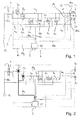
- the quasi-twin-circuit air suspension device has a supply air tank 11, which is pneumatically connected to a level control valve unit 1 via a pneumatic line 10e.
- a control valve device 3 comprising two check valves 5a, 5b, two vent valves 6a, 6b and two vent valves 7a, 7b, is connected downstream of the level control valve unit 1 pneumatically.
- air distribution unit 12 arranged on the control valve device 3 air spring bellows 2 a, 2 b, which are arranged on vehicle axles (not illustrated here), are pneumatically connected indirectly via the level control valve unit 1 and the control valve device 3 to the supply air tank 11.
- Dual-circuit means that the left-side and the right-side bellows 2 a, 2 b can be ventilated or completely separated from one another.
- the control valve device 3 is for manual level adjustment of the vehicle body, bypassing the level control valve unit 1 with a manual control unit 8, comprising a single manual operating element 9 and a valve unit 15, pneumatically connected.
- pneumatic lines 10a, 10b, 10c are formed between the control valve device 3 and the manual control unit 8, which pneumatically connects the valve unit 15 with the respective two check valves 5a, 5b, respectively the two vent valves 6a, 6b and the respective two vent valves 7a, 7b.
- a pneumatic line 10d serves the valve unit 15 as a pneumatic input and connects them indirectly with the storage air tank 11 and / or with the air spring bellows 2a, 2b through the check valves 4a, 4b.
- the control valve device 3 is advantageously arranged together with the air distribution unit 12 and the manual control unit 8 in a common housing 14.
- the manual operating element 9 is in a first position, so that the two check valves 5a, 5b, the two vent valves 6a, 6b and the two vent valves 7a, 7b, all as 2/2-way valves are formed, due to a pneumatic pressure in the pneumatic lines 10a, 10b, 10c are closed. Due to the two closed check valves 5a, 5b, neither via the pneumatic line 10g nor via the pneumatic line 10h compressed air from the supply air tank 11 via the level control valve unit 1 in the bellows 2a, 2b flow, regardless of the switching position of the level control valve 1.
- the air distribution unit 12 comprises a connection line 16, which connects the right and left side air spring bellows 2 a, 2 b by two throttles 17 a, 17 b. Between the two throttles 17a, 17b, a pressure average value is formed from the pressure values in the right-hand and left-side air spring bellows 2a, 2b. This pressure average is passed on the one hand through the control terminal 13 to the brake system of the vehicle EBS or to the brake system of the trailer TEBS and serves as an axle load signal. On the other hand, it is passed through the line 10i to a test port.
- the manual control unit 8 includes a connection line 10j, whereby a driving condition dependent signal is input to switch the valve unit 15 to the second position without manual intervention.
- FIG. 2 To FIG. 2 is the manual actuating element 9 in a second position, whereby the two check valves 5a, 5b, due to a venting of the pneumatic line 10a via the valve unit 15, are opened.
- the two vent valves 6a, 6b and the two vent valves 7a, 7b are closed.
- this operating state driving a flow of compressed air through the two check valves 5a, 5b from the storage air tank 11 in the Druckluftbälge 2a, 2b allows.
- level control valve unit 1 located between the check valves 5a, 5b and the Reservoir air tank 11 arranged level control valve unit 1 in the position Closed, so that neither compressed air in the Druckluftbälge 2a, 2b can still flow out.
- the position of the level control valve unit 1 is variable and changes with the vehicle height automatically, and further via the level control valve unit 1, a pneumatic connection between the pneumatic line 10e and the pneumatic lines 10g and 10h for lifting the vehicle body, ie an automatic return to a predetermined vehicle height , is feasible.
- the manual operating element 9 is in a third position, whereby the two vent valves 7a, 7b, due to a venting of the pneumatic line 10c via the valve unit 15, are open.
- the two vent valves 6a, 6b and the two check valves 5a, 5b are closed.
- lowering of the compressed air via the two venting valves 7a, 7b from the air bellows 2a, 2b is made possible, so that the vehicle body is lowered manually, bypassing the level control valve unit 1.
- the manual actuating element 9 is in a fourth position, whereby the two vent valves 6a, 6b, due to a venting of the pneumatic line 10b via the valve unit 15, are open.
- the two vent valves 7a, 7b and the two check valves 5a, 5b are closed.
- this operating state lifting it is possible for the compressed air to flow in via the two ventilation valves 6a, 6b into the air spring bellows 2a, 2b, so that the vehicle body is raised manually, bypassing the level control valve unit 1.
- the single-circuit air suspension device shown in FIG. 5 has a control valve device 3, comprising the check valve 5a, the vent valves 6a and the vent valves 7a, 7b.
- Single-circuit means in this context that the bellows 2a, 2b are associated with a circle and therefore only together can be ventilated and vented. Therefore, between the level control valve unit 1 and the bellows 2 a, 2 b, only one pneumatic line 10 g is arranged.
- the single manual operating element 9 is in a first position, so that the check valve 5a, the vent valve 6a and the vent valves 7a, 7b, which are all designed as 2/2-way valves, due to a pneumatic pressure in the pneumatic Lines 10a, 10b, 10c are closed.
- the two vent valves 7a, 7b are provided for rapid venting of the air spring bellows 2a, 2b and thus to the fast laces of the vehicle.
Landscapes
- Engineering & Computer Science (AREA)
- Mechanical Engineering (AREA)
- Vehicle Body Suspensions (AREA)
Priority Applications (3)
| Application Number | Priority Date | Filing Date | Title |
|---|---|---|---|
| RS20190165A RS58396B1 (sr) | 2014-06-18 | 2015-06-02 | Instalacija vazdušnog elastičnog oslanjanja za podizanje i spuštanje strukture vozila |
| SI201530604T SI2957441T1 (sl) | 2014-06-18 | 2015-06-02 | Pnevmatska vzmetna priprava za dviganje in spuščanje karoserije vozila |
| PL15170198T PL2957441T3 (pl) | 2014-06-18 | 2015-06-02 | Układ zawieszenia pneumatycznego do podnoszenia i opuszczania nadwozia pojazdu |
Applications Claiming Priority (1)
| Application Number | Priority Date | Filing Date | Title |
|---|---|---|---|
| DE102014108556.6A DE102014108556B4 (de) | 2014-06-18 | 2014-06-18 | Luftfederungseinrichtung zum Heben und Senken eines Fahrzeugaufbaus |
Publications (2)
| Publication Number | Publication Date |
|---|---|
| EP2957441A1 true EP2957441A1 (fr) | 2015-12-23 |
| EP2957441B1 EP2957441B1 (fr) | 2018-11-21 |
Family
ID=53385481
Family Applications (1)
| Application Number | Title | Priority Date | Filing Date |
|---|---|---|---|
| EP15170198.4A Active EP2957441B1 (fr) | 2014-06-18 | 2015-06-02 | Installation de ressort pneumatique destinée à lever et à abaisser une caisse de véhicule |
Country Status (10)
| Country | Link |
|---|---|
| EP (1) | EP2957441B1 (fr) |
| DE (1) | DE102014108556B4 (fr) |
| DK (1) | DK2957441T3 (fr) |
| ES (1) | ES2712374T3 (fr) |
| HU (1) | HUE041612T2 (fr) |
| PL (1) | PL2957441T3 (fr) |
| PT (1) | PT2957441T (fr) |
| RS (1) | RS58396B1 (fr) |
| SI (1) | SI2957441T1 (fr) |
| TR (1) | TR201902204T4 (fr) |
Cited By (1)
| Publication number | Priority date | Publication date | Assignee | Title |
|---|---|---|---|---|
| EP3695994A1 (fr) * | 2019-02-15 | 2020-08-19 | KNORR-BREMSE Systeme für Nutzfahrzeuge GmbH | Possibilités d'automatisation d'un système de suspension à ressort pneumatique de levage et d'abaissement |
Citations (14)
| Publication number | Priority date | Publication date | Assignee | Title |
|---|---|---|---|---|
| FR2279580A1 (fr) * | 1974-07-26 | 1976-02-20 | Daimler Benz Ag | Vehicule comportant un groupe de plusieurs essieux portant le chassis par l'intermediaire de ressorts de suspension utilisant la pression d'un fluide |
| WO1991006440A2 (fr) * | 1989-11-07 | 1991-05-16 | Rubery Owen-Rockwell Limited | Maintien de la hauteur d'un vehicule a suspension pneumatique |
| EP0435587A2 (fr) * | 1989-12-23 | 1991-07-03 | Ror Rockwell Limited | Système de suspension pneumatique multiessieux pour un véhicule |
| DE19916040A1 (de) * | 1999-04-09 | 2000-10-12 | Knorr Bremse Systeme | Ventilvorrichtung zum Heben und Senken von luftgefederten Anhänger-Fahrzeugen |
| ES2277765A1 (es) * | 2005-11-02 | 2007-07-16 | Accesorios Y Elevadores Valencia, S.L. | Metodo para control de suspension neumatica de vehiculos industriales y dispositivo correspondiente. |
| DE102006006439A1 (de) | 2006-02-13 | 2007-08-16 | Wabco Gmbh | Ventileinrichtung zur manuellen Veränderung der Niveaulage eines luftgefederten Fahrzeuges |
| DE102007008159A1 (de) * | 2007-02-19 | 2008-08-21 | Knorr-Bremse Systeme für Nutzfahrzeuge GmbH | Luftfederungseinrichtung mit elektrisch betätigtem Sperrventil |
| EP2070741A1 (fr) * | 2007-11-30 | 2009-06-17 | Haldex Brake Products GmbH | Système de suspension pneumatique d'un véhicule |
| EP2263892A1 (fr) | 2009-06-10 | 2010-12-22 | Haldex Brake Products GmbH | Unité de vanne de commande destinée à aérer et ventiler des soufflets à ressort d'un véhicule ou d'une remorque |
| DE102007008156B4 (de) | 2007-02-19 | 2011-03-31 | Knorr-Bremse Systeme für Nutzfahrzeuge GmbH | Luftfederungseinrichtung mit ausschließlich druckmittelbetätigten Steuerventilen und einer Höhenbegrenzungseinrichtung |
| WO2011076302A1 (fr) * | 2009-12-23 | 2011-06-30 | Wabco Gmbh & Co. Ohg | Dispositif de soupape destiné à un système d'amortisseur pneumatique |
| DE102006017890B4 (de) | 2005-04-16 | 2012-05-16 | Haldex Brake Products Gmbh | Schaltventil für Anlagen zum Heben und Senken eines Fahrzeugaufbaus |
| EP2540537A1 (fr) * | 2011-07-01 | 2013-01-02 | Haldex Brake Products GmbH | Installation de ressort pneumatique pour un véhicule utilitaire |
| EP2540536A1 (fr) * | 2011-07-01 | 2013-01-02 | Haldex Brake Products GmbH | Unité de soupape à régulation du niveau |
-
2014
- 2014-06-18 DE DE102014108556.6A patent/DE102014108556B4/de active Active
-
2015
- 2015-06-02 RS RS20190165A patent/RS58396B1/sr unknown
- 2015-06-02 EP EP15170198.4A patent/EP2957441B1/fr active Active
- 2015-06-02 PT PT15170198T patent/PT2957441T/pt unknown
- 2015-06-02 TR TR2019/02204T patent/TR201902204T4/tr unknown
- 2015-06-02 SI SI201530604T patent/SI2957441T1/sl unknown
- 2015-06-02 HU HUE15170198A patent/HUE041612T2/hu unknown
- 2015-06-02 DK DK15170198.4T patent/DK2957441T3/en active
- 2015-06-02 PL PL15170198T patent/PL2957441T3/pl unknown
- 2015-06-02 ES ES15170198T patent/ES2712374T3/es active Active
Patent Citations (14)
| Publication number | Priority date | Publication date | Assignee | Title |
|---|---|---|---|---|
| FR2279580A1 (fr) * | 1974-07-26 | 1976-02-20 | Daimler Benz Ag | Vehicule comportant un groupe de plusieurs essieux portant le chassis par l'intermediaire de ressorts de suspension utilisant la pression d'un fluide |
| WO1991006440A2 (fr) * | 1989-11-07 | 1991-05-16 | Rubery Owen-Rockwell Limited | Maintien de la hauteur d'un vehicule a suspension pneumatique |
| EP0435587A2 (fr) * | 1989-12-23 | 1991-07-03 | Ror Rockwell Limited | Système de suspension pneumatique multiessieux pour un véhicule |
| DE19916040A1 (de) * | 1999-04-09 | 2000-10-12 | Knorr Bremse Systeme | Ventilvorrichtung zum Heben und Senken von luftgefederten Anhänger-Fahrzeugen |
| DE102006017890B4 (de) | 2005-04-16 | 2012-05-16 | Haldex Brake Products Gmbh | Schaltventil für Anlagen zum Heben und Senken eines Fahrzeugaufbaus |
| ES2277765A1 (es) * | 2005-11-02 | 2007-07-16 | Accesorios Y Elevadores Valencia, S.L. | Metodo para control de suspension neumatica de vehiculos industriales y dispositivo correspondiente. |
| DE102006006439A1 (de) | 2006-02-13 | 2007-08-16 | Wabco Gmbh | Ventileinrichtung zur manuellen Veränderung der Niveaulage eines luftgefederten Fahrzeuges |
| DE102007008159A1 (de) * | 2007-02-19 | 2008-08-21 | Knorr-Bremse Systeme für Nutzfahrzeuge GmbH | Luftfederungseinrichtung mit elektrisch betätigtem Sperrventil |
| DE102007008156B4 (de) | 2007-02-19 | 2011-03-31 | Knorr-Bremse Systeme für Nutzfahrzeuge GmbH | Luftfederungseinrichtung mit ausschließlich druckmittelbetätigten Steuerventilen und einer Höhenbegrenzungseinrichtung |
| EP2070741A1 (fr) * | 2007-11-30 | 2009-06-17 | Haldex Brake Products GmbH | Système de suspension pneumatique d'un véhicule |
| EP2263892A1 (fr) | 2009-06-10 | 2010-12-22 | Haldex Brake Products GmbH | Unité de vanne de commande destinée à aérer et ventiler des soufflets à ressort d'un véhicule ou d'une remorque |
| WO2011076302A1 (fr) * | 2009-12-23 | 2011-06-30 | Wabco Gmbh & Co. Ohg | Dispositif de soupape destiné à un système d'amortisseur pneumatique |
| EP2540537A1 (fr) * | 2011-07-01 | 2013-01-02 | Haldex Brake Products GmbH | Installation de ressort pneumatique pour un véhicule utilitaire |
| EP2540536A1 (fr) * | 2011-07-01 | 2013-01-02 | Haldex Brake Products GmbH | Unité de soupape à régulation du niveau |
Cited By (2)
| Publication number | Priority date | Publication date | Assignee | Title |
|---|---|---|---|---|
| EP3695994A1 (fr) * | 2019-02-15 | 2020-08-19 | KNORR-BREMSE Systeme für Nutzfahrzeuge GmbH | Possibilités d'automatisation d'un système de suspension à ressort pneumatique de levage et d'abaissement |
| WO2020164890A1 (fr) * | 2019-02-15 | 2020-08-20 | Knorr-Bremse Systeme für Nutzfahrzeuge GmbH | Possibilités d'automatisation d'un système de suspension à ressort pneumatique d'élévation et d'abaissement |
Also Published As
| Publication number | Publication date |
|---|---|
| EP2957441B1 (fr) | 2018-11-21 |
| PL2957441T3 (pl) | 2019-05-31 |
| SI2957441T1 (sl) | 2019-03-29 |
| HUE041612T2 (hu) | 2019-05-28 |
| DE102014108556B4 (de) | 2021-04-22 |
| PT2957441T (pt) | 2019-02-18 |
| DK2957441T3 (en) | 2019-03-04 |
| ES2712374T3 (es) | 2019-05-13 |
| DE102014108556A1 (de) | 2016-01-14 |
| RS58396B1 (sr) | 2019-04-30 |
| TR201902204T4 (tr) | 2019-03-21 |
Similar Documents
| Publication | Publication Date | Title |
|---|---|---|
| EP3112230B1 (fr) | Module de frein de stationnement, installation de freinage et vehicule ainsi equipe et procede de fonctionnement d'un dispositif de frein de stationnement avec un tel module | |
| EP2125398B1 (fr) | Système de suspension pneumatique pourvu de soupapes de commande actionnées exclusivement par un fluide sous pression | |
| EP3129265B1 (fr) | Dispositif de commande électromagnétique de frein destiné à commander un frein à ressort accumulateur | |
| DE102007008159B4 (de) | Luftfederungseinrichtung mit elektrisch betätigtem Sperrventil | |
| EP2757006B1 (fr) | Système de soupape pour une installation d'air comprimé d'une remorque de véhicule utilitaire | |
| DE102012107203B4 (de) | Pneumatische Bremseinrichtung eines Fahrzeugs mit vom Parkbremsventil zwangsgesteuerter Interlock-Einrichtung | |
| EP3371017A1 (fr) | Dispositif de freinage pneumatique pour véhicule utilitaire | |
| EP3010772B2 (fr) | Dispositif de commande permettant de commander les freins d'une combinaison entre un véhicule tracteur et une remorque | |
| DE102011051505C5 (de) | Niveauregelventileinheit mit integriertem Verteiler | |
| DE102016102278A1 (de) | Relaisventileinrichtung einer pneumatischen oder elektro-pneumatischen Kraftfahrzeugbremseinrichtung | |
| DE102012105136A1 (de) | Steuereinrichtung zur Steuerung der Bremsen einer Zugfahrzeug-Anhängerkombination | |
| EP3112231A1 (fr) | Module de frein de stationnement, installation de freinage et vehicule ainsi equipe et procede de fonctionnement d'un dispositif de frein de stationnement avec un tel module | |
| DE3028472A1 (de) | Steuerung einer luftgefederten, anhebbaren und absenkbaren nachlaufachse eines nutzkraftfahrzeugs | |
| EP2177381B1 (fr) | Ensemble de clapets pour un système de suspension pneumatique | |
| DE69014487T2 (de) | Druckluftbremsanlage. | |
| EP2572909B1 (fr) | Systeme de soupapes destine a un systeme de suspension pneumatique d'un vehicule | |
| EP2957442B1 (fr) | Installation de ressort pneumatique destinée à lever et à abaisser une caisse de véhicule | |
| DE102010010605B4 (de) | Vorrichtung zur Steuerung von pneumatischen Einrichtungen eines Anhängers | |
| DE10158065B4 (de) | Redundanzdruck-Umschaltventil für elektronisch-pneumatische Bremsanlage | |
| EP2957441B1 (fr) | Installation de ressort pneumatique destinée à lever et à abaisser une caisse de véhicule | |
| DE102008051205A1 (de) | Ventileinrichtung für eine Luftfederungsanlage | |
| DE102005030467A1 (de) | Luftfederungseinrichtung für Fahrzeuge mit Drossel | |
| DE102010018614B3 (de) | Steuereinheit zum Erzeugen eines einen Fahrzustand eines Fahrzeugs kennzeichnenden Drucksignals |
Legal Events
| Date | Code | Title | Description |
|---|---|---|---|
| PUAI | Public reference made under article 153(3) epc to a published international application that has entered the european phase |
Free format text: ORIGINAL CODE: 0009012 |
|
| AK | Designated contracting states |
Kind code of ref document: A1 Designated state(s): AL AT BE BG CH CY CZ DE DK EE ES FI FR GB GR HR HU IE IS IT LI LT LU LV MC MK MT NL NO PL PT RO RS SE SI SK SM TR |
|
| AX | Request for extension of the european patent |
Extension state: BA ME |
|
| 17P | Request for examination filed |
Effective date: 20160623 |
|
| RBV | Designated contracting states (corrected) |
Designated state(s): AL AT BE BG CH CY CZ DE DK EE ES FI FR GB GR HR HU IE IS IT LI LT LU LV MC MK MT NL NO PL PT RO RS SE SI SK SM TR |
|
| GRAP | Despatch of communication of intention to grant a patent |
Free format text: ORIGINAL CODE: EPIDOSNIGR1 |
|
| STAA | Information on the status of an ep patent application or granted ep patent |
Free format text: STATUS: GRANT OF PATENT IS INTENDED |
|
| INTG | Intention to grant announced |
Effective date: 20180614 |
|
| GRAS | Grant fee paid |
Free format text: ORIGINAL CODE: EPIDOSNIGR3 |
|
| GRAA | (expected) grant |
Free format text: ORIGINAL CODE: 0009210 |
|
| STAA | Information on the status of an ep patent application or granted ep patent |
Free format text: STATUS: THE PATENT HAS BEEN GRANTED |
|
| AK | Designated contracting states |
Kind code of ref document: B1 Designated state(s): AL AT BE BG CH CY CZ DE DK EE ES FI FR GB GR HR HU IE IS IT LI LT LU LV MC MK MT NL NO PL PT RO RS SE SI SK SM TR |
|
| REG | Reference to a national code |
Ref country code: CH Ref legal event code: EP |
|
| REG | Reference to a national code |
Ref country code: IE Ref legal event code: FG4D Free format text: LANGUAGE OF EP DOCUMENT: GERMAN |
|
| REG | Reference to a national code |
Ref country code: DE Ref legal event code: R096 Ref document number: 502015006907 Country of ref document: DE |
|
| REG | Reference to a national code |
Ref country code: AT Ref legal event code: REF Ref document number: 1067124 Country of ref document: AT Kind code of ref document: T Effective date: 20181215 |
|
| REG | Reference to a national code |
Ref country code: CH Ref legal event code: NV Representative=s name: ISLER AND PEDRAZZINI AG, CH |
|
| REG | Reference to a national code |
Ref country code: PT Ref legal event code: SC4A Ref document number: 2957441 Country of ref document: PT Date of ref document: 20190218 Kind code of ref document: T Free format text: AVAILABILITY OF NATIONAL TRANSLATION Effective date: 20190212 Ref country code: RO Ref legal event code: EPE |
|
| REG | Reference to a national code |
Ref country code: DK Ref legal event code: T3 Effective date: 20190225 |
|
| REG | Reference to a national code |
Ref country code: SE Ref legal event code: TRGR |
|
| REG | Reference to a national code |
Ref country code: NL Ref legal event code: FP |
|
| PG25 | Lapsed in a contracting state [announced via postgrant information from national office to epo] |
Ref country code: IS Free format text: LAPSE BECAUSE OF FAILURE TO SUBMIT A TRANSLATION OF THE DESCRIPTION OR TO PAY THE FEE WITHIN THE PRESCRIBED TIME-LIMIT Effective date: 20190321 Ref country code: LV Free format text: LAPSE BECAUSE OF FAILURE TO SUBMIT A TRANSLATION OF THE DESCRIPTION OR TO PAY THE FEE WITHIN THE PRESCRIBED TIME-LIMIT Effective date: 20181121 Ref country code: HR Free format text: LAPSE BECAUSE OF FAILURE TO SUBMIT A TRANSLATION OF THE DESCRIPTION OR TO PAY THE FEE WITHIN THE PRESCRIBED TIME-LIMIT Effective date: 20181121 Ref country code: LT Free format text: LAPSE BECAUSE OF FAILURE TO SUBMIT A TRANSLATION OF THE DESCRIPTION OR TO PAY THE FEE WITHIN THE PRESCRIBED TIME-LIMIT Effective date: 20181121 Ref country code: BG Free format text: LAPSE BECAUSE OF FAILURE TO SUBMIT A TRANSLATION OF THE DESCRIPTION OR TO PAY THE FEE WITHIN THE PRESCRIBED TIME-LIMIT Effective date: 20190221 |
|
| REG | Reference to a national code |
Ref country code: NO Ref legal event code: T2 Effective date: 20181121 |
|
| REG | Reference to a national code |
Ref country code: ES Ref legal event code: FG2A Ref document number: 2712374 Country of ref document: ES Kind code of ref document: T3 Effective date: 20190513 |
|
| REG | Reference to a national code |
Ref country code: HU Ref legal event code: AG4A Ref document number: E041612 Country of ref document: HU |
|
| PG25 | Lapsed in a contracting state [announced via postgrant information from national office to epo] |
Ref country code: AL Free format text: LAPSE BECAUSE OF FAILURE TO SUBMIT A TRANSLATION OF THE DESCRIPTION OR TO PAY THE FEE WITHIN THE PRESCRIBED TIME-LIMIT Effective date: 20181121 Ref country code: GR Free format text: LAPSE BECAUSE OF FAILURE TO SUBMIT A TRANSLATION OF THE DESCRIPTION OR TO PAY THE FEE WITHIN THE PRESCRIBED TIME-LIMIT Effective date: 20190222 |
|
| REG | Reference to a national code |
Ref country code: SK Ref legal event code: T3 Ref document number: E 30182 Country of ref document: SK |
|
| REG | Reference to a national code |
Ref country code: DE Ref legal event code: R097 Ref document number: 502015006907 Country of ref document: DE |
|
| PG25 | Lapsed in a contracting state [announced via postgrant information from national office to epo] |
Ref country code: SM Free format text: LAPSE BECAUSE OF FAILURE TO SUBMIT A TRANSLATION OF THE DESCRIPTION OR TO PAY THE FEE WITHIN THE PRESCRIBED TIME-LIMIT Effective date: 20181121 Ref country code: EE Free format text: LAPSE BECAUSE OF FAILURE TO SUBMIT A TRANSLATION OF THE DESCRIPTION OR TO PAY THE FEE WITHIN THE PRESCRIBED TIME-LIMIT Effective date: 20181121 |
|
| PLBE | No opposition filed within time limit |
Free format text: ORIGINAL CODE: 0009261 |
|
| STAA | Information on the status of an ep patent application or granted ep patent |
Free format text: STATUS: NO OPPOSITION FILED WITHIN TIME LIMIT |
|
| 26N | No opposition filed |
Effective date: 20190822 |
|
| PG25 | Lapsed in a contracting state [announced via postgrant information from national office to epo] |
Ref country code: MC Free format text: LAPSE BECAUSE OF FAILURE TO SUBMIT A TRANSLATION OF THE DESCRIPTION OR TO PAY THE FEE WITHIN THE PRESCRIBED TIME-LIMIT Effective date: 20181121 |
|
| PG25 | Lapsed in a contracting state [announced via postgrant information from national office to epo] |
Ref country code: LU Free format text: LAPSE BECAUSE OF NON-PAYMENT OF DUE FEES Effective date: 20190602 |
|
| PGFP | Annual fee paid to national office [announced via postgrant information from national office to epo] |
Ref country code: NO Payment date: 20200623 Year of fee payment: 6 Ref country code: TR Payment date: 20200601 Year of fee payment: 6 Ref country code: DK Payment date: 20200622 Year of fee payment: 6 Ref country code: RO Payment date: 20200521 Year of fee payment: 6 Ref country code: PT Payment date: 20200526 Year of fee payment: 6 Ref country code: FI Payment date: 20200618 Year of fee payment: 6 Ref country code: CZ Payment date: 20200521 Year of fee payment: 6 Ref country code: IE Payment date: 20200618 Year of fee payment: 6 |
|
| PGFP | Annual fee paid to national office [announced via postgrant information from national office to epo] |
Ref country code: HU Payment date: 20200520 Year of fee payment: 6 Ref country code: RS Payment date: 20200521 Year of fee payment: 6 Ref country code: SK Payment date: 20200521 Year of fee payment: 6 Ref country code: SI Payment date: 20200522 Year of fee payment: 6 Ref country code: BE Payment date: 20200622 Year of fee payment: 6 Ref country code: SE Payment date: 20200625 Year of fee payment: 6 |
|
| PGFP | Annual fee paid to national office [announced via postgrant information from national office to epo] |
Ref country code: ES Payment date: 20200717 Year of fee payment: 6 |
|
| PGFP | Annual fee paid to national office [announced via postgrant information from national office to epo] |
Ref country code: CH Payment date: 20200630 Year of fee payment: 6 |
|
| PG25 | Lapsed in a contracting state [announced via postgrant information from national office to epo] |
Ref country code: CY Free format text: LAPSE BECAUSE OF FAILURE TO SUBMIT A TRANSLATION OF THE DESCRIPTION OR TO PAY THE FEE WITHIN THE PRESCRIBED TIME-LIMIT Effective date: 20181121 |
|
| PG25 | Lapsed in a contracting state [announced via postgrant information from national office to epo] |
Ref country code: MT Free format text: LAPSE BECAUSE OF FAILURE TO SUBMIT A TRANSLATION OF THE DESCRIPTION OR TO PAY THE FEE WITHIN THE PRESCRIBED TIME-LIMIT Effective date: 20181121 |
|
| PGFP | Annual fee paid to national office [announced via postgrant information from national office to epo] |
Ref country code: FR Payment date: 20210621 Year of fee payment: 7 Ref country code: NL Payment date: 20210621 Year of fee payment: 7 Ref country code: IT Payment date: 20210630 Year of fee payment: 7 |
|
| PGFP | Annual fee paid to national office [announced via postgrant information from national office to epo] |
Ref country code: PL Payment date: 20210521 Year of fee payment: 7 Ref country code: AT Payment date: 20210618 Year of fee payment: 7 Ref country code: GB Payment date: 20210623 Year of fee payment: 7 |
|
| REG | Reference to a national code |
Ref country code: FI Ref legal event code: MAE |
|
| REG | Reference to a national code |
Ref country code: NO Ref legal event code: MMEP Ref country code: DK Ref legal event code: EBP Effective date: 20210630 |
|
| REG | Reference to a national code |
Ref country code: SE Ref legal event code: EUG |
|
| PG25 | Lapsed in a contracting state [announced via postgrant information from national office to epo] |
Ref country code: CZ Free format text: LAPSE BECAUSE OF NON-PAYMENT OF DUE FEES Effective date: 20210602 Ref country code: RS Free format text: LAPSE BECAUSE OF NON-PAYMENT OF DUE FEES Effective date: 20210602 Ref country code: RO Free format text: LAPSE BECAUSE OF NON-PAYMENT OF DUE FEES Effective date: 20210602 Ref country code: PT Free format text: LAPSE BECAUSE OF NON-PAYMENT OF DUE FEES Effective date: 20211202 Ref country code: FI Free format text: LAPSE BECAUSE OF NON-PAYMENT OF DUE FEES Effective date: 20210602 |
|
| REG | Reference to a national code |
Ref country code: CH Ref legal event code: PL |
|
| REG | Reference to a national code |
Ref country code: SK Ref legal event code: MM4A Ref document number: E 30182 Country of ref document: SK Effective date: 20210602 |
|
| PG25 | Lapsed in a contracting state [announced via postgrant information from national office to epo] |
Ref country code: SI Free format text: LAPSE BECAUSE OF NON-PAYMENT OF DUE FEES Effective date: 20210603 |
|
| REG | Reference to a national code |
Ref country code: SI Ref legal event code: KO00 Effective date: 20220127 |
|
| REG | Reference to a national code |
Ref country code: BE Ref legal event code: MM Effective date: 20210630 |
|
| PG25 | Lapsed in a contracting state [announced via postgrant information from national office to epo] |
Ref country code: LI Free format text: LAPSE BECAUSE OF NON-PAYMENT OF DUE FEES Effective date: 20210630 Ref country code: IE Free format text: LAPSE BECAUSE OF NON-PAYMENT OF DUE FEES Effective date: 20210602 Ref country code: HU Free format text: LAPSE BECAUSE OF NON-PAYMENT OF DUE FEES Effective date: 20210603 Ref country code: CH Free format text: LAPSE BECAUSE OF NON-PAYMENT OF DUE FEES Effective date: 20210630 |
|
| PG25 | Lapsed in a contracting state [announced via postgrant information from national office to epo] |
Ref country code: SK Free format text: LAPSE BECAUSE OF NON-PAYMENT OF DUE FEES Effective date: 20210602 Ref country code: SE Free format text: LAPSE BECAUSE OF NON-PAYMENT OF DUE FEES Effective date: 20210603 Ref country code: NO Free format text: LAPSE BECAUSE OF NON-PAYMENT OF DUE FEES Effective date: 20210630 |
|
| PG25 | Lapsed in a contracting state [announced via postgrant information from national office to epo] |
Ref country code: MK Free format text: LAPSE BECAUSE OF FAILURE TO SUBMIT A TRANSLATION OF THE DESCRIPTION OR TO PAY THE FEE WITHIN THE PRESCRIBED TIME-LIMIT Effective date: 20181121 |
|
| PG25 | Lapsed in a contracting state [announced via postgrant information from national office to epo] |
Ref country code: DK Free format text: LAPSE BECAUSE OF NON-PAYMENT OF DUE FEES Effective date: 20210630 Ref country code: BE Free format text: LAPSE BECAUSE OF NON-PAYMENT OF DUE FEES Effective date: 20210630 |
|
| REG | Reference to a national code |
Ref country code: ES Ref legal event code: FD2A Effective date: 20220802 |
|
| PG25 | Lapsed in a contracting state [announced via postgrant information from national office to epo] |
Ref country code: ES Free format text: LAPSE BECAUSE OF NON-PAYMENT OF DUE FEES Effective date: 20210603 |
|
| REG | Reference to a national code |
Ref country code: NL Ref legal event code: MM Effective date: 20220701 |
|
| REG | Reference to a national code |
Ref country code: AT Ref legal event code: MM01 Ref document number: 1067124 Country of ref document: AT Kind code of ref document: T Effective date: 20220602 |
|
| GBPC | Gb: european patent ceased through non-payment of renewal fee |
Effective date: 20220602 |
|
| PG25 | Lapsed in a contracting state [announced via postgrant information from national office to epo] |
Ref country code: NL Free format text: LAPSE BECAUSE OF NON-PAYMENT OF DUE FEES Effective date: 20220701 |
|
| PG25 | Lapsed in a contracting state [announced via postgrant information from national office to epo] |
Ref country code: FR Free format text: LAPSE BECAUSE OF NON-PAYMENT OF DUE FEES Effective date: 20220630 Ref country code: AT Free format text: LAPSE BECAUSE OF NON-PAYMENT OF DUE FEES Effective date: 20220602 |
|
| PG25 | Lapsed in a contracting state [announced via postgrant information from national office to epo] |
Ref country code: GB Free format text: LAPSE BECAUSE OF NON-PAYMENT OF DUE FEES Effective date: 20220602 |
|
| P01 | Opt-out of the competence of the unified patent court (upc) registered |
Effective date: 20230508 |
|
| PG25 | Lapsed in a contracting state [announced via postgrant information from national office to epo] |
Ref country code: IT Free format text: LAPSE BECAUSE OF NON-PAYMENT OF DUE FEES Effective date: 20220602 |
|
| PG25 | Lapsed in a contracting state [announced via postgrant information from national office to epo] |
Ref country code: PL Free format text: LAPSE BECAUSE OF NON-PAYMENT OF DUE FEES Effective date: 20220602 |
|
| PGFP | Annual fee paid to national office [announced via postgrant information from national office to epo] |
Ref country code: DE Payment date: 20250626 Year of fee payment: 11 |