EP2957501B1 - Système de régulation de longueur d'entretoise et de pression - Google Patents
Système de régulation de longueur d'entretoise et de pression Download PDFInfo
- Publication number
- EP2957501B1 EP2957501B1 EP15171673.5A EP15171673A EP2957501B1 EP 2957501 B1 EP2957501 B1 EP 2957501B1 EP 15171673 A EP15171673 A EP 15171673A EP 2957501 B1 EP2957501 B1 EP 2957501B1
- Authority
- EP
- European Patent Office
- Prior art keywords
- strut
- valve
- controller
- pressure
- response
- Prior art date
- Legal status (The legal status is an assumption and is not a legal conclusion. Google has not performed a legal analysis and makes no representation as to the accuracy of the status listed.)
- Active
Links
Images



Classifications
-
- B—PERFORMING OPERATIONS; TRANSPORTING
- B64—AIRCRAFT; AVIATION; COSMONAUTICS
- B64C—AEROPLANES; HELICOPTERS
- B64C25/00—Alighting gear
- B64C25/32—Alighting gear characterised by elements which contact the ground or similar surface
- B64C25/58—Arrangements or adaptations of shock-absorbers or springs
- B64C25/62—Spring shock-absorbers; Springs
-
- B—PERFORMING OPERATIONS; TRANSPORTING
- B64—AIRCRAFT; AVIATION; COSMONAUTICS
- B64C—AEROPLANES; HELICOPTERS
- B64C25/00—Alighting gear
- B64C25/02—Undercarriages
- B64C25/08—Undercarriages non-fixed, e.g. jettisonable
- B64C25/10—Undercarriages non-fixed, e.g. jettisonable retractable, foldable, or the like
- B64C25/18—Operating mechanisms
- B64C25/22—Operating mechanisms fluid
-
- B—PERFORMING OPERATIONS; TRANSPORTING
- B64—AIRCRAFT; AVIATION; COSMONAUTICS
- B64C—AEROPLANES; HELICOPTERS
- B64C25/00—Alighting gear
- B64C25/32—Alighting gear characterised by elements which contact the ground or similar surface
- B64C25/58—Arrangements or adaptations of shock-absorbers or springs
- B64C25/60—Oleo legs
-
- F—MECHANICAL ENGINEERING; LIGHTING; HEATING; WEAPONS; BLASTING
- F16—ENGINEERING ELEMENTS AND UNITS; GENERAL MEASURES FOR PRODUCING AND MAINTAINING EFFECTIVE FUNCTIONING OF MACHINES OR INSTALLATIONS; THERMAL INSULATION IN GENERAL
- F16F—SPRINGS; SHOCK-ABSORBERS; MEANS FOR DAMPING VIBRATION
- F16F9/00—Springs, vibration-dampers, shock-absorbers, or similarly-constructed movement-dampers using a fluid or the equivalent as damping medium
- F16F9/02—Springs, vibration-dampers, shock-absorbers, or similarly-constructed movement-dampers using a fluid or the equivalent as damping medium using gas only or vacuum
- F16F9/0209—Telescopic
-
- F—MECHANICAL ENGINEERING; LIGHTING; HEATING; WEAPONS; BLASTING
- F16—ENGINEERING ELEMENTS AND UNITS; GENERAL MEASURES FOR PRODUCING AND MAINTAINING EFFECTIVE FUNCTIONING OF MACHINES OR INSTALLATIONS; THERMAL INSULATION IN GENERAL
- F16F—SPRINGS; SHOCK-ABSORBERS; MEANS FOR DAMPING VIBRATION
- F16F9/00—Springs, vibration-dampers, shock-absorbers, or similarly-constructed movement-dampers using a fluid or the equivalent as damping medium
- F16F9/02—Springs, vibration-dampers, shock-absorbers, or similarly-constructed movement-dampers using a fluid or the equivalent as damping medium using gas only or vacuum
- F16F9/0209—Telescopic
- F16F9/0245—Means for adjusting the length of, or for locking, the spring or dampers
Definitions
- the present disclosure relates to landing gear systems and, more specifically, to a system to regulate the length and pressure of the landing gear shock strut.
- Aircraft landing gear often includes shock struts.
- a shock strut often contains gas and/or oil and provides shock absorption to the landing gear.
- temperature variations have an adverse effect on the shock strut because they change the pressure at which the gas is maintained. This change alters the resting length/internal pressure of the shock strut, and thus the performance characteristics of the shock strut.
- EP 0365317 A1 relates to a pneumatic die cushion equipment.
- US 2010/0037957 A1 relates to a method and a device for the activation of an electropneumatic valve of a pressure medium-actuable position controller.
- US 2012/053783 A1 relates to monitoring landing gear strut fluid levels.
- WO 2008/063685 A2 pertains to a landing gear with adjustable ride height.
- a strut length and pressure regulation system according to claim 1 is disclosed.
- a method of strut length and pressure regulation according to claim 2 is disclosed.
- any reference to singular includes plural embodiments, and any reference to more than one component or step may include a singular embodiment or step.
- any reference to attached, fixed, connected or the like may include permanent, removable, temporary, partial, full and/or any other possible attachment option.
- any reference to without contact may also include reduced contact or minimal contact.
- phrases such as "make contact with,” “coupled to,” “touch,” “interface with” and “engage” may be used interchangeably.
- to be connected in “fluid communication” or “fluidic communication” or to be in “fluidic interconnection” means that a passage exists between the connected elements via which a fluid, including a gas and/or a liquid and/or any other non-solid matter, may pass from one connected element to another connected element.
- a fluid including a gas and/or a liquid and/or any other non-solid matter
- electrical communication or “electrical interconnection” may refer to any electrical, electromagnetic, radio frequency and/or optical method whereby information may be conveyed.
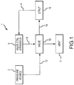
- a strut length and pressure regulation system 1 may comprise a pressure source 2, a valve control apparatus 6, a valve 10, and a strut 16.
- the system may operate to increase or decrease the amount of a gas in the strut 16 in order to lengthen or shorten the strut 16 and/or to maintain the air spring of the strut at different operating temperatures.
- Gas may be directed from the pressure source 2, through the valve 10, and into the strut 16, or gas may be released by the valve 10 from the strut 16 and vented via vent 11 at the direction of the valve control apparatus 6.
- a pressure source 2 may comprise a gas reservoir, for example, a storage tank.
- the pressure source 2 comprises a nitrogen tank, though the pressure source 2 may also comprise a source of compressed air, such as an air compressor, or any other source whereby gas may be provided at a pressure sufficiently high to flow into the strut 16 in response to a load being placed on the strut 16.
- the strut 16 is an aircraft landing gear shock strut, thus the pressure may be sufficiently high to overcome the nominal gas pressure inside the strut 16 when supporting the weight of the aircraft.
- a valve 10 may comprise a mechanism whereby the strut 16 may be connected in fluidic communication with one or more gas sources.
- the valve 10 may be a three position valve.
- the valve 10 may be operated to connect the strut 16 in fluidic communication with a pressure source 2, or to connect the strut 16 in fluidic communication with the ambient environment, or may be operated to fluidically isolate the strut 16, disconnecting the strut 16 from fluidic communication with the environment or other systems.
- “close” or “disconnect” means to move toward 100% closed, or disconnected, and "open” or “connect” means to move toward 100% opened.
- a vent 11 may comprise any device whereby a fluid may be released.
- the vent 11 may be an aperture disposed in fluid communication with the ambient environment.
- the vent 11 may comprise a collection reservoir configured to receive waste fluid and/or another aircraft system where the fluid may be repurposed.
- the vent 11 may comprise any device whereby gas released from the strut 16 may be purged from the strut length and pressure regulation system 1.
- a valve control apparatus 6 may comprise any device whereby the position of the valve 10 may be controlled.
- the valve control apparatus 6 may be electronic.
- the valve control apparatus 6 may be mechanical.
- Various embodiments of the valve control apparatus 6 are discussed further herein.
- a strut 16 may comprise an aircraft landing gear shock strut.
- a strut 16 may comprise a strut of a nose gear portion of the landing gear, or a strut of a main gear portion of the landing gear, or may comprise various struts of various portions of the landing gear.
- a strut 16 may comprise an automotive strut, or may comprise an industrial strut, or may comprise any strut 16 for which regulation of strut length/pressure is desired.
- the strut length and pressure regulation system 1 may comprise various electrical, logical, mechanical, and/or fluidic interconnections.
- a first valve input interconnection 12 may be disposed between the pressure source 2 and the valve 10.
- the first valve input interconnection 12 may provide a path for gas to travel from the pressure source 2 to the valve 10.
- the first valve input interconnection 12 comprises a tubing.
- the first valve input interconnection 12 may comprises any apparatus by which the pressure source 2 may be maintained in fluidic communication with the valve 10.
- valve 10 may be interconnected with the strut 16.
- a first valve output interconnection 14 may be disposed between the valve 10 and the strut 16.
- the first valve output interconnection 14 may provide a path for gas to travel from the valve 10 to the strut 16.
- the first valve output interconnection 14 comprises a tubing.
- the first valve output interconnection 14 may comprise any apparatus by which the strut 16 may be maintained in fluidic communication with the valve 10.
- the first valve output interconnection 14 provides a path whereby gas may travel from the valve 10 to the strut 16, and by which gas may travel from the strut 16 to the valve 10.
- the valve 10 may operate to selectively put the first valve output interconnection 14 in fluidic communication with the first valve input interconnection 12 and/or the surrounding environment.
- a strut condition feedback interconnection 4 may be disposed between the strut 16 and the valve control apparatus 6.
- the strut condition feedback interconnection 4 may comprise any sensing apparatus whereby the valve control apparatus 6 may receive an indication from the strut 16 of the strut's condition.
- the length of the strut 16 may be provided to the valve control apparatus 6.
- the pressure of the gas inside the strut 16 may be provided to the valve control apparatus 6.
- the pressure of the gas inside the strut 16 and the length of the strut 16 may be provided to the valve control apparatus 6.
- the valve control apparatus 6 may send valve control instructions 8 to control the valve 10 in response to this information provided via the strut condition feedback interconnection 4.
- the strut condition feedback interconnection 4 may comprise an electrical connection to a sensor proximate to the strut 16, or may comprise electrical connections to multiple sensors proximate to the strut 16, or may comprise a fluidic connection to a mechanical device, for example, so that the pressure of the gas inside the strut 16 may be conveyed to the valve control apparatus 6.
- a valve control apparatus 6 may be an electronic valve control apparatus.
- the valve control apparatus 6 may comprise a controller 28, a strut position sensor 34, and a strut pressure sensor 38.
- Controller 28 may have a processor and a tangible, nontransitory memory.
- the controller 28 may accept various inputs and perform certain logical processes in response to the inputs.
- the controller 28 may provide various outputs in response to the logical processes.
- the controller 28 may receive data from the strut position sensor 34 and the strut pressure sensor 38.
- the controller 28 may control the valve 10 in response to a determination of whether to vary the amount of gas in a strut 16.
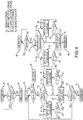
- several such logical processes for determining whether to vary the amount of gas in a strut 16 are illustrated in Fig. 4 .
- the controller 28 may be logical communication with an aircraft data source 24.
- Logical communication may include electrical, magnetic, radio frequency, and/or optical communication.
- Logical communication may facilitate the transmission of signals, whether analog or digital, between two or more components.
- Aircraft data source 24 may comprise an aircraft data bus, a global positioning system (“GPS”), a full authority digital engine control (“FADEC”), an electronic engine controller (“EEC”), an engine control unit (“ECU”), a flight computer, an airspeed indicator, an altimeter, a weight-on-wheels (“WOW”) switch, a parking brake position switch, and/or any other aircraft system, instrument, or data source whereby the status of the aircraft may be determined.
- the status of the aircraft may include information such as whether an aircraft is parked, taxiing, taking off, climbing, cruising, descending, and/or landing.
- the status of the aircraft may include information such as whether the aircraft landing gear is extended, whether the aircraft landing gear is retracted, whether the aircraft is on the ground, and whether the aircraft is in the air.
- Aircraft status information 26 may be provided by aircraft data source 24 to the controller 28. In this manner, the controller 28 may be made aware of the context in which the aircraft is operating.
- Controller 28 may also be in logical communication with strut position sensor 34.
- the controller 28 may receive a position signal 32 from strut position sensor 34 that indicates the length of a strut 16.
- the controller 28 may be in logical communication with strut pressure sensor 38.
- the controller 28 may receive a pressure signal 36 from the strut pressure sensor 38 that indicates the pressure of a gas inside the strut 16.
- a strut position sensor 34 may comprise a rotary variable differential transformer ("RVDT").
- the strut position sensor 34 may be disposed at an articulating joint of an aircraft landing gear torque link.
- the strut position sensor 34 may be disposed between an upper torque link 91 and a lower torque link 92 of a landing gear at the rotating joint therebetween.
- a rotary variable differential transformer disposed at this articulating joint may determine the length of the strut 16 and may provide a position signal 32 in response.
- a strut position sensor 34 may comprise a linear variable differential transformer ("LVDT") disposed parallel to the strut 16 whereby the LVDT may compress and extend in unison with the strut 16.
- LVDT linear variable differential transformer
- a strut position sensor 34 may comprise an optical sensor, or any other sensing device by which the length of the strut 16 may be measured, directly or indirectly, for various landing gear configurations.
- a strut pressure sensor 38 may comprise a piezoelectric pressure transducer, or an electromagnetic pressure sensor wherein the displacement of a diaphragm is measured, or may comprise any type of sensor whereby the pressure of a gas may be determined.
- the strut pressure sensor 38 may be disposed in fluidic communication with the strut 16.
- the strut pressure sensor 38 may determine the pressure of the gas within the strut 16 and may provide a pressure signal 36 in response.
- the strut pressure sensor 38 may comprise any sensing device by which the pressure of the gas in the strut 16 may be measured.
- a controller 28 may have logical states. For example, a controller 28 may have a system off state (beginning at step 40), a ground standby state (beginning at step 44), and an air standby state (beginning at step 48). From these states, the controller 28 may make various assessments and take various actions in response to inputs.
- a method for controlling a strut 16 may begin with the system in a system off state (step 40).
- the controller 28 may receive aircraft status information 26 from an aircraft data source 24 and assess this information to determine the status of the aircraft hydraulic system (step 42).
- the controller 28 may proceed to a ground standby state (step 44).
- a method for controlling a strut may include a ground standby state (step 44).
- the controller 28 may assess whether the landing gear is up or down, via receipt of aircraft status information 26. Upon a determination that the landing gear is up, the controller 28 may proceed to an air standby state (step 48). Upon a determination that the landing gear is down, the controller 28 may perform various assessments and take various actions in response to inputs. For example, the controller 28 may determine the length of a strut 16 in response to the position signal 32 from strut position sensor 34 (step 50).
- the controller 28 may determine if the length of a strut 16 is greater than a pre-programmed upper limit, is less than a pre-programmed lower limit, or is within a pre-programmed upper and lower limit (step 50).
- the controller 28 may also have a pre-programmed desired stroke length which lies between the upper limit and the lower limit. The controller 28 may take various actions in response to this determining.
- the controller 28 may proceed to step 58 and send valve control instructions 8 directing the valve 10 to connect the pressure source 2 to the strut 16 and charge the strut 16 with additional gas.
- the controller 28 may direct the valve 10 to maintain this connection until the position signal 32 from the strut position sensor 34 indicates (step 60) that the length of the strut 16 is the desired stroke length. Then, the controller 28 may send valve control instructions 8 directing the valve 10 to disconnect the pressure source 2 from the strut 16 and fluidically isolate the strut 16 (step 56).
- the controller 28 may proceed to step 52 and send valve control instructions 8 directing the valve 10 to connect the strut 16 to vent 11, permitting the strut 16 to vent to the ambient environment.
- the controller 28 may direct the valve 10 to maintain this connection until the position signal 32 from the strut position sensor 34 indicates (step 54) that the length is the desired stroke length.
- the controller 28 may send valve control instructions 8 directing the valve 10 to fluidically isolate the strut 16 (step 56).
- the controller 28 may send valve control instructions 8 directing the valve 10 to fluidically isolate the strut 16 (step 56).
- the controller 28 may re-assess the status of the aircraft hydraulic system (step 64). Upon a determination that the aircraft hydraulic system is active, the controller 28 may return to step 46. In this manner, the system may continually assess the strut 16 and adjust the gas in the strut 16 to maintain the length of the strut 16 in response to the strut length and pressure regulation system 1 being in the ground standby state.
- the system may switch to air standby state (step 48) in response to the aircraft status information 26 indicating that the landing gear is up (step 46).
- the strut length and pressure regulation system 1 operates to assess the landing gear status to evaluate whether the gear remains up or is extended down (Step 68).
- the strut length and pressure regulation system 1 takes additional steps.
- an air standby state may include the additional methods discussed below.
- the controller 28 may determine the pressure of the gas inside of a strut 16 in response to the pressure signal 36 from strut pressure sensor 38 (step 70). The controller 28 may determine if the pressure is greater than a desired pressure, is less than a desired pressure, or equals a desired pressure (step 70). The controller 28 may take various actions in response to this determining.
- “length regulation” and/or “pressure regulation” and/or “length and pressure regulation” includes the regulation of the length and/or amount of gas in the strut in response to an evaluation of the pressure of the gas in the strut, or the length of the strut, or the pressure of the gas in the strut and the length of the strut, depending on the system state and the various methods discussed herein.
- the controller 28 may proceed to step 78 and send valve control instructions 8 directing the valve 10 to connect the pressure source 2 to the strut 16 and charge the strut 16 with additional gas.
- the controller 28 may direct the valve 10 to maintain this connection until the pressure signal 36 from the strut pressure sensor 38 indicates (step 80) that the pressure equals the desired pressure. Then, the controller 28 sends valve control instructions 8 directing the valve 10 to disconnect the pressure source 2 from the strut 16 and fluidically isolate the strut 16 (step 76).
- the controller 28 may proceed to step 72 and send valve control instructions 8 directing the valve 10 to connect the strut 16 to the ambient environment (e.g., permit the strut 16 to vent).
- the controller 28 may direct the valve 10 to maintain this connection until the pressure signal 36 from the strut pressure sensor 38 indicates (step 74) that the length is the desired stroke length.
- the controller 28 may then send valve control instructions 8 directing the valve 10 to fluidically isolate the strut 16 (step 76).
- the controller 28 may send valve control instructions 8 directing the valve 10 to fluidically isolate the strut 16 (step 76). Subsequently the controller 28 may leave the air standby state and return to the system off state (step 40).
- the strut 16 may need to be charged with different amounts of gas to maintain a desired length and/or pressure.
- strut charge the amount of gas stored in the strut 16
- the strut length decreases.
- the amount of gas stored in the strut 16 must be increased (depicted as charging line 102).
- the valve control apparatus 6 may control the valve 10 ( Fig. 1 ) whereby the amount of gas in the strut 16 is changed responsively.
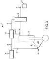
- a valve control apparatus 6 comprises a mechanical system integrated with the valve 10, rather than an electronic controller and various sensors ( Fig. 2 ).
- the valve control apparatus 6 may comprise a housing 22.
- the valve 10 may be integrated into this housing 22 and may share components with it.
- the valve 10 may comprise a floating piston 20 comprising a floating piston passage 21 and connected to a spring 18.
- the floating piston 20 may translate within the housing 22 alternately blocking a fluidic passage disposed between first valve input interconnection 12 and the first valve output interconnection 14 and aligning the floating piston passage 21 to complete a fluidic passage disposed between first valve input interconnection 12 and the first valve output interconnection 14. In this manner, the valve 10 may be opened and closed.
- the valve control apparatus 6 may comprise, in addition to the housing 22, a control reservoir 9 in fluidic communication with the floating piston 20.
- the valve control apparatus 6 may further comprise an orifice whereby the strut condition feedback interconnection 4 from the strut 16 may put the gas inside the strut 16 into fluidic communication with the floating piston 20.
- the pressure exerted on the floating piston 20 also becomes low and the floating piston 20 translates within housing 22 due to the force exerted by spring 18, unblocking a fluidic passage disposed between first valve input interconnection 12 and permitting gas to flow from pressure source 2 through first valve input interconnection 12, into the valve 10, and out the first valve output interconnection 14 into the strut 16.
- a valve control apparatus 6 may comprise a mechanical system.
- the strut condition feedback interconnection 4 comprises a fluidic interconnection between the strut 16 and the control reservoir 9 of the valve control apparatus 6, whereby the valve control instructions 8 operate the translatable floating piston 20.
- the valve control instructions 8 comprise the pressure of the fluid conveyed by this fluidic interconnection.
- an exemplary embodiment of a strut length and pressure regulation system 1 may comprise combinations of various features from various example embodiments disclosed herein.
- an exemplary embodiment of a strut length and pressure regulation system 1 may comprise a valve control apparatus 6 and valve 10 according to Fig. 2 , or according to Fig. 5 , or according to various other arrangements, for example, according to a combination of that disclosed in Figs. 2 and 5 or portions of that disclosed in Figs. 2 and 5 .
- a valve control apparatus 6 may comprise an electronic valve control apparatus of Fig. 2 , but the strut pressure sensor 38 may be omitted and a second valve control apparatus comprising that of Fig. 5 may also be implemented.
- a strut length and pressure regulation system 1 may be manufactured from various materials.
- a strut length and pressure regulation system 1 may comprise metal.
- a strut length and pressure regulation system 1 may comprise metal, such as titanium, aluminum, steel, or stainless steel, though it may alternatively comprise numerous other materials configured to provide support, such as, for example, composite, ceramic, plastics, polymers, alloys, glass, binder, epoxy, polyester, acrylic, or any material or combination of materials having a desired strength, stiffness, or flexibility sufficient to maintain resiliency during use.
- various portions of strut length and pressure regulation system 1 as disclosed herein are made of different materials or combinations of materials, and/or may comprise coatings.
- strut length and pressure regulation system 1 may comprise multiple materials, or any material configuration suitable to enhance or reinforce the resiliency and/or support of the system when subjected to wear in an aircraft operating environment or to satisfy other desired electromagnetic, chemical, physical, or biological properties, for example radar signature, load capacity, or heat tolerance.
Landscapes
- Engineering & Computer Science (AREA)
- Mechanical Engineering (AREA)
- General Engineering & Computer Science (AREA)
- Aviation & Aerospace Engineering (AREA)
- Control Of Fluid Pressure (AREA)
- Measuring Fluid Pressure (AREA)
Claims (7)
- Système de régulation de longueur d'entretoise et de pression (1) comprenant :une source de pression (2) comprenant un réservoir de gaz ;une entretoise (16) ;une vanne (10) configurée pour raccorder sélectivement la source de pression (2) en communication fluidique avec l'entretoise (16) ;une première interconnexion d'entrée de vanne (12) disposée entre la source de pression (2) et la vanne (10) ;une première interconnexion de sortie de vanne (14) disposée entre la vanne (10) et l'entretoise (16) ; etun appareil de commande de vanne (6) configuré pour actionner la vanne (10) en réponse à des données de position, dans lequel la vanne (10) comprend :un piston flottant (20) comprenant un passage de piston flottant (21) ;un ressort (18) disposé entre le piston flottant (20) et un boîtier (22) dans lequel l'appareil de commande de vanne (6) comprend :le boîtier (22) ;un réservoir de commande (9) en communication fluidique avec le piston flottant (20) ;un orifice en communication fluidique avec le réservoir de commande (9) ;une interconnexion de rétroaction de condition d'entretoise (4), agencée pour transporter du gaz de l'entretoise (16) à l'orifice ;l'orifice étant en communication fluidique avec l'interconnexion de rétroaction de condition d'entretoise (4) ; etdans lequel le piston flottant (20) peut être translaté contre le ressort (18) en réponse à une pression du gaz dans le réservoir de commande (9), et le passage de piston flottant (21) peut être aligné avec la première interconnexion d'entrée de vanne (12) et la première interconnexion de sortie de vanne (14) .
- Procédé de régulation de longueur d'entretoise et de pression comprenant :la réception, au niveau d'un dispositif de commande (28), d'un signal de position ;la réception, au niveau du dispositif de commande (28), d'un signal de pression ; etla commande, par un appareil de commande de vanne (6) en communication électrique avec le dispositif de commande (28), d'une première longueur d'entretoise d'une entretoise (16) en réponse à au moins l'un parmi : le signal de position ou le signal de pression, dans lequel la commande comprend :la détermination, par le dispositif de commande (28), d'une longueur d'entretoise en réponse au signal de position ;la comparaison, par le dispositif de commande (28), de la longueur d'entretoise à une limite inférieure et à une limite supérieure ;
etl'actionnement, par l'appareil de commande de vanne (6) en communication électrique avec le dispositif de commande (28), d'une vanne (10) en réponse à la comparaison ; et dans lequel l'actionnement de la vanne (10) comprend l'un parmi :le positionnement, par l'appareil de commande de vanne (6) en communication électrique avec le dispositif de commande (28), de la vanne (10) pour raccorder une source de pression à l'entretoise (16) en réponse au fait que la longueur d'entretoise est inférieure à la limite inférieure ; etle positionnement, par l'appareil de commande de vanne (6) en communication électrique avec le dispositif de commande (28), de la vanne (10) pour libérer du gaz de l'entretoise (16) en réponse au fait que la longueur d'entretoise est supérieure à la limite supérieure. - Procédé de régulation de longueur d'entretoise et de pression selon la revendication 2, dans lequel l'actionnement de la vanne (10) comprend le fait d'amener, par l'appareil de commande de vanne (6) en communication électrique avec le dispositif de commande (28), la vanne (10) à isoler de manière fluidique l'entretoise (16) en réponse au fait que la longueur d'entretoise est supérieure à la limite inférieure et inférieure à la limite supérieure.
- Procédé de régulation de longueur d'entretoise et de pression selon la revendication 2 ou 3, dans lequel la commande comprend :la détermination, par le dispositif de commande (28), d'une pression d'entretoise en réponse au signal de pression ;la comparaison, par le dispositif de commande (28), de la pression d'entretoise à une pression souhaitée ; etl'actionnement, par l'appareil de commande de vanne (6) en communication électrique avec le dispositif de commande (28), d'une/de la vanne (10) en réponse à la comparaison.
- Procédé de régulation de longueur d'entretoise et de pression selon l'une quelconque des revendications 2 à 4, comprenant en outre :la réception, par le dispositif de commande (28), d'une information d'état d'aéronef (26) ;le réglage, par le dispositif de commande (28), d'un état de dispositif de commande à un état de veille au sol en réponse à l'information d'état d'aéronef (26) indiquant qu'un train d'atterrissage d'aéronef est en position basse ; etle réglage, par le dispositif de commande (28), de l'état de dispositif de commande à un état d'attente en vol en réponse à l'information d'état d'aéronef (26) indiquant que le train d'atterrissage d'aéronef est en position haute.
- Procédé de régulation de longueur d'entretoise et de pression selon la revendication 5, dans lequel, en réponse à l'état de dispositif de commande qui est dans l'état de veille au sol, la commande (28) comprend :la détermination, par le dispositif de commande (28), de la première longueur d'entretoise en réponse au signal de position ;la comparaison, par le dispositif de commande (28), de la première longueur d'entretoise à une limite inférieure et à une limite supérieure ; etl'actionnement, par l'appareil de commande de vanne (6) en communication électrique avec le dispositif de commande (28), d'une vanne (10) en réponse à la comparaison.
- Procédé de régulation de longueur d'entretoise et de pression selon la revendication 5 ou 6, dans lequel, en réponse à l'état de dispositif de commande qui est dans l'état de veille en vol, la commande comprend :la détermination, par le dispositif de commande (28), d'une pression d'entretoise en réponse au signal de pression ;la comparaison, par le dispositif de commande (28), de la pression d'entretoise à une pression souhaitée ; etl'actionnement, par l'appareil de commande de vanne (6) en communication électrique avec le dispositif de commande (28), d'une/de la vanne (10) en réponse à la comparaison.
Applications Claiming Priority (1)
| Application Number | Priority Date | Filing Date | Title |
|---|---|---|---|
| US14/308,162 US9308991B2 (en) | 2014-06-18 | 2014-06-18 | Strut length and pressure regulation system |
Publications (2)
| Publication Number | Publication Date |
|---|---|
| EP2957501A1 EP2957501A1 (fr) | 2015-12-23 |
| EP2957501B1 true EP2957501B1 (fr) | 2019-08-14 |
Family
ID=53496402
Family Applications (1)
| Application Number | Title | Priority Date | Filing Date |
|---|---|---|---|
| EP15171673.5A Active EP2957501B1 (fr) | 2014-06-18 | 2015-06-11 | Système de régulation de longueur d'entretoise et de pression |
Country Status (2)
| Country | Link |
|---|---|
| US (1) | US9308991B2 (fr) |
| EP (1) | EP2957501B1 (fr) |
Families Citing this family (9)
| Publication number | Priority date | Publication date | Assignee | Title |
|---|---|---|---|---|
| CN105882966B (zh) * | 2016-03-30 | 2018-08-07 | 浙江聚楼信息科技有限公司 | 一种基于物联网的新型无人机 |
| EP3251950B1 (fr) * | 2016-06-01 | 2021-05-19 | Safran Landing Systems UK Ltd | Solution de stockage et d'entretien rapide d'un train d'atterrissage |
| GB2563948A (en) * | 2017-06-30 | 2019-01-02 | Airbus Operations Ltd | Aircraft landing gear assembly |
| US10119591B1 (en) * | 2017-09-01 | 2018-11-06 | GM Global Technology Operations LLC | Gas strut spring assisted wear monitoring system |
| ES2770062T3 (es) * | 2017-09-05 | 2020-06-30 | Safran Landing Systems Uk Ltd | Dispositivo telescópico |
| US11104450B2 (en) * | 2018-05-14 | 2021-08-31 | Goodrich Corporation | Assemblies and methods for landing gear rotational position sensor installation |
| GB2581825A (en) * | 2019-02-28 | 2020-09-02 | Airbus Operations Ltd | Landing gear retraction |
| GB2604182A (en) * | 2021-02-26 | 2022-08-31 | Airbus Operations Ltd | Aircraft system |
| GB2606205A (en) * | 2021-04-29 | 2022-11-02 | Airbus Operations Ltd | Aircraft braking controller and system |
Family Cites Families (4)
| Publication number | Priority date | Publication date | Assignee | Title |
|---|---|---|---|---|
| US5100113A (en) | 1988-10-18 | 1992-03-31 | Aida Engineering Co., Ltd. | Pneumatic die cushion equipment |
| US8459590B2 (en) | 2006-03-17 | 2013-06-11 | Hydro-Aire, Inc. | Landing gear strut extender |
| DE102008038723B3 (de) | 2008-08-12 | 2010-04-15 | Abb Technology Ag | Verfahren und Einrichtung zur Ansteuerung eines elektropneumatischen Ventils eines druckmittelbetätigten Stellungsreglers |
| US8565968B2 (en) | 2010-08-31 | 2013-10-22 | C. Kirk Nance | Automated inspection of aircraft landing gear internal fluid levels |
-
2014
- 2014-06-18 US US14/308,162 patent/US9308991B2/en active Active
-
2015
- 2015-06-11 EP EP15171673.5A patent/EP2957501B1/fr active Active
Non-Patent Citations (1)
| Title |
|---|
| None * |
Also Published As
| Publication number | Publication date |
|---|---|
| EP2957501A1 (fr) | 2015-12-23 |
| US20150367933A1 (en) | 2015-12-24 |
| US9308991B2 (en) | 2016-04-12 |
Similar Documents
| Publication | Publication Date | Title |
|---|---|---|
| EP2957501B1 (fr) | Système de régulation de longueur d'entretoise et de pression | |
| EP2489591B1 (fr) | Système de détection air-sol pour train d'atterrissage | |
| Maré | Aerospace actuators 1: needs, reliability and hydraulic power solutions | |
| US12384531B2 (en) | Landing gear storage and quick servicing solution | |
| EP3760504A1 (fr) | Freinage sélectif de freins en carbone pour améliorer la durabilité | |
| US9446859B2 (en) | Single-stage, separated gas-fluid shock absorber servicing | |
| US20190016319A1 (en) | Aircraft landing gear assembly | |
| EP3722206B1 (fr) | Systèmes et procédés de commande de freins distribués pour une performance antidérapage haute efficacité | |
| EP3309080B1 (fr) | Appareil de suspension à limitation de charge de véhicule et procédés de commande associés | |
| GB2563949A (en) | Aircraft landing gear assembly | |
| EP4147922B1 (fr) | Systèmes et procédés pour détecter une défaillance de vanne d'arrêt pour un freinage non sollicité amélioré | |
| EP3466780B1 (fr) | Protection de canal de système de commande de frein | |
| CN104843195B (zh) | 一种验证装置及其使用方法 | |
| US20190002123A1 (en) | Aircraft landing gear assembly | |
| US11548661B2 (en) | Systems and method for automated servicing of shock struts | |
| EP3889041B1 (fr) | Systèmes et procédé pour l'entretien automatisé d'amortisseurs | |
| EP2286877A1 (fr) | Circuit de fourniture d'un gaz respiratoire pour un passager d'un aéronef d'une source sous pression comprenant un organe de régulation de pression | |
| EP2829741B1 (fr) | Système de régulation de pression de fluide | |
| EP3006769B1 (fr) | Entretien d'un amortisseur d'entretien à gaz séparé à un étage | |
| US12600466B2 (en) | Landing gear assemblies, rotorcraft and rotorcraft methods | |
| CN119527604B (zh) | 一种冷发射装置及其使用方法 | |
| CN202807087U (zh) | 带有副气囊空气量调节装置的浮空器 | |
| Schäfer et al. | Preliminary Design of Hydraulic and Pneumatic System Architectures for a Morphing Flight Control Structure | |
| EP4048590B1 (fr) | Système d'aéronef | |
| US20180155063A1 (en) | Systems and methods for diagnosing turboshaft engine bleed valves |
Legal Events
| Date | Code | Title | Description |
|---|---|---|---|
| PUAI | Public reference made under article 153(3) epc to a published international application that has entered the european phase |
Free format text: ORIGINAL CODE: 0009012 |
|
| AK | Designated contracting states |
Kind code of ref document: A1 Designated state(s): AL AT BE BG CH CY CZ DE DK EE ES FI FR GB GR HR HU IE IS IT LI LT LU LV MC MK MT NL NO PL PT RO RS SE SI SK SM TR |
|
| AX | Request for extension of the european patent |
Extension state: BA ME |
|
| 17P | Request for examination filed |
Effective date: 20160613 |
|
| RBV | Designated contracting states (corrected) |
Designated state(s): AL AT BE BG CH CY CZ DE DK EE ES FI FR GB GR HR HU IE IS IT LI LT LU LV MC MK MT NL NO PL PT RO RS SE SI SK SM TR |
|
| STAA | Information on the status of an ep patent application or granted ep patent |
Free format text: STATUS: EXAMINATION IS IN PROGRESS |
|
| 17Q | First examination report despatched |
Effective date: 20170327 |
|
| REG | Reference to a national code |
Ref country code: DE Ref legal event code: R079 Ref document number: 602015035693 Country of ref document: DE Free format text: PREVIOUS MAIN CLASS: B64C0025220000 Ipc: B64C0025620000 |
|
| GRAP | Despatch of communication of intention to grant a patent |
Free format text: ORIGINAL CODE: EPIDOSNIGR1 |
|
| STAA | Information on the status of an ep patent application or granted ep patent |
Free format text: STATUS: GRANT OF PATENT IS INTENDED |
|
| RIC1 | Information provided on ipc code assigned before grant |
Ipc: B64C 25/62 20060101AFI20190125BHEP Ipc: B64C 25/22 20060101ALI20190125BHEP Ipc: B64C 25/60 20060101ALI20190125BHEP Ipc: F16F 9/02 20060101ALI20190125BHEP |
|
| INTG | Intention to grant announced |
Effective date: 20190306 |
|
| GRAS | Grant fee paid |
Free format text: ORIGINAL CODE: EPIDOSNIGR3 |
|
| GRAA | (expected) grant |
Free format text: ORIGINAL CODE: 0009210 |
|
| STAA | Information on the status of an ep patent application or granted ep patent |
Free format text: STATUS: THE PATENT HAS BEEN GRANTED |
|
| AK | Designated contracting states |
Kind code of ref document: B1 Designated state(s): AL AT BE BG CH CY CZ DE DK EE ES FI FR GB GR HR HU IE IS IT LI LT LU LV MC MK MT NL NO PL PT RO RS SE SI SK SM TR |
|
| REG | Reference to a national code |
Ref country code: GB Ref legal event code: FG4D |
|
| REG | Reference to a national code |
Ref country code: CH Ref legal event code: EP Ref country code: AT Ref legal event code: REF Ref document number: 1166727 Country of ref document: AT Kind code of ref document: T Effective date: 20190815 |
|
| REG | Reference to a national code |
Ref country code: DE Ref legal event code: R096 Ref document number: 602015035693 Country of ref document: DE |
|
| REG | Reference to a national code |
Ref country code: IE Ref legal event code: FG4D |
|
| REG | Reference to a national code |
Ref country code: NL Ref legal event code: MP Effective date: 20190814 |
|
| REG | Reference to a national code |
Ref country code: LT Ref legal event code: MG4D |
|
| PG25 | Lapsed in a contracting state [announced via postgrant information from national office to epo] |
Ref country code: PT Free format text: LAPSE BECAUSE OF FAILURE TO SUBMIT A TRANSLATION OF THE DESCRIPTION OR TO PAY THE FEE WITHIN THE PRESCRIBED TIME-LIMIT Effective date: 20191216 Ref country code: SE Free format text: LAPSE BECAUSE OF FAILURE TO SUBMIT A TRANSLATION OF THE DESCRIPTION OR TO PAY THE FEE WITHIN THE PRESCRIBED TIME-LIMIT Effective date: 20190814 Ref country code: HR Free format text: LAPSE BECAUSE OF FAILURE TO SUBMIT A TRANSLATION OF THE DESCRIPTION OR TO PAY THE FEE WITHIN THE PRESCRIBED TIME-LIMIT Effective date: 20190814 Ref country code: LT Free format text: LAPSE BECAUSE OF FAILURE TO SUBMIT A TRANSLATION OF THE DESCRIPTION OR TO PAY THE FEE WITHIN THE PRESCRIBED TIME-LIMIT Effective date: 20190814 Ref country code: FI Free format text: LAPSE BECAUSE OF FAILURE TO SUBMIT A TRANSLATION OF THE DESCRIPTION OR TO PAY THE FEE WITHIN THE PRESCRIBED TIME-LIMIT Effective date: 20190814 Ref country code: NL Free format text: LAPSE BECAUSE OF FAILURE TO SUBMIT A TRANSLATION OF THE DESCRIPTION OR TO PAY THE FEE WITHIN THE PRESCRIBED TIME-LIMIT Effective date: 20190814 Ref country code: BG Free format text: LAPSE BECAUSE OF FAILURE TO SUBMIT A TRANSLATION OF THE DESCRIPTION OR TO PAY THE FEE WITHIN THE PRESCRIBED TIME-LIMIT Effective date: 20191114 Ref country code: NO Free format text: LAPSE BECAUSE OF FAILURE TO SUBMIT A TRANSLATION OF THE DESCRIPTION OR TO PAY THE FEE WITHIN THE PRESCRIBED TIME-LIMIT Effective date: 20191114 |
|
| REG | Reference to a national code |
Ref country code: AT Ref legal event code: MK05 Ref document number: 1166727 Country of ref document: AT Kind code of ref document: T Effective date: 20190814 |
|
| PG25 | Lapsed in a contracting state [announced via postgrant information from national office to epo] |
Ref country code: AL Free format text: LAPSE BECAUSE OF FAILURE TO SUBMIT A TRANSLATION OF THE DESCRIPTION OR TO PAY THE FEE WITHIN THE PRESCRIBED TIME-LIMIT Effective date: 20190814 Ref country code: LV Free format text: LAPSE BECAUSE OF FAILURE TO SUBMIT A TRANSLATION OF THE DESCRIPTION OR TO PAY THE FEE WITHIN THE PRESCRIBED TIME-LIMIT Effective date: 20190814 Ref country code: ES Free format text: LAPSE BECAUSE OF FAILURE TO SUBMIT A TRANSLATION OF THE DESCRIPTION OR TO PAY THE FEE WITHIN THE PRESCRIBED TIME-LIMIT Effective date: 20190814 Ref country code: IS Free format text: LAPSE BECAUSE OF FAILURE TO SUBMIT A TRANSLATION OF THE DESCRIPTION OR TO PAY THE FEE WITHIN THE PRESCRIBED TIME-LIMIT Effective date: 20191214 Ref country code: RS Free format text: LAPSE BECAUSE OF FAILURE TO SUBMIT A TRANSLATION OF THE DESCRIPTION OR TO PAY THE FEE WITHIN THE PRESCRIBED TIME-LIMIT Effective date: 20190814 Ref country code: GR Free format text: LAPSE BECAUSE OF FAILURE TO SUBMIT A TRANSLATION OF THE DESCRIPTION OR TO PAY THE FEE WITHIN THE PRESCRIBED TIME-LIMIT Effective date: 20191115 |
|
| PG25 | Lapsed in a contracting state [announced via postgrant information from national office to epo] |
Ref country code: TR Free format text: LAPSE BECAUSE OF FAILURE TO SUBMIT A TRANSLATION OF THE DESCRIPTION OR TO PAY THE FEE WITHIN THE PRESCRIBED TIME-LIMIT Effective date: 20190814 |
|
| PG25 | Lapsed in a contracting state [announced via postgrant information from national office to epo] |
Ref country code: IT Free format text: LAPSE BECAUSE OF FAILURE TO SUBMIT A TRANSLATION OF THE DESCRIPTION OR TO PAY THE FEE WITHIN THE PRESCRIBED TIME-LIMIT Effective date: 20190814 Ref country code: RO Free format text: LAPSE BECAUSE OF FAILURE TO SUBMIT A TRANSLATION OF THE DESCRIPTION OR TO PAY THE FEE WITHIN THE PRESCRIBED TIME-LIMIT Effective date: 20190814 Ref country code: PL Free format text: LAPSE BECAUSE OF FAILURE TO SUBMIT A TRANSLATION OF THE DESCRIPTION OR TO PAY THE FEE WITHIN THE PRESCRIBED TIME-LIMIT Effective date: 20190814 Ref country code: DK Free format text: LAPSE BECAUSE OF FAILURE TO SUBMIT A TRANSLATION OF THE DESCRIPTION OR TO PAY THE FEE WITHIN THE PRESCRIBED TIME-LIMIT Effective date: 20190814 Ref country code: AT Free format text: LAPSE BECAUSE OF FAILURE TO SUBMIT A TRANSLATION OF THE DESCRIPTION OR TO PAY THE FEE WITHIN THE PRESCRIBED TIME-LIMIT Effective date: 20190814 Ref country code: EE Free format text: LAPSE BECAUSE OF FAILURE TO SUBMIT A TRANSLATION OF THE DESCRIPTION OR TO PAY THE FEE WITHIN THE PRESCRIBED TIME-LIMIT Effective date: 20190814 |
|
| PG25 | Lapsed in a contracting state [announced via postgrant information from national office to epo] |
Ref country code: IS Free format text: LAPSE BECAUSE OF FAILURE TO SUBMIT A TRANSLATION OF THE DESCRIPTION OR TO PAY THE FEE WITHIN THE PRESCRIBED TIME-LIMIT Effective date: 20200224 Ref country code: SM Free format text: LAPSE BECAUSE OF FAILURE TO SUBMIT A TRANSLATION OF THE DESCRIPTION OR TO PAY THE FEE WITHIN THE PRESCRIBED TIME-LIMIT Effective date: 20190814 Ref country code: SK Free format text: LAPSE BECAUSE OF FAILURE TO SUBMIT A TRANSLATION OF THE DESCRIPTION OR TO PAY THE FEE WITHIN THE PRESCRIBED TIME-LIMIT Effective date: 20190814 Ref country code: CZ Free format text: LAPSE BECAUSE OF FAILURE TO SUBMIT A TRANSLATION OF THE DESCRIPTION OR TO PAY THE FEE WITHIN THE PRESCRIBED TIME-LIMIT Effective date: 20190814 |
|
| REG | Reference to a national code |
Ref country code: DE Ref legal event code: R097 Ref document number: 602015035693 Country of ref document: DE |
|
| PLBE | No opposition filed within time limit |
Free format text: ORIGINAL CODE: 0009261 |
|
| STAA | Information on the status of an ep patent application or granted ep patent |
Free format text: STATUS: NO OPPOSITION FILED WITHIN TIME LIMIT |
|
| PG2D | Information on lapse in contracting state deleted |
Ref country code: IS |
|
| 26N | No opposition filed |
Effective date: 20200603 |
|
| PG25 | Lapsed in a contracting state [announced via postgrant information from national office to epo] |
Ref country code: SI Free format text: LAPSE BECAUSE OF FAILURE TO SUBMIT A TRANSLATION OF THE DESCRIPTION OR TO PAY THE FEE WITHIN THE PRESCRIBED TIME-LIMIT Effective date: 20190814 |
|
| PG25 | Lapsed in a contracting state [announced via postgrant information from national office to epo] |
Ref country code: MC Free format text: LAPSE BECAUSE OF FAILURE TO SUBMIT A TRANSLATION OF THE DESCRIPTION OR TO PAY THE FEE WITHIN THE PRESCRIBED TIME-LIMIT Effective date: 20190814 |
|
| REG | Reference to a national code |
Ref country code: CH Ref legal event code: PL |
|
| REG | Reference to a national code |
Ref country code: DE Ref legal event code: R082 Ref document number: 602015035693 Country of ref document: DE |
|
| GBPC | Gb: european patent ceased through non-payment of renewal fee |
Effective date: 20200611 |
|
| PG25 | Lapsed in a contracting state [announced via postgrant information from national office to epo] |
Ref country code: LU Free format text: LAPSE BECAUSE OF NON-PAYMENT OF DUE FEES Effective date: 20200611 |
|
| REG | Reference to a national code |
Ref country code: BE Ref legal event code: MM Effective date: 20200630 |
|
| PG25 | Lapsed in a contracting state [announced via postgrant information from national office to epo] |
Ref country code: LI Free format text: LAPSE BECAUSE OF NON-PAYMENT OF DUE FEES Effective date: 20200630 Ref country code: CH Free format text: LAPSE BECAUSE OF NON-PAYMENT OF DUE FEES Effective date: 20200630 Ref country code: GB Free format text: LAPSE BECAUSE OF NON-PAYMENT OF DUE FEES Effective date: 20200611 Ref country code: IE Free format text: LAPSE BECAUSE OF NON-PAYMENT OF DUE FEES Effective date: 20200611 |
|
| PG25 | Lapsed in a contracting state [announced via postgrant information from national office to epo] |
Ref country code: BE Free format text: LAPSE BECAUSE OF NON-PAYMENT OF DUE FEES Effective date: 20200630 |
|
| PG25 | Lapsed in a contracting state [announced via postgrant information from national office to epo] |
Ref country code: MT Free format text: LAPSE BECAUSE OF FAILURE TO SUBMIT A TRANSLATION OF THE DESCRIPTION OR TO PAY THE FEE WITHIN THE PRESCRIBED TIME-LIMIT Effective date: 20190814 Ref country code: CY Free format text: LAPSE BECAUSE OF FAILURE TO SUBMIT A TRANSLATION OF THE DESCRIPTION OR TO PAY THE FEE WITHIN THE PRESCRIBED TIME-LIMIT Effective date: 20190814 |
|
| PG25 | Lapsed in a contracting state [announced via postgrant information from national office to epo] |
Ref country code: MK Free format text: LAPSE BECAUSE OF FAILURE TO SUBMIT A TRANSLATION OF THE DESCRIPTION OR TO PAY THE FEE WITHIN THE PRESCRIBED TIME-LIMIT Effective date: 20190814 |
|
| P01 | Opt-out of the competence of the unified patent court (upc) registered |
Effective date: 20230522 |
|
| PGFP | Annual fee paid to national office [announced via postgrant information from national office to epo] |
Ref country code: DE Payment date: 20250520 Year of fee payment: 11 |
|
| PGFP | Annual fee paid to national office [announced via postgrant information from national office to epo] |
Ref country code: FR Payment date: 20250520 Year of fee payment: 11 |