EP2957530A1 - Vorrichtung zum Induktionserwärmen von mechanischen Komponenten - Google Patents
Vorrichtung zum Induktionserwärmen von mechanischen Komponenten Download PDFInfo
- Publication number
- EP2957530A1 EP2957530A1 EP14172714.9A EP14172714A EP2957530A1 EP 2957530 A1 EP2957530 A1 EP 2957530A1 EP 14172714 A EP14172714 A EP 14172714A EP 2957530 A1 EP2957530 A1 EP 2957530A1
- Authority
- EP
- European Patent Office
- Prior art keywords
- component
- components
- station
- induction
- stations
- Prior art date
- Legal status (The legal status is an assumption and is not a legal conclusion. Google has not performed a legal analysis and makes no representation as to the accuracy of the status listed.)
- Withdrawn
Links
- 238000010438 heat treatment Methods 0.000 title claims abstract description 43
- 230000006698 induction Effects 0.000 title claims abstract description 19
- 230000002093 peripheral effect Effects 0.000 claims abstract description 9
- 238000001816 cooling Methods 0.000 claims description 14
- 239000012809 cooling fluid Substances 0.000 claims description 12
- 238000000034 method Methods 0.000 claims description 4
- 238000005496 tempering Methods 0.000 claims description 2
- 239000007788 liquid Substances 0.000 description 3
- 230000005540 biological transmission Effects 0.000 description 2
- 238000005507 spraying Methods 0.000 description 2
- RYGMFSIKBFXOCR-UHFFFAOYSA-N Copper Chemical compound [Cu] RYGMFSIKBFXOCR-UHFFFAOYSA-N 0.000 description 1
- 230000001133 acceleration Effects 0.000 description 1
- 230000000712 assembly Effects 0.000 description 1
- 238000000429 assembly Methods 0.000 description 1
- 238000010276 construction Methods 0.000 description 1
- 239000000110 cooling liquid Substances 0.000 description 1
- 229910052802 copper Inorganic materials 0.000 description 1
- 239000010949 copper Substances 0.000 description 1
- 238000001514 detection method Methods 0.000 description 1
- 238000006073 displacement reaction Methods 0.000 description 1
- 230000008030 elimination Effects 0.000 description 1
- 238000003379 elimination reaction Methods 0.000 description 1
- 238000004519 manufacturing process Methods 0.000 description 1
- 239000000463 material Substances 0.000 description 1
- 239000002184 metal Substances 0.000 description 1
- 229910052751 metal Inorganic materials 0.000 description 1
- 230000000284 resting effect Effects 0.000 description 1
Images






Classifications
-
- H—ELECTRICITY
- H05—ELECTRIC TECHNIQUES NOT OTHERWISE PROVIDED FOR
- H05B—ELECTRIC HEATING; ELECTRIC LIGHT SOURCES NOT OTHERWISE PROVIDED FOR; CIRCUIT ARRANGEMENTS FOR ELECTRIC LIGHT SOURCES, IN GENERAL
- H05B6/00—Heating by electric, magnetic or electromagnetic fields
- H05B6/02—Induction heating
- H05B6/10—Induction heating apparatus, other than furnaces, for specific applications
- H05B6/101—Induction heating apparatus, other than furnaces, for specific applications for local heating of metal pieces
- H05B6/102—Induction heating apparatus, other than furnaces, for specific applications for local heating of metal pieces the metal pieces being rotated while induction heated
-
- C—CHEMISTRY; METALLURGY
- C21—METALLURGY OF IRON
- C21D—MODIFYING THE PHYSICAL STRUCTURE OF FERROUS METALS; GENERAL DEVICES FOR HEAT TREATMENT OF FERROUS OR NON-FERROUS METALS OR ALLOYS; MAKING METAL MALLEABLE, e.g. BY DECARBURISATION OR TEMPERING
- C21D1/00—General methods or devices for heat treatment, e.g. annealing, hardening, quenching or tempering
- C21D1/06—Surface hardening
- C21D1/09—Surface hardening by direct application of electrical or wave energy; by particle radiation
- C21D1/10—Surface hardening by direct application of electrical or wave energy; by particle radiation by electric induction
-
- C—CHEMISTRY; METALLURGY
- C21—METALLURGY OF IRON
- C21D—MODIFYING THE PHYSICAL STRUCTURE OF FERROUS METALS; GENERAL DEVICES FOR HEAT TREATMENT OF FERROUS OR NON-FERROUS METALS OR ALLOYS; MAKING METAL MALLEABLE, e.g. BY DECARBURISATION OR TEMPERING
- C21D1/00—General methods or devices for heat treatment, e.g. annealing, hardening, quenching or tempering
- C21D1/34—Methods of heating
- C21D1/42—Induction heating
-
- C—CHEMISTRY; METALLURGY
- C21—METALLURGY OF IRON
- C21D—MODIFYING THE PHYSICAL STRUCTURE OF FERROUS METALS; GENERAL DEVICES FOR HEAT TREATMENT OF FERROUS OR NON-FERROUS METALS OR ALLOYS; MAKING METAL MALLEABLE, e.g. BY DECARBURISATION OR TEMPERING
- C21D1/00—General methods or devices for heat treatment, e.g. annealing, hardening, quenching or tempering
- C21D1/62—Quenching devices
- C21D1/667—Quenching devices for spray quenching
-
- C—CHEMISTRY; METALLURGY
- C21—METALLURGY OF IRON
- C21D—MODIFYING THE PHYSICAL STRUCTURE OF FERROUS METALS; GENERAL DEVICES FOR HEAT TREATMENT OF FERROUS OR NON-FERROUS METALS OR ALLOYS; MAKING METAL MALLEABLE, e.g. BY DECARBURISATION OR TEMPERING
- C21D9/00—Heat treatment, e.g. annealing, hardening, quenching or tempering, adapted for particular articles; Furnaces therefor
- C21D9/0006—Details, accessories not peculiar to any of the following furnaces
- C21D9/0018—Details, accessories not peculiar to any of the following furnaces for charging, discharging or manipulation of charge
-
- C—CHEMISTRY; METALLURGY
- C21—METALLURGY OF IRON
- C21D—MODIFYING THE PHYSICAL STRUCTURE OF FERROUS METALS; GENERAL DEVICES FOR HEAT TREATMENT OF FERROUS OR NON-FERROUS METALS OR ALLOYS; MAKING METAL MALLEABLE, e.g. BY DECARBURISATION OR TEMPERING
- C21D9/00—Heat treatment, e.g. annealing, hardening, quenching or tempering, adapted for particular articles; Furnaces therefor
- C21D9/0056—Furnaces through which the charge is moved in a horizontal straight path
-
- Y—GENERAL TAGGING OF NEW TECHNOLOGICAL DEVELOPMENTS; GENERAL TAGGING OF CROSS-SECTIONAL TECHNOLOGIES SPANNING OVER SEVERAL SECTIONS OF THE IPC; TECHNICAL SUBJECTS COVERED BY FORMER USPC CROSS-REFERENCE ART COLLECTIONS [XRACs] AND DIGESTS
- Y02—TECHNOLOGIES OR APPLICATIONS FOR MITIGATION OR ADAPTATION AGAINST CLIMATE CHANGE
- Y02P—CLIMATE CHANGE MITIGATION TECHNOLOGIES IN THE PRODUCTION OR PROCESSING OF GOODS
- Y02P10/00—Technologies related to metal processing
- Y02P10/25—Process efficiency
Definitions
- the present invention relates to apparatus for induction heating of mechanical components, of the type comprising a plurality of operating stations through which each component is moved in sequence.
- the object of the invention is to provide an apparatus of the type specified above that will at the same time meet the following different needs:
- the subject of the invention is an apparatus of the type referred to above, characterized in that:
- the general configuration of the apparatus according to the invention is extremely simple and presents minimum overall dimensions in plan view.
- the apparatus of the invention is characterized by high productivity, due to the rotary-tower movement system, as well as by a uniform quality of the produced pieces, due to that all the components undergo the same operations in the same operating stations and due also to that the gripping heads permanently accompany the respective components throughout the entire path. In the case of detection of products of insufficient quality, this also enables immediate identification of the area of the apparatus that is subject to malfunctioning.
- the gripping heads are rotatable about respective peripheral vertical axes so that the component carried by each gripping head can be rotated about the respective peripheral vertical axis when it is at one of the above stations.
- the operating stations are defined by sectors of a platform on which the tower carrying the gripping heads is rotatably mounted.
- each gripping head is carried by a vertical spindle rotatably mounted about the respective vertical axis within a spindle supporting unit, and each spindle supporting unit is in turn carried by a respective slide that is slidably mounted along a respective vertical axis on a respective guide of said rotatable central tower.
- a further subject of the present invention is the method for induction heating of mechanical components which can be implemented by means of the apparatus described above.
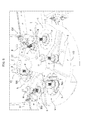
- FIG. 1A The annexed drawings refer to one embodiment of the invention designed for operating on components P of costant-velocity joints (see Figure 1A ) having a metal body including a stem G terminating in a bell-shaped portion B having an inner surface S.
- the apparatus according to the invention is designed to carry out induction heating both of the inner surface S of the bell-shaped portion B and of a portion of the surface of the stem G.
- reference number 1 generally designates a platform constituting the heart of the apparatus in the embodiment illustrated herein.
- platform 1 is fixed, even though the possibility is not excluded that it can be arranged in various rotated positions.
- the platform 1 has a series of sectors 2, 3, 4, 5, 6, 7 defined on which are subsequent operating stations I/O, I, II, III, IV, V arranged along a circumferential path, through which the components to be treated are displaced in sequence.
- sector 2 defines a station I/O used both for inlet of the components to be subjected to treatment and for outlet of the components that have been treated, as will be illustrated in greater detail in what follows. It is, however, evident that the inlet and outlet stations could also be defined on two different sectors of the platform 1.
- Figure 1 Illustrated in Figure 1 is a component P set in position in the inlet/outlet station I/O.
- Figure 1 does not show the components P that are located in the various operating stations nor the means provided in the apparatus according to the invention for carrying the components through the various operating stations along the circumferential path defined by platform 1.
- first induction-heating station I designed to carry out induction hardening of the inner surface S of the bell-shaped portion B of component P.
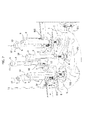
- station I is defined within a cylindrical cavity 300 that traverses the platform 1 vertically from its bottom surface to its top surface. Within said cavity 300 an inductor device ID1 projects from below.
- the inductor device ID1 is made in any way known to the persons skilled in the art.
- the inductor device ID1 comprises a member made of copper having the function of a coil, which is traversed by an alternating current.
- the inductor device ID1 is carried in a cantilever fashion by two BUS bars 301 projecting horizontally from a heating head 302 mounted on a pair of slides (not illustrated) that enable both vertical and horizontal movement thereof.
- the inductor device is configured for being immediately adjacent to the inner surface S of the component P positioned in the station.
- the bell-shaped portion B is cooled in the very same station by a shower constituted by a plurality of jets of cooling fluid (for example, liquid or air) coming out of holes or nozzles prearranged on the circumferential wall of cavity 300.
- a shower of cooling fluid constituted by jets from nozzles associated to the structure of the inductor ID1, according to a technique known per se.
- the component P that is located in the induction-heating station I is rotated about its axis during the heating step so as to bring the entire inner surface S of the bell-shaped portion B to cooperate with the inductor device ID1.
- This is obtained due to that the component P is gripped at the top end of the stem G by a gripping head H, constituted by a self-centering chuck of any known type (for example, of the type used in machine tools) carried at the bottom end of a motorized spindle, according to what will be described in greater detail in the following.
- the component is set in rotation about its axis also during the cooling step.
- a second induction-heating station II designed to execute hardening of a portion of the stem G of the component P.
- the station is defined by a cylindrical cavity 400 that extends from the top surface of the platform 4, but in this case the cavity 400 terminates in a bottom wall 401.
- an inductor device ID2 carried in a cantilever fashion by two BUS bars 402 and shaped and prearranged so as to surround partially the stem G of the component P that is located in the station II, in strict proximity thereto.
- the bus bars 402 project horizontally from a heating head 403 mounted on a pair of slides (not illustrated) that enable both vertical and horizontal movement thereof.
- the component P is set in rotation about its axis by means of the gripping head H associated thereto (see also Figure 3 ) so as to expose the entire surface of the stem G to the inductor device ID2.
- the circumferential wall of the cavity 400 has an array of holes or nozzles for directing jets of cooling fluid against the surface of the stem G following upon the heating step.
- the bottom wall of the cavity 400 is provided with nozzles for delivery of jets of cooling fluid so that the component P is subjected to spraying of cooling fluid both on its outer surface and on its inner surface S.
- each component P is brought into a station III, defined on the sector 5 of the fixed platform 1, in which a supplementary cooling operation is carried out on the component P.
- the supplementary cooling station III comprises a bowl 500 housed in a cavity of the platform 1, the circumferential wall of which is shaped so as to have planar portions 501 (see Figure 4 ) orthogonal to a tangential direction of the bowl 500.
- the wall portions 501 are provided with holes or nozzles 502 designed to direct cooling fluid jets in tangential directions.
- these tangential jets are distributed for a fair part of the height of the bowl 500.
- the latter is provided on its bottom with holes or nozzles 503 designed to direct cooling fluid jets upwards. In this way, within the bowl 500 there is created a turbulent circulation that improves the cooling efficiency.
- the body of the bowl 500 will be movable between a lowered, resting, position and a raised, operative, position, where it projects above the platform 1.
- a further induction-heating station IV on the sector 6 of the platform 1, defined immediately downstream of the supplementary cooling station III, is a further induction-heating station IV, where a further heating is carried out, with subsequent cooling of the surface of the stem G of the component P in order to obtain a tempering or a stress-relieving of the material of the stem G.
- the station IV is altogether similar to the station II described above.
- the station is defined within a cavity 600 provided with an array of holes 601 for delivery of jets of cooling fluid.
- an inductor device ID3 Associated to the station IV is an inductor device ID3, altogether similar to the inductor device ID2, carried in acantilever fashion by two BUS bars 602 projecting horizontally from a heating head 603 mounted on a pair of slides (not illustrated) that enable both vertical and horizontal sliding thereof.
- the component P is set in rotation about its axis during the heating step so as to offer the entire surface of the stem G to the inductor device ID3.
- a supplementary cooling station V is provided, altogether similar to the station III already described above.
- the station comprises a bowl 700 with a circumferential wall having portions 701 arranged orthogonal to a tangential direction in such a way that the holes 702 provided on the portions 701 issue jets of cooling liquid in a tangential direction, whilst vertical jets from beneath upwards come out of the nozzles 703 provided on the bottom wall of the bowl 700.
- the component P that has been cooled in the station V is then sent on, in the way that will be illustrated in what follows, to the outlet station, which in the example of embodiment illustrated coincides with the inlet station of the circumferential path defined on the platform 1, this inlet and outlet station being provided on the sector 2 of the platform 1 and being designated by the reference I/O.
- FIG. 6 is a perspective overall view of the platform 1 with the operating stations I/O, I, II, III, IV and V.
- a plurality of components P are illustrated, which are positioned, respectively, in the aforesaid operating stations and each of which is carried by a gripping head H.
- Each head H is, for example, made according to the configuration normally adopted for self-centring chucks of machine tools and can consequently be controlled between an opened configuration and a closed, gripping, configuration.
- the apparatus according to the invention is provided, in the case of the illustrated example, with six gripping heads H designed to grip and convey six components P simultaneously, each head always accompanying the respective component along the circumferential path through the various operating stations.
- the six gripping heads H are carried by as many motor-driven spindles, with vertical axis, which are rotatably mounted within respective spindle supporting units 8.
- Supported at the top of each spindle supporting unit 8 is an electric motor 9 for driving rotation of the respective spindle about the respective vertical axis 10.
- motor means of any other type may be used.
- each spindle supporting unit 8 is mounted in an adjustable position along a vertical axis Z2 within a clamp 11.
- the drawings show clamp 11 only diagrammatically and do not provide the constructional details thereof both because they can be made in any known way and because their elimination renders the drawings simpler and easier to understand.
- Adjustment of the vertical position along the vertical axis Z2 of each spindle supporting unit is made just once, during the step of calibration of the apparatus. In the case of a simpler embodiment, this adjustment is carried out manually by temporarily opening the clamp 11 that supports the spindle supporting unit.
- the position of each spindle supporting unit along the axis Z2 is controlled by an electric motor.
- Each support 11 is in turn carried by a slide 12 that is slidably mounted along a respective vertical axis Z1 on a corresponding guide 12A provided on the periphery of a central tower T.
- Tower T is rotatably supported on the platform 1, about the central vertical axis C of the platform 1, as may be seen more clearly in Figure 9 .
- the vertical tower T is supported in rotation on a central hub 13 projecting vertically from the centre of the fixed platform 1.
- Rotation of the tower T about the central axis C is driven by an electric motor (not visible in the drawings) connected by means of a transmission of any type to a transmission wheel (not visible in the drawings either) provided at the top end of the tower T.
- the vertical movements of the slides 12 provided on the periphery of the tower T are driven by driving means of any type.
- associated to the slides 12 there are respective nut-screws engaged by vertical screws V (see Figure 9 ) that project from the top end of the central tower T and that are driven in rotation by respective electric motors (not visible in the drawings) positioned at the top of the tower T.
- an electronic control unit E ( Figure 12 ) provided with a human-machine interface, which controls the motor for driving the tower T in rotation about the central axis C, the motors for driving the vertical displacement of the slides 12, and the motors 9 that drive the gripping heads H in rotation about their respective axes.
- the unit E is programmed to provide the cycle of operations described above on each component that is fed to the machine.
- a respective head H drops down thereon, due to the movement of the respective slide 12 along axis Z1.
- the head H grips the component, comes up again, and then takes the component to the first station I, where the head drops down to position the component within the cavity 300, with the inner surface S of the bell-shaped portion set adjacent to the inductor device ID1.
- the head H is then set in rotation via the respective motor 9 so as to cause the component to turn both during the step of induction heating and during the cooling step. Once these steps are through, the head goes up again, and then the tower T is made to turn to take the component to the next station. The aforesaid cycle of operations is repeated at each station.
- the six heads H provided on the tower T operate simultaneously so that the tower is set in rotation whenever all the heads H are ready to pass to the next station, once the cycle of operations in the station in which each head is located are through.
- the number of the operating stations, the configuration of each station may vary in order to enable on the one hand a high quality of the heating operation and on the other hand a short cycle time and a short retooling time.
- FIGS 10-12 are overall views of the apparatus according to the invention, which show the housing for containing the main components of the machine, which is designated as a whole by the reference D, as well as the conveyor devices 14, 15 for feeding the components P to the inlet and taking them away from the outlet.
- the conveyor devices 14, 15 are illustrated schematically in the drawings. Each of these devices may be constituted, for example, by a motor-driven conveyor belt of any known type.
- the conveyor belt 14 feeds a plurality of components P arranged in a line and adjacent to one another as far as an intermediate conveyor device 16, the speed of which is controlled in such a way as to bring about a spacing between the components P so as to feed just one component P in synchronism with the gripping head H that is in the inlet/outlet station I/O, immediately after it has released a component that has already been treated.
- the treated components are deposited at the inlet/outlet station I/O by issuing a command for opening of the gripping head H that is in that station at the end of the circumferential path defined by the platform 1.
- the treated component is thus released through a trap-door mechanism 17 onto an inclined plane 18 of a conveyor device 15 ( Figures 10 , 12 ) for discharge of the components.
- the apparatus according to the invention has an extremely simple, rational, and compact structure, with minimal overall dimensions in plan view. Notwithstanding the compact configuration, the apparatus is designed to get all the components that are to undergo heating to describe one and the same circumferential path through the same operating stations, to the advantage of uniformity of production quality. Provision of a rotatable tower T with peripheral spindles carrying the gripping heads H enables rationalization and acceleration of the entire operating cycle. Each gripping head always accompanies a respective component along the circumferential path through the various operating stations, unlike known devices, which envisage deposit and pick-up of the components in each station.
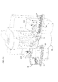
- Figures 13 and 14 illustrate the detail of a spindle supporting unit 8 of the apparatus according to the invention in a variant in which the clamp 11 is equipped with a flange 11 a rotatably mounted about a radial and horizontal axis Z3 on the respective slide 12.
- the spindle supporting unit 8 can be turned about the axis Z3 until it moves into the position where it is turned upside down, with the gripping head H facing upwards.
- Figure 14 shows this position, whilst Figure 13 shows an intermediate position during rotation through 180° of the spindle supporting unit 8.
- This optional additional feature may prove useful in applications in which the piece picked up from the line is to be brought into a position where it is turned upside down and faces upwards.
- Rotation of the vice 11 is preferably controlled by motor means of any type (not illustrated).
- Figure 15 shows a further optional feature, whereby the clamp 11 is also mounted movable along the axis Z3 with respect to the slide 12.
- the flange 11 a is equipped with a stem 11 b slidably mounted within the slide 12.
- this sliding movement of the vice 11 is preferably controlled by motor means of any type (not illustrated).
- This additional characteristic is useful in applications where there is required the possibility of varying the radial position of each gripping head H. This option may also be useful for preventing any interference between adjacent assemblies 8 when one of them is turned about the respective axis Z3.
- Figures 13-15 could be adopted also in an apparatus that does not envisage the vertically movable slides 12, i.e., in which the position of the axis Z3 is vertically fixed.
- the invention may be applied to components of any nature and configuration and not only to components of the type to which the example described herein refers.
- the configuration and number of the stations are chosen on the basis of the specific characteristics of the components and of the desired cycle time.
- the configuration of the inductor devices is chosen according to the conformation of the components to be treated.
- the stations have specific and independent supporting structures, the essential element being constituted by the fact that they are arranged along a circumferential path.
- the gripping heads are designed to set in continuous rotation the respective component during execution of an operation in a station of the apparatus.
- each head will be turned only through a limited angle in order to impart on the component a desired angular position, where the shape of the component requires the component to be positioned, for example with respect to an inductor device, in a predetermined angular position.
- no rotation of the gripping heads about their axes is required so that it is sufficient for the heads to be made to circulate by the rotatable tower in order to accompany the components along the circumferential path, without envisaging a rotation of the heads about their axes.
- the structure of the apparatus is consequently simplified, it not being necessary to envisage motor-driven spindles for carrying the heads, albeit maintaining the possibility of displacing each head vertically.
Landscapes
- Chemical & Material Sciences (AREA)
- Engineering & Computer Science (AREA)
- Physics & Mathematics (AREA)
- Thermal Sciences (AREA)
- Crystallography & Structural Chemistry (AREA)
- Mechanical Engineering (AREA)
- Materials Engineering (AREA)
- Metallurgy (AREA)
- Organic Chemistry (AREA)
- Electromagnetism (AREA)
- Heat Treatment Of Articles (AREA)
Priority Applications (1)
| Application Number | Priority Date | Filing Date | Title |
|---|---|---|---|
| EP14172714.9A EP2957530A1 (de) | 2014-06-17 | 2014-06-17 | Vorrichtung zum Induktionserwärmen von mechanischen Komponenten |
Applications Claiming Priority (1)
| Application Number | Priority Date | Filing Date | Title |
|---|---|---|---|
| EP14172714.9A EP2957530A1 (de) | 2014-06-17 | 2014-06-17 | Vorrichtung zum Induktionserwärmen von mechanischen Komponenten |
Publications (1)
| Publication Number | Publication Date |
|---|---|
| EP2957530A1 true EP2957530A1 (de) | 2015-12-23 |
Family
ID=51224673
Family Applications (1)
| Application Number | Title | Priority Date | Filing Date |
|---|---|---|---|
| EP14172714.9A Withdrawn EP2957530A1 (de) | 2014-06-17 | 2014-06-17 | Vorrichtung zum Induktionserwärmen von mechanischen Komponenten |
Country Status (1)
| Country | Link |
|---|---|
| EP (1) | EP2957530A1 (de) |
Cited By (2)
| Publication number | Priority date | Publication date | Assignee | Title |
|---|---|---|---|---|
| WO2017174054A1 (de) | 2016-04-07 | 2017-10-12 | EMAG GmbH & Co. KG | Härtemaschine |
| WO2019044763A1 (ja) * | 2017-08-28 | 2019-03-07 | Ntn株式会社 | 高周波熱処理設備 |
Citations (2)
| Publication number | Priority date | Publication date | Assignee | Title |
|---|---|---|---|---|
| GB1311026A (en) * | 1969-12-12 | 1973-03-21 | Park Ohio Industries Inc | Apparatus for inductively heating an elongated workpiece |
| US6089846A (en) * | 1996-05-22 | 2000-07-18 | Celes | Feed device for a pressure die-casting or injection machine |
-
2014
- 2014-06-17 EP EP14172714.9A patent/EP2957530A1/de not_active Withdrawn
Patent Citations (2)
| Publication number | Priority date | Publication date | Assignee | Title |
|---|---|---|---|---|
| GB1311026A (en) * | 1969-12-12 | 1973-03-21 | Park Ohio Industries Inc | Apparatus for inductively heating an elongated workpiece |
| US6089846A (en) * | 1996-05-22 | 2000-07-18 | Celes | Feed device for a pressure die-casting or injection machine |
Cited By (5)
| Publication number | Priority date | Publication date | Assignee | Title |
|---|---|---|---|---|
| WO2017174054A1 (de) | 2016-04-07 | 2017-10-12 | EMAG GmbH & Co. KG | Härtemaschine |
| DE102016004177A1 (de) | 2016-04-07 | 2017-10-12 | EMAG GmbH & Co. KG | Härtemaschine |
| DE102016004177B4 (de) | 2016-04-07 | 2020-07-02 | EMAG GmbH & Co. KG | Härtemaschine |
| WO2019044763A1 (ja) * | 2017-08-28 | 2019-03-07 | Ntn株式会社 | 高周波熱処理設備 |
| JP2019039052A (ja) * | 2017-08-28 | 2019-03-14 | Ntn株式会社 | 高周波熱処理設備 |
Similar Documents
| Publication | Publication Date | Title |
|---|---|---|
| CN110607431B (zh) | 一种用于轮毂轴承淬火回火的自动线设备 | |
| CN107127083B (zh) | 用于物体表面处理的操作站和设备 | |
| JP6076483B2 (ja) | レーザー光線を用いて非回転対称な工作物を加工する方法および装置 | |
| CN103624672B (zh) | 智能化高精高效立式全自动珩磨机 | |
| CN218321541U (zh) | 一种轮子感应淬火装置 | |
| KR101659763B1 (ko) | 도장장치용 스핀들 지지체 | |
| CN101224995A (zh) | 一种施釉方法及其专用设备 | |
| CN107876613B (zh) | 一种联合管端处理与弯管处理的工件处理生产线及方法 | |
| CN108406316A (zh) | 一种螺母柱的自动化钻孔攻牙一体机 | |
| KR101659761B1 (ko) | 도장장치용 오버 헤드 스핀들 컨베이어 | |
| CN113953115A (zh) | 一种自动喷涂设备 | |
| CN114619550A (zh) | 一种青瓷加工用自动上釉喷涂设备及其工作方法 | |
| JP2002292502A (ja) | 機械加工システム及び機械加工システムを用いたワークピースの機械加工方法 | |
| CN117230285B (zh) | 一种淬火冷却一体式系统 | |
| JP6754496B2 (ja) | 成形のための装置および方法 | |
| JP5744435B2 (ja) | ワークの熱処理装置 | |
| CN208878992U (zh) | 刹车盘表面涂层固化加热装置及刹车盘表面涂层涂装设备 | |
| JP5712433B2 (ja) | ワークの熱処理装置 | |
| JP2778802B2 (ja) | 連続熱間鍛造方法及び装置 | |
| US20230210251A1 (en) | Apparatus and method for providing bristle products | |
| CN116618907A (zh) | 航空发动机叶片摩天轮焊接装置 | |
| US11163295B2 (en) | Continuous machining with robotic table tracking of fixture | |
| CN112677160A (zh) | 一种污水箱处理用智能机器人及其工作方法 | |
| EP2050537A1 (de) | Maschine und verfahren zur schleifung, polierung und satinierung von röhren und/oder metallplatten | |
| CN108906532A (zh) | 刹车盘表面涂层固化加热装置及刹车盘表面涂层涂装设备 |
Legal Events
| Date | Code | Title | Description |
|---|---|---|---|
| PUAI | Public reference made under article 153(3) epc to a published international application that has entered the european phase |
Free format text: ORIGINAL CODE: 0009012 |
|
| AK | Designated contracting states |
Kind code of ref document: A1 Designated state(s): AL AT BE BG CH CY CZ DE DK EE ES FI FR GB GR HR HU IE IS IT LI LT LU LV MC MK MT NL NO PL PT RO RS SE SI SK SM TR |
|
| AX | Request for extension of the european patent |
Extension state: BA ME |
|
| STAA | Information on the status of an ep patent application or granted ep patent |
Free format text: STATUS: THE APPLICATION IS DEEMED TO BE WITHDRAWN |
|
| 18D | Application deemed to be withdrawn |
Effective date: 20160624 |