EP2957700B1 - Opérateur de fenêtre de toit - Google Patents
Opérateur de fenêtre de toit Download PDFInfo
- Publication number
- EP2957700B1 EP2957700B1 EP14166314.6A EP14166314A EP2957700B1 EP 2957700 B1 EP2957700 B1 EP 2957700B1 EP 14166314 A EP14166314 A EP 14166314A EP 2957700 B1 EP2957700 B1 EP 2957700B1
- Authority
- EP
- European Patent Office
- Prior art keywords
- winding drum
- operating
- drive unit
- sash
- drive shaft
- Prior art date
- Legal status (The legal status is an assumption and is not a legal conclusion. Google has not performed a legal analysis and makes no representation as to the accuracy of the status listed.)
- Active
Links
Images


Classifications
-
- E—FIXED CONSTRUCTIONS
- E05—LOCKS; KEYS; WINDOW OR DOOR FITTINGS; SAFES
- E05F—DEVICES FOR MOVING WINGS INTO OPEN OR CLOSED POSITION; CHECKS FOR WINGS; WING FITTINGS NOT OTHERWISE PROVIDED FOR, CONCERNED WITH THE FUNCTIONING OF THE WING
- E05F1/00—Closers or openers for wings, not otherwise provided for in this subclass
- E05F1/002—Closers or openers for wings, not otherwise provided for in this subclass controlled by automatically acting means
- E05F1/008—Closers or openers for wings, not otherwise provided for in this subclass controlled by automatically acting means by time control
-
- E—FIXED CONSTRUCTIONS
- E05—LOCKS; KEYS; WINDOW OR DOOR FITTINGS; SAFES
- E05F—DEVICES FOR MOVING WINGS INTO OPEN OR CLOSED POSITION; CHECKS FOR WINGS; WING FITTINGS NOT OTHERWISE PROVIDED FOR, CONCERNED WITH THE FUNCTIONING OF THE WING
- E05F1/00—Closers or openers for wings, not otherwise provided for in this subclass
- E05F1/002—Closers or openers for wings, not otherwise provided for in this subclass controlled by automatically acting means
- E05F1/004—Closers or openers for wings, not otherwise provided for in this subclass controlled by automatically acting means by thermostats, rain, wind or noise
-
- E—FIXED CONSTRUCTIONS
- E05—LOCKS; KEYS; WINDOW OR DOOR FITTINGS; SAFES
- E05F—DEVICES FOR MOVING WINGS INTO OPEN OR CLOSED POSITION; CHECKS FOR WINGS; WING FITTINGS NOT OTHERWISE PROVIDED FOR, CONCERNED WITH THE FUNCTIONING OF THE WING
- E05F1/00—Closers or openers for wings, not otherwise provided for in this subclass
- E05F1/002—Closers or openers for wings, not otherwise provided for in this subclass controlled by automatically acting means
- E05F1/006—Closers or openers for wings, not otherwise provided for in this subclass controlled by automatically acting means by emergency conditions, e.g. fire
-
- E—FIXED CONSTRUCTIONS
- E05—LOCKS; KEYS; WINDOW OR DOOR FITTINGS; SAFES
- E05F—DEVICES FOR MOVING WINGS INTO OPEN OR CLOSED POSITION; CHECKS FOR WINGS; WING FITTINGS NOT OTHERWISE PROVIDED FOR, CONCERNED WITH THE FUNCTIONING OF THE WING
- E05F15/00—Power-operated mechanisms for wings
- E05F15/60—Power-operated mechanisms for wings using electrical actuators
- E05F15/603—Power-operated mechanisms for wings using electrical actuators using rotary electromotors
- E05F15/611—Power-operated mechanisms for wings using electrical actuators using rotary electromotors for swinging wings
- E05F15/627—Power-operated mechanisms for wings using electrical actuators using rotary electromotors for swinging wings operated by flexible elongated pulling elements, e.g. belts, chains or cables
-
- E—FIXED CONSTRUCTIONS
- E05—LOCKS; KEYS; WINDOW OR DOOR FITTINGS; SAFES
- E05F—DEVICES FOR MOVING WINGS INTO OPEN OR CLOSED POSITION; CHECKS FOR WINGS; WING FITTINGS NOT OTHERWISE PROVIDED FOR, CONCERNED WITH THE FUNCTIONING OF THE WING
- E05F15/00—Power-operated mechanisms for wings
- E05F15/70—Power-operated mechanisms for wings with automatic actuation
- E05F15/71—Power-operated mechanisms for wings with automatic actuation responsive to temperature changes, rain, wind or noise
-
- E—FIXED CONSTRUCTIONS
- E05—LOCKS; KEYS; WINDOW OR DOOR FITTINGS; SAFES
- E05F—DEVICES FOR MOVING WINGS INTO OPEN OR CLOSED POSITION; CHECKS FOR WINGS; WING FITTINGS NOT OTHERWISE PROVIDED FOR, CONCERNED WITH THE FUNCTIONING OF THE WING
- E05F15/00—Power-operated mechanisms for wings
- E05F15/70—Power-operated mechanisms for wings with automatic actuation
- E05F15/72—Power-operated mechanisms for wings with automatic actuation responsive to emergency conditions, e.g. fire
-
- E—FIXED CONSTRUCTIONS
- E05—LOCKS; KEYS; WINDOW OR DOOR FITTINGS; SAFES
- E05F—DEVICES FOR MOVING WINGS INTO OPEN OR CLOSED POSITION; CHECKS FOR WINGS; WING FITTINGS NOT OTHERWISE PROVIDED FOR, CONCERNED WITH THE FUNCTIONING OF THE WING
- E05F15/00—Power-operated mechanisms for wings
- E05F15/70—Power-operated mechanisms for wings with automatic actuation
- E05F15/79—Power-operated mechanisms for wings with automatic actuation using time control
-
- E—FIXED CONSTRUCTIONS
- E05—LOCKS; KEYS; WINDOW OR DOOR FITTINGS; SAFES
- E05Y—INDEXING SCHEME ASSOCIATED WITH SUBCLASSES E05D AND E05F, RELATING TO CONSTRUCTION ELEMENTS, ELECTRIC CONTROL, POWER SUPPLY, POWER SIGNAL OR TRANSMISSION, USER INTERFACES, MOUNTING OR COUPLING, DETAILS, ACCESSORIES, AUXILIARY OPERATIONS NOT OTHERWISE PROVIDED FOR, APPLICATION THEREOF
- E05Y2201/00—Constructional elements; Accessories therefor
- E05Y2201/20—Brakes; Disengaging means; Holders; Stops; Valves; Accessories therefor
- E05Y2201/214—Disengaging means
- E05Y2201/216—Clutches
-
- E—FIXED CONSTRUCTIONS
- E05—LOCKS; KEYS; WINDOW OR DOOR FITTINGS; SAFES
- E05Y—INDEXING SCHEME ASSOCIATED WITH SUBCLASSES E05D AND E05F, RELATING TO CONSTRUCTION ELEMENTS, ELECTRIC CONTROL, POWER SUPPLY, POWER SIGNAL OR TRANSMISSION, USER INTERFACES, MOUNTING OR COUPLING, DETAILS, ACCESSORIES, AUXILIARY OPERATIONS NOT OTHERWISE PROVIDED FOR, APPLICATION THEREOF
- E05Y2900/00—Application of doors, windows, wings or fittings thereof
- E05Y2900/10—Application of doors, windows, wings or fittings thereof for buildings or parts thereof
- E05Y2900/13—Type of wing
- E05Y2900/148—Windows
- E05Y2900/152—Roof windows
Definitions
- the present invention relates to a roof window operating arrangement for closing of a roof window comprising a sash and a frame, in which an operator housing is adapted to be connected to one of the frame or sash and from where an operating element extends and is adapted to releasably connect to the corresponding opposite sash or frame, in which the operator housing is provided with a drive unit comprising an electric motor connected to a drive shaft, the drive shaft being further arranged with a winding drum, the winding drum being actuated by one end of a spring, the opposite end of the spring being connected to a fixed point, such as the operator housing, where the winding drum is arranged to wind up the operating element.
- Windows of this kind are often installed out of reach high in the ceiling of a roof, which makes them difficult to manually open or close. They are therefore often equipped with an electrically driven operating arrangement, with which an opening or closing of the roof window may be controlled by for example a remote control handled by a user. Such roof window operating arrangements are therefore often of a somewhat complex structure being equipped with for example power demanding drive units, which controls a connection element connecting the sash and frame.
- FIG. 1 856 358 B1 An example of such a roof window comprising an electrically driven operating arrangement can be found in Applicant's European patent EP 1 856 358 B1 .
- This document discloses an operating arrangement with an operator housing connected to a frame and an operating element extending from the frame to the sash, to which it releasably connects with a part thereof.
- the operator housing is provided with an operator chain, working as the operating element and being operated by the operator housing when closing and opening the window.
- This kind of electrically driven operating arrangement has a fairly complex coupling between the sash and frame due to the forces exerted during operation thereof.
- the releasable coupling is in more detail provided by a male part attached to an end of the chain, which male part connects with a female part of the window frame.
- the connection between the male and female part may be released by exerting a certain amount of force to overcome a frictional and/or elastic resistance provided by the connection.
- the components of the releasable connection may be hard to reach and the decoupling of the sash and frame hard to manually handle. Even if provided in reach in the ceiling of a roof such electrically driven operating arrangements are often expensive to produce and require a certain power in order to be operated. Moreover, they may not be manually overruled, for example such as to be closed by hand, since they are electrically driven and thereby self locking.
- EP 2 508 704 A2 including a gear in which decoupling of cogwheels from the gear is carried out by pulling a cord
- DE 20 2004 008762 U1 describing a closing mechanism with a pulling cord to be hung on a snaphook when cleaning the window.
- a roof window operating arrangement which in an active state of the drive unit rotates the winding drum in a first direction, whereby the operating element is wound up.
- the force created by the drive unit in the active state is big enough to rotate the winding drum, such that the operator element not only winds up on the winding drum but also closes the roof window automatically.
- the inactive state of the operating arrangement provides the winding drum with a free-wheeled mechanism in a first and a second direction, such that the operating element of the operating arrangement can be controlled manually, that is for example be unwound without substantially resistance.
- This type of operating arrangement is not only influenced by the force created by the drive unit, but also actuated by the force of a spring. With this spring force an automated winding up of the operating element, when the drive unit is in an inactive state, is achieved.
- a two-part control mechanism which is influenced by the force of the drive unit or the spring, such that an operating arrangement is provided which in an active as well as in an inactive state is able to automatic wind up the operating element, while at the same time preserving low resistance when unwinding of the same.
- the two-part control mechanism of the operating arrangement may thereby be activated by a user handling a window of the kind mentioned in the introduction. When a user opens the window the operating element is wound out from the operator housing, i.e. the winding drum, where it extends from a sash or frame to the corresponding opposite frame or sash.
- the operating element may manually be released from a part of the sash, whereby the force created in the spring, from the unwinding of the operating element, is biased such as to automatically wind up the operating element.
- the operating element is not a disturbing factor hanging freely from the operator housing when released from a part of the sash.
- the arrangement of the drive unit creates a power strong enough to wind up the operating element whereby the window is closed.
- the operating arrangement can be manually handled during opening as well as closing of the window, while preserving the automation of the roof window during for example closure thereof.
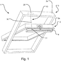
- Fig. 1 a schematic view of a window 1 provided with an operating arrangement 10 according to an embodiment of the invention is shown.
- the window 1 comprises a sash 2 and a frame 3, wherein the sash 2 pivots substantially about the centre of the frame 3 during opening thereof.
- the frame 3 has, in a manner known per se, a bottom member, a top member, and two side members, which together define a frame plane, and the sash 2 has, in a corresponding manner, a bottom member, a top member, and two side members encasing a pane (not shown) and defining a sash plane. Only the top member 2a of the sash 2 and the top member 3a of the frame 3 will be referred to in more detail.
- the window may for instance be a roof window to be built into an inclined roof surface (not shown).
- the window 1 is provided with an operating arrangement 10, for closing of the window 1.
- the operating arrangement 10 is provided with an operator housing 20 which is adapted to be connected to one of the frame 3 or sash 2 from where an operating element 30 extends and is adapted to releasably connect to the corresponding opposite sash 2 or frame 3.
- this arrangement causes the operating element 30 to extend in a direction of pivotal movement of the sash 2, during opening of the window 1, as for example shown in Fig 7 .
- the operator housing 20 is connected to a top member 3a of the frame 3, from where the operating element 30 extends and is adapted to releasably connect to a part of the top member 2a of the sash 2.
- the releasable connection between the sash 2 and frame 3 is adapted to be disconnected to manually handle the window 1 for example to a pivoted position, which is not limited to a certain degree of pivoting movement, as for example shown in Fig. 8 .
- the operating element 30 could be a cord or a wire, both of which types of material are cheap in production and easy to install. Furthermore the use of a cord or wire requires less power to control compared to for example the prior art use of chains.
- the operating element 30 is releasably connected to a holding element 31, provided on a part of the sash 2.
- This connection of the operating element 30 to the holding element 31 provides an easy installation as well as handling of the releasable connection.
- the operating element 30 is, in the embodiments shown in Figs 3 and 5 , provided with an engagement element 132, 232, which engages with the holding element 131, 231.
- the specific part of the sash to which the holding element 31 is provided is on an operating flap 4.
- Such operating flap 4 is often provided on the sash 2 in order to create a user-friendly handling of the window.
- the operating element 30 is connected to a holding element 31 provided in connection with the operating flap 4 connected to the sash 2.
- opening of the window 1 by a user gripping the operating flap 4 causes the operating element 30 to unwind from the operator housing 20 and extend in a direction following the movement of the operating flap 4.
- a closure of the window 1 and/or flap 4 itself causes the operating element 30 to wind up in the operator housing 20, creating a secure locking thereof, as illustrated in Fig 7(b) and (c) .
- Figs 1 , 7 and 8 only show an embodiment comprising an operating flap 4, in which a holding element 31 is arranged, the invention should not be limited thereto.
- the holding element could be provided directly on a part of the sash, such as a groove in the sash or for example the holding element could be a bracket fastened on the sash itself.
- This simple operating arrangement provides an improved operating arrangement which is easier to install in a window.
- the operator housing of the operating arrangement could simply be mounted on the frame by means of screws or the like, and the holding element could likewise simply be screwed into the operation flap of the sash or the sash itself.
- the releasable connection between the sash 2 and frame 3 is in a stepwise manner illustrated in Fig. 8(a) and (b) .
- a user may grip the operating flap 4 in order to open the window 1.
- the user may decouple the operating element 30 from the sash 2, as illustrated in Fig. 8(a) , whereby the operator housing 20 automatically winds up the operating element 30 as seen in Fig. 8(b) .
- the operating element 30 is not a disturbing element hanging freely, while for example cleaning the window.
- FIG. 2 shows a schematic view of an operator housing 20, where the operator housing 20 is provided with a drive unit 21 connected to a drive shaft 22, the drive shaft 22 being further arranged with a winding drum 23, where the winding drum 23 is actuated by one end of a spring 24, the opposite end of the spring being connected to a fixation point 25 such as the operator housing 20.
- the winding drum 23 is arranged to wind up the operating element 30, such that when in an active state of the drive unit 21, the drive shaft 22 rotates the winding drum 23 in a first direction winding up the operating element 30, and when in an inactive state the winding drum 23 is free-wheeled in a first and a second direction.
- the winding drum 23 may be rotated in a first and second direction without substantially resistance.
- the operating element 30 may therefore be unwound from the winding drum 23 without substantially resistance, such that it is easily handled during operation of the window.
- the operator may have feedback sensors to enable the operator to transmit the window position information i.e. whether the window is open or closed and secured.
- the winding drum 23 may furthermore be actuated by the force of the spring 24, which in the embodiment shown is a wrap spring 24 creating an automatic winding up of the operating element 30.
- This automated winding up of the operating element 30 is especially advantageous when pivoting the window substantially 180 degrees during for example cleaning of the window, since no operating element 30 in this way freely hangs down from the window frame creating an unwanted disturbing object.
- Other possible springs such as a torsion spring or a coil spring could be other possible choices of springs used as a biasing force.
- the drive unit 21 comprises an electric motor connected to the drive shaft 22, such as a reduction gear axle.
- the winding up of the operating element 31 may be electrically driven, which creates enough power for the window to automatically windup the operating element 30 and close the window, without any manually control by a user.
- the reduction gear may be provided in order to control the winding up of the operating element 30, such that the operating flap 4 and/or the window is closed in a proper manner. That is the reduction gear drives the drive shaft, such that a smooth non rapid closure of the window is achieved.
- the operator housing 20 of Fig. 2 is in more detail provided with a one-way clutch system 40, which is arranged to engage with the winding drum 23 in an active state of the drive unit, and disengage with the winding drum in an inactive state thereof.
- a one-way clutch system 40 may be arranged in several different ways, where a few non-limiting examples will be explained in the following in connection with the invention.
- connection element 141 for example a pawl, such as to provide a one-way clutch 140 in the direction of rotation of the motor 121 winding up the operating element 130.
- the connection between the drive shaft 122 and connection element 141 is provided by a cover element 142, which is arranged with a slit 143, in which a protrusion 144 on the connection element 141 engages.
- the connection element 141 is furthermore connected to an anchor plate 145 which rotates with the drive shaft 122.
- the one-way clutch 140 is configured to engage the drive shaft 122 with the winding drum 123 in the active state of the motor 121 and disengage the drive shaft 122 from the winding drum 123 in the inactive state.
- the engagement and disengagement between the winding drum 123 and the drive shaft 122 is obtained by the connection element 141 being forced, through the connection of the protrusion 144 in the slit 143, to engage with one end 148 in a groove 146 in the winding drum 123, best illustrated in Fig. 4 , whereby a coupling between the winding drum 123 and drive shaft 122 is obtained, when the drive unit 121 is in an active state.
- the winding drum 123 In an inactive state of the drive unit 121, the winding drum 123 is able to be rotated substantially without any resistance, due to the free-wheeled motion provided by the one-way clutch system 140.
- the end 148 of the connection element 141 decouples from the groove 146 in the winding drum 123, such that a free-wheeled motion is obtained.
- the rotation of the winding drum 123 influences the spring 124, which is tensioned such that it in an inactive state is able to wind up the operating element 130 automatically when this is released from the holding element 131.
- the drive unit 121 is arranged at an end opposite of the one-way clutch system 140.
- the spring 124 is in one end connected to a part of the housing 125 and in the other to the winding drum 123.
- the drive unit 221 is provided in the same end of the drive shaft 222 as the one-way clutch system 240, as shown in the operator housing 220 of Fig. 5 .
- the drive shaft 222 is connected to a part of the housing through a fixation point and in the other end the drive unit 221 is connected to the one-way clutch system 240.
- the one-way clutch system 240 of this embodiment is provided by a hub 241 which in an active state of the drive unit 221 is rotated, whereby the hub 241 engages with rollers 246 attached to the winding drum 223.
- This engagement creates a locking between the hub 241 and winding drum 223, such that the winding drum 223 is rotated in the direction of rotation of the drive unit 221, where the drive unit 221 may be comprised by an electrical motor. Furthermore when in an inactive state of the drive unit 221, a counter clock wise rotation of the winding drum 223 is able to disengage the roller 246 from the hub 241, such that a free-wheeled motion of the winding drum 223 is obtained, in a manner as explained in the previous embodiment.
- the winding drum 223 may as described in the previous embodiment also be influenced by the tensioning of the spring 224 connected through fixation point 225 to the housing, such that an automatic winding up of the operating element 230 is obtained when the operating element 230 is released from the holding element 231.
- the operating arrangement 10 may be provided with a control unit (not shown), which detects an opening of the window and further closes the window after a specified time interval. In case the window is opened and not manually closed again, the control unit thereby automatically closes the window. This is for example an advantageous if leaving a house without remembering to close the windows, which then automatically closes after a specified set time interval.
- the control unit may therefore be equipped with a timer, which is set to close the window after a given time. This time could for example in a given interval in minutes or hours, preferably 2-30 minutes.
- the time interval in which the window is set to close may be adjusted by a button provided on the operator housing. In this way the timer may be easily set by user.
- the time for closing the window may for example be indicated by the amount the window is opened, so a small opening equals that the window is to be closed soon i.e. 3 minutes, and a large opening equals the window is to be closed later i.e. 30 minutes.
- the operating arrangement could furthermore be equipped with a rain sensor.
- the rain sensor being able to detect rain drops falling on the window, causing the control unit to be activated to close the window automatically.
- the operating arrangement may be activated and close the window based on a signal from a remote or a mobile phone for example when a user leaves the building. And the operating arrangement may provide window status information so a user can verify whether the window is closed or open.
- the operating element may preferably automatically join with the holding element when the window is moved to a closed position, such that a secured automatic closing of the window is obtained.
- the operating arrangement could be battery powered.
- the operating arrangement could be equipped with a battery power sensor, which would create an alarm when the battery runs out of power and should be changed.
- roof windows often employ friction hinges that allow the user to position the window in an open position and the hinges will keep the window in that position.
- the disclosed operator is well suited for such windows.
Landscapes
- Business, Economics & Management (AREA)
- Emergency Management (AREA)
- Power-Operated Mechanisms For Wings (AREA)
Claims (14)
- Agencement d'actionnement (10) de fenêtre de toit pour la fermeture d'une fenêtre de toit (1) comprenant un châssis (2) et un cadre (3), l'agencement d'actionnement comprenant un boîtier de commande (120) qui est conçu pour être relié à l'un du cadre (3) ou du châssis (2) et à partir duquel un élément d'actionnement (130) s'étend et est conçu pour être relié de manière amovible au châssis (2) ou au cadre (3) opposé correspondant, le boîtier de commande (120) étant pourvu d'une unité d'entraînement (121) comprenant un moteur électrique relié à un arbre d'entraînement (122) de l'agencement d'actionnement, l'arbre d'entraînement (122) étant en outre conçu avec un tambour d'enroulement (123), le tambour d'enroulement (123) étant actionné par une extrémité d'un ressort (124), l'extrémité opposée du ressort étant reliée à un point fixe (125) tel que le boîtier de commande (120), le tambour d'enroulement (123) étant conçu pour enrouler l'élément d'actionnement (130), caractérisé en ce que l'agencement d'actionnement comprend un système d'embrayage unidirectionnel (140) qui est conçu pour mettre en prise l'unité d'entraînement (121) avec le tambour d'enroulement (23) dans un état actif et séparer l'unité d'entraînement (121) du tambour d'enroulement dans un état inactif, le système d'embrayage unidirectionnel (140) étant fourni par l'arbre d'entraînement (122) relié au tambour d'enroulement (123) par un élément de liaison (141), de sorte à fournir un embrayage unidirectionnel (140) dans la direction de rotation du moteur (121) enroulant l'élément d'actionnement (130), la liaison entre l'arbre d'entraînement (122) et l'élément de liaison (141) étant fournie par un élément couvercle (142), qui est conçu avec une fente (143), dans laquelle une saillie (144) sur l'élément de liaison (141) vient en prise, l'élément de liaison (141) étant en outre relié à une plaque d'ancrage (145) qui tourne avec l'arbre d'entraînement (122), et en ce que l'embrayage unidirectionnel (140) est conçu pour venir en prise l'arbre d'entraînement (122) avec le tambour d'enroulement (123) dans l'état actif de l'unité d'entraînement (121) et séparer l'arbre d'entraînement (122) du tambour d'enroulement (123) dans l'état inactif de l'unité d'entraînement (121), la mise en prise et la séparation entre le tambour d'enroulement (123) et l'arbre d'entraînement (122) étant obtenues par le fait que l'élément de liaison (141) est forcé, par la liaison de la saillie (144) dans la fente (143), à venir en prise avec une extrémité (148) dans une rainure (146) dans le tambour d'enroulement (123), et en ce que à l'état actif de l'unité d'entraînement (121), l'arbre d'entraînement (122) fait tourner le tambour d'enroulement (123) dans une première direction enroulant l'élément d'actionnement (130), et à l'état inactif, le tambour d'enroulement (123) tourne librement dans une première et une seconde direction, et en ce que le tambour d'enroulement (123) est en outre influencé par le fait que la force du ressort (124) crée un enroulement automatique de l'élément d'actionnement (130) lorsque l'unité d'entraînement est à l'état inactif.
- Agencement d'actionnement (10) de fenêtre de toit pour la fermeture d'une fenêtre de toit (1) comprenant un châssis (2) et un cadre (3), l'agencement d'actionnement comprenant un boîtier de commande (220) qui est conçu pour être relié à l'un du cadre (3) ou du châssis (2) et à partir duquel un élément d'actionnement (230) s'étend et est conçu pour être relié de manière amovible au châssis (2) ou au cadre (3) opposé correspondant, le boîtier de commande (220) étant pourvu d'une unité d'entraînement (221) comprenant un moteur électrique relié à un arbre d'entraînement (222) de l'agencement d'actionnement, l'arbre d'entraînement (222) étant en outre conçu avec un tambour d'enroulement (223), le tambour d'enroulement (223) étant actionné par une extrémité d'un ressort (224), l'extrémité opposée du ressort étant reliée à un point fixe (225) tel que le boîtier de commande (220), le tambour d'enroulement (223) étant conçu pour enrouler l'élément d'actionnement (230), caractérisé en ce que l'agencement d'actionnement comprend un système d'embrayage unidirectionnel (240) qui est conçu pour mettre en prise l'unité d'entraînement (221) avec le tambour d'enroulement (223) dans un état actif, et séparer l'unité d'entraînement (221) du tambour d'enroulement dans un état inactif, et en ce que l'unité d'entraînement (221) est fournie dans la même extrémité de l'arbre d'entraînement (222) que le système d'embrayage unidirectionnel (240), l'arbre d'entraînement (222) étant relié à une partie du logement par l'intermédiaire d'un point de fixation et dans l'autre extrémité l'unité d'entraînement (221) est reliée au système d'embrayage unidirectionnel (240),
et en ce que le système d'embrayage unidirectionnel (240) est fourni par un moyeu (241) qui, dans un état actif de l'unité d'entraînement (221), est mis en rotation, moyennant quoi le moyeu (241) vient en prise avec des rouleaux (246) fixés au tambour d'enroulement (223), créant un verrouillage entre le moyeu (241) et le tambour d'enroulement (223), de sorte que le tambour d'enroulement (223) tourne dans le sens de rotation de l'unité d'entraînement (221), et en ce que lorsque l'unité d'entraînement (221) est à l'état inactif, une rotation dans le sens inverse des aiguilles d'une montre du tambour d'enroulement (223) peut séparer le rouleau (246) du moyeu (241), de sorte qu'un mouvement en roue libre du tambour d'enroulement (223) soit obtenu, et en ce que lorsque l'unité d'entraînement (221) est à l'état actif, l'arbre d'entraînement (222) fait tourner le tambour d'enroulement (223) dans une première direction enroulant l'élément d'actionnement (230), et en ce que, à l'état inactif, le tambour d'enroulement (223) tourne librement dans une première et une seconde direction, et en ce que le tambour d'enroulement (223) est en outre influencé par le fait que la force du ressort (224) crée un enroulement automatique de l'élément d'actionnement (230) lorsque l'unité d'entraînement est dans un état inactif. - Fenêtre de toit comprenant un agencement d'actionnement (10) de fenêtre de toit selon la revendication 1 ou 2, le boîtier de commande (120 ; 220) étant relié au cadre (3) et l'élément d'actionnement (130 ; 230) étant relié de manière amovible au châssis (2) ou vice versa.
- Fenêtre de toit selon la revendication 3, l'élément d'actionnement (130 ; 230) étant relié de manière amovible à un élément de maintien (131 ; 231) tel qu'un support, fourni sur une partie du châssis (2).
- Fenêtre de toit selon la revendication 4, l'élément de maintien (131 ; 231) étant fourni en liaison avec un volet de manœuvre (4) relié au châssis (2).
- Fenêtre de toit selon l'une quelconque des revendications 4 à 5, l'élément d'actionnement (130 ; 230) étant conçu pour se joindre automatiquement à l'élément de maintien (131 ; 231) lorsque la fenêtre est déplacée vers une position fermée.
- Fenêtre de toit selon l'une quelconque des revendications 3 à 6, l'élément d'actionnement (130 ; 230) étant une corde ou un câble.
- Fenêtre de toit selon l'une quelconque des revendications 3 à 7, lorsqu'elle dépend de la revendication 1, l'unité d'entraînement (121 ; 221) comprenant un moteur électrique relié à l'arbre d'entraînement (122 ; 222), tel qu'un axe de réducteur.
- Fenêtre de toit selon l'une quelconque des revendications 3 à 8, l'agencement d'actionnement (10) étant muni d'une unité de commande, qui détecte une ouverture de la fenêtre et ferme la fenêtre après un intervalle de temps spécifié.
- Fenêtre de toit selon l'une quelconque des revendications 3 à 9, l'agencement d'actionnement (10) étant pourvu d'un capteur de pluie.
- Fenêtre de toit selon l'une quelconque des revendications 3 à 10, l'agencement opérationnel (10) étant à alimentation électrique.
- Fenêtre de toit selon l'une quelconque des revendications 3 à 11, l'agencement opérationnel (10) étant alimenté par batterie.
- Fenêtre de toit selon l'une quelconque des revendications 3 à 12 comprenant un châssis (2) pivotant et un cadre (3), le châssis (2) pivotant sensiblement autour du centre du cadre (3).
- Fenêtre de toit selon l'une quelconque des revendications 3 à 13, l'agencement d'actionnement (10) étant conçu pour fermer automatiquement la fenêtre (1) sans empêcher l'ouverture et la fermeture manuelles de la fenêtre (1).
Priority Applications (1)
| Application Number | Priority Date | Filing Date | Title |
|---|---|---|---|
| EP14166314.6A EP2957700B1 (fr) | 2014-04-29 | 2014-04-29 | Opérateur de fenêtre de toit |
Applications Claiming Priority (1)
| Application Number | Priority Date | Filing Date | Title |
|---|---|---|---|
| EP14166314.6A EP2957700B1 (fr) | 2014-04-29 | 2014-04-29 | Opérateur de fenêtre de toit |
Publications (2)
| Publication Number | Publication Date |
|---|---|
| EP2957700A1 EP2957700A1 (fr) | 2015-12-23 |
| EP2957700B1 true EP2957700B1 (fr) | 2021-08-11 |
Family
ID=50588570
Family Applications (1)
| Application Number | Title | Priority Date | Filing Date |
|---|---|---|---|
| EP14166314.6A Active EP2957700B1 (fr) | 2014-04-29 | 2014-04-29 | Opérateur de fenêtre de toit |
Country Status (1)
| Country | Link |
|---|---|
| EP (1) | EP2957700B1 (fr) |
Families Citing this family (9)
| Publication number | Priority date | Publication date | Assignee | Title |
|---|---|---|---|---|
| CN106677660B (zh) * | 2016-12-30 | 2018-03-23 | 深圳春沐源控股有限公司 | 旋转窗、控制窗户旋转的方法和装置 |
| CN107060567B (zh) * | 2017-06-21 | 2018-08-03 | 泉州齐美电子科技有限公司 | 一种基于气泵控制的下雨天自动关闭的窗户 |
| CN107060568B (zh) * | 2017-06-21 | 2018-02-16 | 广东皇派家居科技有限公司 | 一种基于水结冰触发的下雨天自动缓慢关闭的窗户 |
| EP3505696B1 (fr) | 2018-01-02 | 2024-03-27 | VKR Holding A/S | Fenêtre automatisée destinée à être installée sur un toit incliné |
| CN109538058A (zh) * | 2018-12-29 | 2019-03-29 | 苏州市富尔达科技股份有限公司 | 一种温感防火闭窗器 |
| CN109505480A (zh) * | 2018-12-29 | 2019-03-22 | 苏州市富尔达科技股份有限公司 | 一种自动温感闭窗器 |
| KR102076822B1 (ko) * | 2019-06-11 | 2020-02-12 | 서종용 | 자동 창문 개폐장치 |
| EP3770355B1 (fr) * | 2019-07-24 | 2022-06-29 | VKR Holding A/S | Agencement de fenêtre de toit comprenant un ensemble de fonctionnement manuel doté d'une pièce de commande intégrée |
| EP3770356B1 (fr) * | 2019-07-24 | 2022-06-29 | VKR Holding A/S | Kit de mise à niveau pour fenêtre de toit comprenant un ensemble de commande manuelle et agencement d'une fenêtre de toit comprenant un tel kit de mise à niveau |
Family Cites Families (3)
| Publication number | Priority date | Publication date | Assignee | Title |
|---|---|---|---|---|
| DE202004008762U1 (de) * | 2003-10-15 | 2004-09-30 | Merkle, Hans | Dachfensterschließer |
| PL1856358T3 (pl) | 2005-02-28 | 2009-12-31 | Vkr Holding As | Rozłączalne złącze |
| DE102011001156A1 (de) * | 2011-03-09 | 2012-09-13 | Hans Arnhold | Fensterschließer |
-
2014
- 2014-04-29 EP EP14166314.6A patent/EP2957700B1/fr active Active
Non-Patent Citations (1)
| Title |
|---|
| None * |
Also Published As
| Publication number | Publication date |
|---|---|
| EP2957700A1 (fr) | 2015-12-23 |
Similar Documents
| Publication | Publication Date | Title |
|---|---|---|
| EP2957700B1 (fr) | Opérateur de fenêtre de toit | |
| US10975619B2 (en) | Methods and apparatus to control architectural opening covering assemblies | |
| EP2719854B1 (fr) | Procédés et appareil pour commander un ensemble de recouvrement d'ouverture architecturale | |
| AU2011326816C1 (en) | Modular anti-reversible power spring apparatus and method | |
| EP2924209B1 (fr) | Fenêtre de toit ouvrant à verrouillage actif | |
| KR100706328B1 (ko) | 슬라이드 도어의 전동 개폐장치 | |
| KR101390363B1 (ko) | 미닫이 도어 장치 | |
| JP2010007408A (ja) | テンションスプリングカウンタウェイトを有するドアおよびその動作器 | |
| JP7040751B2 (ja) | 開閉装置 | |
| JP4829607B2 (ja) | 出窓の自動開閉装置 |
Legal Events
| Date | Code | Title | Description |
|---|---|---|---|
| PUAI | Public reference made under article 153(3) epc to a published international application that has entered the european phase |
Free format text: ORIGINAL CODE: 0009012 |
|
| AK | Designated contracting states |
Kind code of ref document: A1 Designated state(s): AL AT BE BG CH CY CZ DE DK EE ES FI FR GB GR HR HU IE IS IT LI LT LU LV MC MK MT NL NO PL PT RO RS SE SI SK SM TR |
|
| AX | Request for extension of the european patent |
Extension state: BA ME |
|
| 17P | Request for examination filed |
Effective date: 20151229 |
|
| RBV | Designated contracting states (corrected) |
Designated state(s): AL AT BE BG CH CY CZ DE DK EE ES FI FR GB GR HR HU IE IS IT LI LT LU LV MC MK MT NL NO PL PT RO RS SE SI SK SM TR |
|
| STAA | Information on the status of an ep patent application or granted ep patent |
Free format text: STATUS: EXAMINATION IS IN PROGRESS |
|
| 17Q | First examination report despatched |
Effective date: 20190201 |
|
| GRAP | Despatch of communication of intention to grant a patent |
Free format text: ORIGINAL CODE: EPIDOSNIGR1 |
|
| STAA | Information on the status of an ep patent application or granted ep patent |
Free format text: STATUS: GRANT OF PATENT IS INTENDED |
|
| INTG | Intention to grant announced |
Effective date: 20210316 |
|
| GRAS | Grant fee paid |
Free format text: ORIGINAL CODE: EPIDOSNIGR3 |
|
| GRAA | (expected) grant |
Free format text: ORIGINAL CODE: 0009210 |
|
| STAA | Information on the status of an ep patent application or granted ep patent |
Free format text: STATUS: THE PATENT HAS BEEN GRANTED |
|
| AK | Designated contracting states |
Kind code of ref document: B1 Designated state(s): AL AT BE BG CH CY CZ DE DK EE ES FI FR GB GR HR HU IE IS IT LI LT LU LV MC MK MT NL NO PL PT RO RS SE SI SK SM TR |
|
| REG | Reference to a national code |
Ref country code: GB Ref legal event code: FG4D |
|
| REG | Reference to a national code |
Ref country code: CH Ref legal event code: EP |
|
| REG | Reference to a national code |
Ref country code: DE Ref legal event code: R096 Ref document number: 602014079327 Country of ref document: DE |
|
| REG | Reference to a national code |
Ref country code: IE Ref legal event code: FG4D Ref country code: AT Ref legal event code: REF Ref document number: 1419562 Country of ref document: AT Kind code of ref document: T Effective date: 20210915 |
|
| REG | Reference to a national code |
Ref country code: LT Ref legal event code: MG9D |
|
| REG | Reference to a national code |
Ref country code: NL Ref legal event code: MP Effective date: 20210811 |
|
| REG | Reference to a national code |
Ref country code: AT Ref legal event code: MK05 Ref document number: 1419562 Country of ref document: AT Kind code of ref document: T Effective date: 20210811 |
|
| PG25 | Lapsed in a contracting state [announced via postgrant information from national office to epo] |
Ref country code: RS Free format text: LAPSE BECAUSE OF FAILURE TO SUBMIT A TRANSLATION OF THE DESCRIPTION OR TO PAY THE FEE WITHIN THE PRESCRIBED TIME-LIMIT Effective date: 20210811 Ref country code: SE Free format text: LAPSE BECAUSE OF FAILURE TO SUBMIT A TRANSLATION OF THE DESCRIPTION OR TO PAY THE FEE WITHIN THE PRESCRIBED TIME-LIMIT Effective date: 20210811 Ref country code: HR Free format text: LAPSE BECAUSE OF FAILURE TO SUBMIT A TRANSLATION OF THE DESCRIPTION OR TO PAY THE FEE WITHIN THE PRESCRIBED TIME-LIMIT Effective date: 20210811 Ref country code: LT Free format text: LAPSE BECAUSE OF FAILURE TO SUBMIT A TRANSLATION OF THE DESCRIPTION OR TO PAY THE FEE WITHIN THE PRESCRIBED TIME-LIMIT Effective date: 20210811 Ref country code: AT Free format text: LAPSE BECAUSE OF FAILURE TO SUBMIT A TRANSLATION OF THE DESCRIPTION OR TO PAY THE FEE WITHIN THE PRESCRIBED TIME-LIMIT Effective date: 20210811 Ref country code: BG Free format text: LAPSE BECAUSE OF FAILURE TO SUBMIT A TRANSLATION OF THE DESCRIPTION OR TO PAY THE FEE WITHIN THE PRESCRIBED TIME-LIMIT Effective date: 20211111 Ref country code: PT Free format text: LAPSE BECAUSE OF FAILURE TO SUBMIT A TRANSLATION OF THE DESCRIPTION OR TO PAY THE FEE WITHIN THE PRESCRIBED TIME-LIMIT Effective date: 20211213 Ref country code: NO Free format text: LAPSE BECAUSE OF FAILURE TO SUBMIT A TRANSLATION OF THE DESCRIPTION OR TO PAY THE FEE WITHIN THE PRESCRIBED TIME-LIMIT Effective date: 20211111 Ref country code: ES Free format text: LAPSE BECAUSE OF FAILURE TO SUBMIT A TRANSLATION OF THE DESCRIPTION OR TO PAY THE FEE WITHIN THE PRESCRIBED TIME-LIMIT Effective date: 20210811 Ref country code: FI Free format text: LAPSE BECAUSE OF FAILURE TO SUBMIT A TRANSLATION OF THE DESCRIPTION OR TO PAY THE FEE WITHIN THE PRESCRIBED TIME-LIMIT Effective date: 20210811 |
|
| PG25 | Lapsed in a contracting state [announced via postgrant information from national office to epo] |
Ref country code: PL Free format text: LAPSE BECAUSE OF FAILURE TO SUBMIT A TRANSLATION OF THE DESCRIPTION OR TO PAY THE FEE WITHIN THE PRESCRIBED TIME-LIMIT Effective date: 20210811 Ref country code: LV Free format text: LAPSE BECAUSE OF FAILURE TO SUBMIT A TRANSLATION OF THE DESCRIPTION OR TO PAY THE FEE WITHIN THE PRESCRIBED TIME-LIMIT Effective date: 20210811 Ref country code: GR Free format text: LAPSE BECAUSE OF FAILURE TO SUBMIT A TRANSLATION OF THE DESCRIPTION OR TO PAY THE FEE WITHIN THE PRESCRIBED TIME-LIMIT Effective date: 20211112 |
|
| PG25 | Lapsed in a contracting state [announced via postgrant information from national office to epo] |
Ref country code: NL Free format text: LAPSE BECAUSE OF FAILURE TO SUBMIT A TRANSLATION OF THE DESCRIPTION OR TO PAY THE FEE WITHIN THE PRESCRIBED TIME-LIMIT Effective date: 20210811 |
|
| PG25 | Lapsed in a contracting state [announced via postgrant information from national office to epo] |
Ref country code: DK Free format text: LAPSE BECAUSE OF FAILURE TO SUBMIT A TRANSLATION OF THE DESCRIPTION OR TO PAY THE FEE WITHIN THE PRESCRIBED TIME-LIMIT Effective date: 20210811 |
|
| REG | Reference to a national code |
Ref country code: DE Ref legal event code: R097 Ref document number: 602014079327 Country of ref document: DE |
|
| PG25 | Lapsed in a contracting state [announced via postgrant information from national office to epo] |
Ref country code: SM Free format text: LAPSE BECAUSE OF FAILURE TO SUBMIT A TRANSLATION OF THE DESCRIPTION OR TO PAY THE FEE WITHIN THE PRESCRIBED TIME-LIMIT Effective date: 20210811 Ref country code: SK Free format text: LAPSE BECAUSE OF FAILURE TO SUBMIT A TRANSLATION OF THE DESCRIPTION OR TO PAY THE FEE WITHIN THE PRESCRIBED TIME-LIMIT Effective date: 20210811 Ref country code: RO Free format text: LAPSE BECAUSE OF FAILURE TO SUBMIT A TRANSLATION OF THE DESCRIPTION OR TO PAY THE FEE WITHIN THE PRESCRIBED TIME-LIMIT Effective date: 20210811 Ref country code: EE Free format text: LAPSE BECAUSE OF FAILURE TO SUBMIT A TRANSLATION OF THE DESCRIPTION OR TO PAY THE FEE WITHIN THE PRESCRIBED TIME-LIMIT Effective date: 20210811 Ref country code: CZ Free format text: LAPSE BECAUSE OF FAILURE TO SUBMIT A TRANSLATION OF THE DESCRIPTION OR TO PAY THE FEE WITHIN THE PRESCRIBED TIME-LIMIT Effective date: 20210811 Ref country code: AL Free format text: LAPSE BECAUSE OF FAILURE TO SUBMIT A TRANSLATION OF THE DESCRIPTION OR TO PAY THE FEE WITHIN THE PRESCRIBED TIME-LIMIT Effective date: 20210811 |
|
| PLBE | No opposition filed within time limit |
Free format text: ORIGINAL CODE: 0009261 |
|
| STAA | Information on the status of an ep patent application or granted ep patent |
Free format text: STATUS: NO OPPOSITION FILED WITHIN TIME LIMIT |
|
| 26N | No opposition filed |
Effective date: 20220512 |
|
| PG25 | Lapsed in a contracting state [announced via postgrant information from national office to epo] |
Ref country code: IT Free format text: LAPSE BECAUSE OF FAILURE TO SUBMIT A TRANSLATION OF THE DESCRIPTION OR TO PAY THE FEE WITHIN THE PRESCRIBED TIME-LIMIT Effective date: 20210811 |
|
| PG25 | Lapsed in a contracting state [announced via postgrant information from national office to epo] |
Ref country code: SI Free format text: LAPSE BECAUSE OF FAILURE TO SUBMIT A TRANSLATION OF THE DESCRIPTION OR TO PAY THE FEE WITHIN THE PRESCRIBED TIME-LIMIT Effective date: 20210811 |
|
| REG | Reference to a national code |
Ref country code: CH Ref legal event code: PL |
|
| GBPC | Gb: european patent ceased through non-payment of renewal fee |
Effective date: 20220429 |
|
| REG | Reference to a national code |
Ref country code: BE Ref legal event code: MM Effective date: 20220430 |
|
| PG25 | Lapsed in a contracting state [announced via postgrant information from national office to epo] |
Ref country code: MC Free format text: LAPSE BECAUSE OF FAILURE TO SUBMIT A TRANSLATION OF THE DESCRIPTION OR TO PAY THE FEE WITHIN THE PRESCRIBED TIME-LIMIT Effective date: 20210811 Ref country code: LU Free format text: LAPSE BECAUSE OF NON-PAYMENT OF DUE FEES Effective date: 20220429 Ref country code: LI Free format text: LAPSE BECAUSE OF NON-PAYMENT OF DUE FEES Effective date: 20220430 Ref country code: GB Free format text: LAPSE BECAUSE OF NON-PAYMENT OF DUE FEES Effective date: 20220429 Ref country code: CH Free format text: LAPSE BECAUSE OF NON-PAYMENT OF DUE FEES Effective date: 20220430 |
|
| PG25 | Lapsed in a contracting state [announced via postgrant information from national office to epo] |
Ref country code: BE Free format text: LAPSE BECAUSE OF NON-PAYMENT OF DUE FEES Effective date: 20220430 |
|
| PG25 | Lapsed in a contracting state [announced via postgrant information from national office to epo] |
Ref country code: IE Free format text: LAPSE BECAUSE OF NON-PAYMENT OF DUE FEES Effective date: 20220429 |
|
| PG25 | Lapsed in a contracting state [announced via postgrant information from national office to epo] |
Ref country code: HU Free format text: LAPSE BECAUSE OF FAILURE TO SUBMIT A TRANSLATION OF THE DESCRIPTION OR TO PAY THE FEE WITHIN THE PRESCRIBED TIME-LIMIT; INVALID AB INITIO Effective date: 20140429 |
|
| PG25 | Lapsed in a contracting state [announced via postgrant information from national office to epo] |
Ref country code: MK Free format text: LAPSE BECAUSE OF FAILURE TO SUBMIT A TRANSLATION OF THE DESCRIPTION OR TO PAY THE FEE WITHIN THE PRESCRIBED TIME-LIMIT Effective date: 20210811 Ref country code: CY Free format text: LAPSE BECAUSE OF FAILURE TO SUBMIT A TRANSLATION OF THE DESCRIPTION OR TO PAY THE FEE WITHIN THE PRESCRIBED TIME-LIMIT Effective date: 20210811 |
|
| PG25 | Lapsed in a contracting state [announced via postgrant information from national office to epo] |
Ref country code: TR Free format text: LAPSE BECAUSE OF FAILURE TO SUBMIT A TRANSLATION OF THE DESCRIPTION OR TO PAY THE FEE WITHIN THE PRESCRIBED TIME-LIMIT Effective date: 20210811 |
|
| PG25 | Lapsed in a contracting state [announced via postgrant information from national office to epo] |
Ref country code: MT Free format text: LAPSE BECAUSE OF FAILURE TO SUBMIT A TRANSLATION OF THE DESCRIPTION OR TO PAY THE FEE WITHIN THE PRESCRIBED TIME-LIMIT Effective date: 20210811 |
|
| PGFP | Annual fee paid to national office [announced via postgrant information from national office to epo] |
Ref country code: DE Payment date: 20250305 Year of fee payment: 12 |
|
| PGFP | Annual fee paid to national office [announced via postgrant information from national office to epo] |
Ref country code: FR Payment date: 20260323 Year of fee payment: 13 |