EP2957710B1 - Bohrkopf und Vorrichtung zum Herstellen einer Bohrung im Erdreich - Google Patents
Bohrkopf und Vorrichtung zum Herstellen einer Bohrung im Erdreich Download PDFInfo
- Publication number
- EP2957710B1 EP2957710B1 EP15160434.5A EP15160434A EP2957710B1 EP 2957710 B1 EP2957710 B1 EP 2957710B1 EP 15160434 A EP15160434 A EP 15160434A EP 2957710 B1 EP2957710 B1 EP 2957710B1
- Authority
- EP
- European Patent Office
- Prior art keywords
- drill head
- unit
- drill pipe
- drill
- contact arrangement
- Prior art date
- Legal status (The legal status is an assumption and is not a legal conclusion. Google has not performed a legal analysis and makes no representation as to the accuracy of the status listed.)
- Active
Links
Images




Classifications
-
- E—FIXED CONSTRUCTIONS
- E21—EARTH OR ROCK DRILLING; MINING
- E21B—EARTH OR ROCK DRILLING; OBTAINING OIL, GAS, WATER, SOLUBLE OR MELTABLE MATERIALS OR A SLURRY OF MINERALS FROM WELLS
- E21B4/00—Drives for drilling, used in the borehole
- E21B4/06—Down-hole impacting means, e.g. hammers
- E21B4/14—Fluid operated hammers
-
- E—FIXED CONSTRUCTIONS
- E21—EARTH OR ROCK DRILLING; MINING
- E21B—EARTH OR ROCK DRILLING; OBTAINING OIL, GAS, WATER, SOLUBLE OR MELTABLE MATERIALS OR A SLURRY OF MINERALS FROM WELLS
- E21B41/00—Equipment or details not covered by groups E21B15/00 - E21B40/00
- E21B41/0085—Adaptations of electric power generating means for use in boreholes
-
- E—FIXED CONSTRUCTIONS
- E21—EARTH OR ROCK DRILLING; MINING
- E21B—EARTH OR ROCK DRILLING; OBTAINING OIL, GAS, WATER, SOLUBLE OR MELTABLE MATERIALS OR A SLURRY OF MINERALS FROM WELLS
- E21B17/00—Drilling rods or pipes; Flexible drill strings; Kellies; Drill collars; Sucker rods; Cables; Casings; Tubings
- E21B17/02—Couplings; joints
- E21B17/028—Electrical or electro-magnetic connections
-
- E—FIXED CONSTRUCTIONS
- E21—EARTH OR ROCK DRILLING; MINING
- E21B—EARTH OR ROCK DRILLING; OBTAINING OIL, GAS, WATER, SOLUBLE OR MELTABLE MATERIALS OR A SLURRY OF MINERALS FROM WELLS
- E21B47/00—Survey of boreholes or wells
- E21B47/09—Locating or determining the position of objects in boreholes or wells, e.g. the position of an extending arm; Identifying the free or blocked portions of pipes
-
- E—FIXED CONSTRUCTIONS
- E21—EARTH OR ROCK DRILLING; MINING
- E21B—EARTH OR ROCK DRILLING; OBTAINING OIL, GAS, WATER, SOLUBLE OR MELTABLE MATERIALS OR A SLURRY OF MINERALS FROM WELLS
- E21B7/00—Special methods or apparatus for drilling
- E21B7/04—Directional drilling
- E21B7/046—Directional drilling horizontal drilling
-
- E—FIXED CONSTRUCTIONS
- E21—EARTH OR ROCK DRILLING; MINING
- E21B—EARTH OR ROCK DRILLING; OBTAINING OIL, GAS, WATER, SOLUBLE OR MELTABLE MATERIALS OR A SLURRY OF MINERALS FROM WELLS
- E21B7/00—Special methods or apparatus for drilling
- E21B7/04—Directional drilling
- E21B7/06—Deflecting the direction of boreholes
- E21B7/062—Deflecting the direction of boreholes the tool shaft rotating inside a non-rotating guide travelling with the shaft
Definitions
- the invention relates to a drill head for producing a hole in the ground, as it can be used for example in the so-called HDD (Horizontal Direction Drilling) drilling method.
- the drill head has a first unit which can be coupled to an inner linkage of the double pipe linkage and a second unit which can be coupled to an outer linkage of the double pipe linkage.
- the first unit is rotatable about an axis of rotation relative to the second unit which can be driven by means of the outer linkage with the aid of the inner linkage.
- the invention relates to a device for making a hole in the ground with such a drill head.
- pilot holes can be made between a starting point and a target point, which can then be enlarged with the aid of a second drill head and / or expander head.
- different drill heads are used, such as so-called rock clearers, for example, include a roller bit assembly or so-called Erdraketen or Imlochhoter through which a Schlagbohrvorgang takes place.
- Both the pilot bores and the widening of a bore with the aid of a widening tool can be liquid-assisted, in particular assisted by a bentonite flushing liquid.
- the rinsing liquid the excavated soil is discharged from the drilling channel.
- Pilot bores and flare holes can be made, for example, by means of a horizontal boring machine marketed by the assignee under the name "TERRA-JET". With the help of this drilling device horizontal directional controlled holes are possible.
- the drill head with the aid of which the pilot bore is generated, usually has a battery-operated locatable transmitter, so that its Position with the help of a portable locating device from the earth's surface is exactly determinable.
- the locating device must be located directly above the probe.
- the drilling depth must not be too large, so that the signal emitted by the probe penetrates to the earth's surface. Based on the determined position of the probe, the drill head can be controlled so that a desired course of the bore to be generated is achieved.
- the driven by the inner rod first unit may have means for the degradation of the soil.
- rock drill heads are known, which are equipped with three roller bits, which are each equipped with carbide pins. Such rock drilling heads are rotated at 30 to 300 revolutions per minute.
- the roller bits roll on the ground, in particular on the rock.
- the contact pressure between the hard metal pins of the roller chisel and the rock causes pieces of rock, so-called cuttings, to be broken off, which are then carried back from the drilling channel with the aid of the rinsing fluid.
- the bentonite flushing fluid simultaneously stabilizes the drilling channel.
- the central axis of the drill head is bent or kinked.
- the kink or bend is usually in the range between 1 ° and 3 °. If the drill head is driven by means of the inner linkage and simultaneously pressed the housing of the drill head without rotation in the soil, the drill head moves along its kink a curved bore. To drill straight ahead, the housing of the drill head must be rotated continuously slowly. Typically, the housing of the drill head is rotated at 10 to 30 revolutions per minute to make a straight bore.
- the controlled bore can also be alternatively produced to the provision of the bend or a kink in the center axis of the Imlochhammers by not symmetrical to the central axis training of preferably occupied with hard metal pins mining area of the drill head.
- the mining area is provided here at the front end of the drill head and is in direct contact with the soil to be degraded. Due to the asymmetrical design of the excavation area, the drill head would produce a non-linear bore without rotation of the idler hammer with the aid of the outer linkage. In order to produce a linear bore with the aid of the in-hole hammer, it must be rotated continuously with the help of the outer linkage, preferably at 30 to 50 revolutions per minute.
- the aforementioned electronic probe is inserted into a probe chamber in the outer housing of the drill head rotatable by means of the outer linkage.
- the probe includes a battery or accumulator for its power supply.
- the probe is protected by shock absorbers from shocks and impacts.
- the probe chamber formed by an opening is closed with a cover plate in which there is a relatively large slot through which the probe signal can escape to the outside.
- the cover plate may be made of a material that does not shield the probe signal, such as plastic.
- a slot provided in a metal cover plate may be filled or covered by plastic.
- To locate the probe usually runs an employee with a tracking device vertically above the drill head and locates the drill head. However, if the detection depth is too large or if strong interference signals are present in the ground, it is no longer possible to locate them from above. Also, the battery life for the duration of the hole may be too low, so that a location of a battery-powered probe from above is not possible. Even with a production of a hole under a body of water or a busy road through a location of the drill head in the manner described is not possible.
- a drilling apparatus with an inner rod and an outer rod is known.
- a common rotating device is provided which drives the linkage synchronously.
- the linkages are driven by separate drive wheels, which are each part of a transmission.
- One of the gears can be moved in the feed direction to move the inner rod relative to the outer rod.
- a vertical drilling apparatus having a downhole tool that includes a slip ring assembly that is radially inserted between a shaft and a housing.
- the slip ring assembly is configured to provide various electrical communication channels between the shaft and the housing.
- the object of the invention is to provide a drill head and a device for producing a hole in the ground, in which information on the position and / or position of the drill head can be determined even if a location of a probe arranged in the drill head from above is not readily possible is.
- a drill head for making a hole in the ground with the features of claim 1 it is possible to supply a probe or a sensor unit for determining the position of the drill head via a guided in the inner rod cable with energy, data and / or signals and / or data and / or signals from the arranged in the outer housing sensor unit and / or probe to be transmitted through a guided through the inner rod cable to the earth's surface.
- the sensor unit and / or the probe can be connected directly to a control and / or power supply unit of the drive unit for driving the double pipe linkage.
- the drilling duration is not limited by the battery capacity for supplying a locatable probe arranged in the drill head.
- the probe signal can be easily transmitted via a cable to the earth's surface, so that no employee with a locating device must be positioned vertically above the drill head, which tracks the movement of the drill head by means of the locating device.
- a cable serving for energy data and / or signal transmission can be guided through the inner linkage and the energy data and / or signals can be transmitted to the outer linkage via the sliding contact arrangement.
- the probe and / or the sensor unit are preferably arranged in the outer housing of the drill head driven by the outer linkage, in particular in a probe chamber provided in the outer housing.
- the cable can also be routed in the outer rod and the transmitted via the cable energy data and / or signals via the sliding contact arrangement are transmitted to a coupled to the inner rod assembly of the drill head, in which then preferably the sensor and / or the probe are arranged.
- the sliding contact arrangement preferably has a one-piece base body with at least one slip ring.
- this has the advantage that the base body with the slip ring is both easier to produce and mechanically more robust and less prone to failure.
- the sliding contact arrangement comprises a contact brush in addition to the one-piece body with the slip ring and that the main body can be removed together with the contact brush as a unit together from the drill head and inserted into the drill head with the slip ring.
- the first unit is an assembly of the drill head, which is driven by means of the inner rod about the axis of rotation.
- the second unit is preferably an assembly of the drill head, which is driven by means of the outer linkage about the axis of rotation.
- the axis of rotation is preferably the longitudinal axis and / or center axis of the drill head.
- the first unit is preferably rotatably connected in at least one direction of rotation with the inner rod.
- the second unit is preferably rotatably connected to the outer rod at least in one direction of rotation.
- the direction of rotation and / or speed of inner linkage and outer linkage may be different, wherein a arranged on the surface of the earth drive unit for driving the double pipe linkage, a first drill string receptacle for receiving one end of the inner linkage and a second Receiving unit for receiving the end of the outer linkage, wherein both receiving units are driven at different speeds and / or in different directions of rotation.
- the sliding contact arrangement is releasably and reconnectably connected to the first and / or second unit.
- a detachable and re-connectable connection can be made for example via a clamping connection, via a latching connection and / or via a screw connection.
- the sliding contact assembly can be easily removed from the drill head, if it is not needed for a hole and are re-integrated into the drill head, if an energy-data and / or signal transmission between the first unit and the second unit is required.
- the sliding contact assembly can be removed from the drill head, in particular, when a battery-operated probe is used in the drill head, which is located using a known locating device.
- the sliding contact arrangement is then re-integrated into the drill head. As a result, a simple resource-saving use of the drill head is possible depending on the requirement.
- the sliding contact arrangement comprises at least a first, preferably designed as a slip ring, rotatably connected to the first element contact element, and if the sliding contact arrangement comprises a second, preferably designed as a brush, rotatably connected to the second element contact element.
- the first contact element and the second contact element form a sliding contact. It is particularly advantageous if the first contact element can be released and connected again to the first unit is connected and when the second contact element is releasably and reconnectably connected to the second unit.
- the second unit has a preferably sealed cover through which at least one component of the sliding contact arrangement can be inserted into the drill head when the cover is open and can be removed therefrom.
- a base body with at least one slip ring with the cover open can be removed from the drill head and used again in this.
- the second unit comprises an outer housing of the drill head and if the first unit comprises an inner rod adapter to which the inner rod is connectable.
- a first contact element of the sliding contact arrangement is non-rotatably connected to the second unit.
- At least one second contact element of the sliding contact arrangement is connected to the inner linkage adapter, preferably non-rotatable, releasable and reconnectable.
- the sliding contact arrangement comprises at least two sliding contacts for establishing an electrical connection between the first unit and the second unit and if the two sliding contacts each comprise a first contact element and a second contact element, when the two first contact elements form a first contact arrangement and the two second contact elements form a second contact arrangement and when the first contact arrangement is releasably and reconnectably connected to the first unit and / or the second contact arrangement is detachably and reconnectably connected to the second unit.
- energy, data and / or signals can be transmitted easily via a two-wire line from the control unit to the sensor unit and / or probe in the drill head.
- the transmission of electrical energy, signals and / or data via at least two electrical contacts offers over the use of only one sliding contact the advantage of a secure transmission, otherwise the inner or outer linkage would have to be used as an electrical conductor additionally.
- an electrical device is arranged in a sealed, closable opening of the second unit and if the electrical device is electrically connected via a cable to the second contact element or to the second contact arrangement.
- a probe chamber or sensor chamber is formed by this opening.
- this chamber is sealed in addition to the sliding contact arrangement.
- the cable can be sealed using known cable glands.
- the opening is preferably closable by means of a cover which, in the case of a probe, is made of a material which does not or only slightly shields, or has a slot which is closed with such a material. This ensures that the probe signal can escape from the drill head to the outside, so that it can be located with corresponding locating devices on the earth's surface.
- the electrical device comprises a transmitter for locating with the aid of a locating device arranged on the earth's surface, a sensor for determining the position of the drill head, a sensor for determining the inclination and / or a sensor for determining the rotational position of the drill head.
- the drill head comprises at least one seal and if the first unit comprises an inner link adapter, wherein the seal keeps the dirt present on the rod side end of the inner link adapter and / or the liquid present at the rod side end of the inner link adapter away from the sliding contact arrangement.
- the seal keeps the dirt present on the rod side end of the inner link adapter and / or the liquid present at the rod side end of the inner link adapter away from the sliding contact arrangement.
- a first end of a cable is electrically connected to at least one first contact element of the sliding contact arrangement and if the cable is passed through a section of the first unit.
- a cable guided from the earth's surface through the linkage to the drill head can simply be guided to the sliding contact arrangement, so that reliable energy, signal and / or data transmission via the sliding contact arrangement is possible.
- the cable is preferably guided along the axis of rotation of the first unit, preferably in the interior of the inner rod adapter.
- first contact element and / or the first contact arrangement may be electrically connectable to a cable guided through the inner linkage.
- the first unit preferably comprises a roller bit assembly which can be coupled to the inner rod and / or a downhole hammer which can be coupled to the inner rod and the outer rod.
- the air for driving the Imlochhammers is preferably performed by the pipe sections of the inner rod from the surface to the hole hammer. In this way, with the help of the drill head soil, especially rock, are degraded, so that a hole, especially a horizontal hole is easily possible.
- a drilling fluid emerging at the drill head end of the double pipe linkage is guided through the drill head to the front end lying opposite the rod end of the drill head, where it emerges from the drill head.
- this drilling fluid also serves as a rinsing fluid.
- stabilization of the drilling channel can be achieved.
- a bentonite drilling fluid is used.
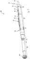
- Fig.1 shows a perspective side view of a rock drilling head 10 according to a first embodiment.
- the rock drilling head 10 has at its front end a roller bit assembly 12, also referred to as Tricone, and at its rear end 14 a first interface 16 for connecting the rock drilling head 10 to the inner linkage of a double pipe linkage and a second interface 18 for connecting the rock drilling head 10 with the outer linkage of the double pipe linkage.
- the first interface 16 and the second interface 18 each have a conical internal thread into which a conical external thread which is present at the end of the internal linkage and at the end of the external linkage can be screwed.
- the interfaces 16, 18 and the external threads of the inner linkage and the outer linkage may not have conical, ie cylindrical, threads or other connecting elements.
- the roller chisel assembly 12 comprises three roller bits 12a to 12c, which rolls upon rotation of the connected to the rock drilling head 10 inner linkage about a rotation axis 20 in the forward direction P1 in front of the rock drilling head 10 soil and thereby dissolves earth particles, so-called cuttings from the ground.
- the soil may be rock, with the roller bits then releasing rock particles upon rotation about the axis of rotation 20.
- the rock drilling head 10 may be used in a directional drilling equipment, particularly in a horizontal drilling rig, also referred to as a horizontal direction drilling apparatus.
- a drive unit drives the inner linkage and the outer linkage of the double pipe linkage with different drive heads.
- the inner linkage and the outer linkage are each composed of a plurality of linkage sections, wherein conventional linkage sections have a length in the range of 3 to 4.5 m.
- the rod sections of the inner linkage are usually bolted together.
- the linkage sections of the outer linkage are screwed together, so that both the linkage sections of the inner linkage and the linkage sections of the outer linkage are rotatably connected to each other in at least one direction of rotation.
- the inner linkage drives the roller bit assembly 12 at a speed in the range of usually 30 to 300 revolutions per minute.
- the rock drilling head 10 has an outer housing 22 and an inner tube adapter 24, at the end of which the first interface 16 is provided.
- the inner tube adapter 24 is a in FIG. 1 invisible inner tube rotatably connected to the roller chisel assembly 12 so that the inner tube adapter 24 and the inner tube transmit the rotational movement of the inner linkage to the roller chisel assembly 12.
- the rock drilling head 10 may also have a gear stage with a gear ratio or reduction, such that the speed of the inner linkage and the speed of the roller bit assembly 12 may be different.
- the outer housing 22 has a cover formed as a flange 26 which covers a provided in the outer housing 22 probe chamber 42 waterproof.
- the flange plate 26 has a window 28 of a probe material permeable material so that a probe signal can pass through the window 28. This makes it possible to locate the probe signal generated by the probe using a known locating device from the earth's surface.
- the outer housing 22 has a kink of 2 ° at a kink 30, so that the angle of the central axis of the region of the outer housing 22 before the kink 30 with respect to the central axis of the region of the outer housing 22 after the kink 30 spans an angle of 178 °.
- the kink 30 may also have an angle in the range of 1 ° to 10 °, in particular 2 ° to 5 °.
- the outer housing 22 may also have a corresponding bend, through which the roller bit assembly 12 has the same relative position to the first and second interface 16, 18 of the rock drilling head 10.
- the bending point 30 or by a corresponding bending of the outer housing 22 of the rock drilling head 10 a controlled bore is possible.
- the front part of the rock drilling head 10 is 2 ° downwards, 2 ° to the right, 2 ° to the left or 2 ° up or in a corresponding intermediate position between them, relative to the rear part of the rock drilling head 10 Layers inclined so that the drill head 10 without rotation of the outer housing 22 produces a bore with a corresponding curved course.
- the outer casing 22 of the rock drilling head 10 In order to produce a straight bore, the outer casing 22 of the rock drilling head 10 must be continuously rotated with a revolution in the range of 30 to 60 U / min.
- the outer housing 22 is connected at the rear end 14 via the second interface 18 with the outer linkage of the double pipe linkage.
- the second interface 18 preferably has an internal thread into which an external thread of the outer linkage is screwed.
- the outer rod can rotate the outer housing 22 of the rock drilling head 10 at least in one direction of rotation. If the bore produced with the help of the rock drilling head 10 have a curved course, the rotation of the outer housing 22 is stopped depending on the desired direction of bending in a required angular position and only the inner linkage for propulsion of the rock drilling head 10 driven. In addition, the rock drilling head 10 is over the linkage with the help of a drive unit pushed further into the soil.
- the rock drilling head 10 produces a curvature, ie if the rock drilling head 10 makes a turn, it supports itself with a front support plate 32 and its rear support plate 34 on the drilling channel.
- the carbide pins 38 arranged on a rear conical section 36 of the outer housing 22 serve to be able to pull the rock-boring head 10 backwards, if necessary, out of a drilling channel in a rotating manner.
- the rock drilling head 10 has, in addition to the closable by the flange 26 probe chamber 42 a waterproof by means of a flange plate 40 slip ring chamber 52 in which a sliding contact arrangement can be arranged if necessary, as will be explained in detail later.
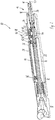
- Fig.2 shows a sectional view of the rock drilling head 10 after Fig.1 ,
- the probe chamber 42 covered with the aid of the flange plate 26 is clearly visible.
- a sensor unit 44 is arranged in the probe chamber 42.
- a first damping element 46 is located between the front end of the sensor unit 44 and the outer housing 22 viewed in the advancing direction P1
- a second damping element 48 is provided in the probe chamber 42 between the rear end of the sensor unit 44 and the outer housing 22 viewed in the advancing direction P1.
- the damping elements 46, 48 protect the electronic sensor unit 44 from shocks and impacts, which occur in particular by the drilling process.
- the sensor unit 44 is inserted with the flange plate 26 open from the side into the probe chamber 42.
- the slot 28 provided in the flange plate 26 allows a position signal emitted by the sensor unit 44 to escape to the outside, preferably as far as the earth's surface above the rock drilling head 10.
- the required energy and required data and / or signals can be transmitted via a cable 50 from the earth's surface through the double pipe linkage to the rock drilling head 10.
- the cable 50 is in Internal linkage of the double pipe linkage led to the drill head 10.
- the probe chamber 42 is located in the outer housing 22 of the rock drilling head 10.
- the drill head 10 has a in the present embodiment, two rotatably connected to a réellerohradapter 24 base body 54 circumferentially formed slip rings 56, 58 and in the outer housing 22 to the slip rings 56, 58 complementary brush assembly transferred to the outer housing 22, wherein a further cable for connecting the brush assembly and the sensor unit 44 is provided.
- the slip contact assembly 60 comprised of the slip rings 56, 58 and the complementary brush assemblies may also comprise only one slip ring and one complementary brush assembly, or more than two slip rings and two complementary brush assemblies, particularly four slip rings and four complementary brush assemblies.
- two slip rings and two complementary brush assemblies can be used to transmit the power required to power the sensor unit 44, and two data and / or signal transmission lines can be provided between a ground level control unit and the sensor unit 44
- the sensor unit 44 used only to send out locatable from the earth surface position signals, the power supply of the probe via the cable 50 and the sliding contact arrangement 60 can take place.
- the sensor unit 44 may determine the position of the rock drilling head 10 and transmit the detected position as a signal or data via the sliding contact assembly 60 and the cable 50 to a control unit on the earth's surface. Additionally or alternatively, the sensor unit 44 may be the incline of the rock drilling head 10 and / or determine the angular position of the outer housing 22 of the rock drilling head 10 and transmitted via the sliding contact assembly 60 and the cable 50 to the control unit to the earth's surface.
- the drill head can be located conventionally with a locating device from the earth's surface, then a battery-operated locatable probe can be introduced into the probe chamber 42.
- the main body with the slip rings 56, 58 can be removed from the slip ring chamber 52 when the flange plate 40 is open.
- the brush assembly is removed from the rock drilling head 10.
- the rock drilling head 10 can be used like a conventional rock drilling head without sliding contact arrangement 60 and can be used again in the rock drilling head 10 in the case of drillings requiring energy, data and / or signal transmission to and / or from the sensor unit 44 via the cable 50.
- the cable 50 can be completely removed from the inner tube adapter 24, so that the cable 50 is neither damaged nor the installation of the inner tube assembly is hindered with the réellerohradapter 24.
- the cable gland of the cable 50 into the slip ring chamber 52 is sealed by a suitable cable gland.
- the cable bushing is sealed by a corresponding blind screw or a corresponding plug, so that the slip ring chamber 52 is then sealed without cable 50 and in particular no drilling fluid can penetrate into the slip ring chamber 52.
- Sensor units 44 which are connected via a cable 50 to a control unit on the earth's surface, are also referred to as cable probes.
- a cable probe thus allows extreme holes with large detection depths and surfaces that do not allow a tracking device on the earth's surface vertically above the drill head 10. For example, when drilling under rivers or lakes, the tracking of tracking devices on the earth's surface is not readily possible. Drilling is also possible at depths where it is not possible to transfer battery-powered probes to location detectors on the surface of the earth. Both by a higher transmission power as a result of a power supply via the cable 50 and by actively determining the position of the rock drilling head 10 by means of the sensor unit 44 and transmitting position information via the cable 50 to the earth's surface holes at great depths are possible.
- the invention is based on the recognition that it is better to run the cable 50 inside the inner rod, instead of between the inner rod and the outer rod, since it can be easily damaged there due to the different speeds and / or directions of rotation. Instead, the cable 50 is guided inside the inner boom as far as the drill bit 10, the energy, data and / or signals from the cable 50 being transmitted via a sliding contact assembly 60 to the outer housing 22 of the rock drill head 10 in which the sensor unit 44 is located.
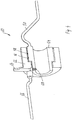
- FIG 3 the sliding contact arrangement 60 is shown in the disassembled state, wherein both the main body 54 and the brush assembly 62 are shown.
- Figure 4 shows a section through the sliding contact arrangement 60.
- the brush assembly 62 is connected via a tab 64 and a feasible through an opening of the tab 64 screw with the outer housing 22 of the rock drilling head 10.
- the brush assembly 62 is rotatably connected via the tab 64 with the probe chamber 52 and thus with the outer housing 22. Further, the brush assembly 62 is connected via a cable 66 to the sensor unit 44.
- the main body 54 with the slip rings 56, 58 is connected by a plurality of threaded pins 68 on the outer hexagon the inner rod adapter 24 secured.
- the sliding contact arrangement 60 serves, as already explained, for the electrical transmission of energy, data and / or signals from the outer housing 22 to the inner linkage.
- the cable 66 by means of a cable gland in an in Figure 5 sealed sealing region 70 sealed waterproof.
- the installation and removal of the sliding contact assembly 60 from the rock drilling head 10 is carried out by removing the flange plate 40 and the loosening of the threaded pins 68. Furthermore, the threaded rod adapter 24 is released and pulled back from the drill head 10. Furthermore, the provided for sealing cable glands on the cables 50, 66 are solved. Subsequently, the sliding contact assembly 60 can be removed with the cables 66, 50 from the slip ring chamber 52.
- the cable 50 is composed of a plurality of cable sections, which preferably correspond to the length of the linkage sections of the double pipe linkage.
- the cable ends of the cable sections are electrically connected in a suitable manner and both electrically isolated and sealed against the additionally funded by the inner rod drilling fluid.
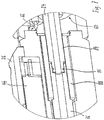
- Figure 5 is a sectional view of a section of the rock drilling head 10. The sealing of the guided through the female threaded adapter 24 cable 50 to the slip ring chamber 52 out in the areas 72 and 74th
- Figure 6 shows a section of a rear end of the rock drilling head 10 and the in Figure 7 shown detail view shows a plug connection between the inner tube adapter 24 and an inner tube 76 of the drill head 10, the rotational movement of the inner tube adapter 24 to the roller chisel assembly 12 transmits.
- the internal thread adapter 24 is mounted in the outer housing 22 via two bearings 78, 80. These are typically tapered roller bearings. Both bearings take over radial forces, bearing 80 additional thrust forces in the feed direction P1, bearing 78 additionally tensile forces against the feed direction P1. About an accessible via the slip ring chamber 52 nut 82 which is screwed onto an external thread of the inner rod adapter 24, the inner rod adapter 24 is held in this position.
- the inner rod adapter 24 In order to release the main body 54 of the sliding contact arrangement 60 from the inner tube adapter 24, after removal of the flange plate 40, an open-end wrench must be inserted into the slip ring chamber 52, by which the nut is held in position. Subsequently, the inner rod adapter 24 is rotated, so that the inner rod adapter 24 is rotated out of the nut and released from it. Subsequently, the inner rod adapter 24 can be pulled out of the drill head 10 to the rear. Near its front end, the inner rod adapter 24 has an outer hex 84 and a circumferential groove 86 into which a seal (not shown), preferably an O-ring, is inserted. The male hex 84 has a large side clearance to a hex socket 88 connected to the inner tube 76, which in turn has relatively large clearance to an outer hex of the inner tube 76. This connection allows a transmission of torque with simultaneous alignment.
- Figure 7 shows a section of the in Figure 6
- the front end of the inner rod adapter 24 has a circumferential groove 86 into which a seal, not shown, preferably an O-ring, for sealing between the inner rod adapter 24 and the inner tube 76 is introduced.
- the drilling fluid is from the inner rod passed through the inner rod adapter 24 into the interior of the inner tube 76 and therethrough to the roller bit assembly 12th
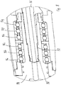
- Figure 8 shows a sectional view of a section of the drill head 10 at the transition from the inner tube 76 to the so-called Rollenmischenmelability 94.
- the inner tube 76 has at the front end an external hexagon 92 which projects with a lateral play in a complementary hexagon socket portion of the roller bit receptacle 94.
- the inner tube 76 has a circumferential groove 90 into which a seal, preferably an O-ring, is inserted for sealing between the inner tube 76 and the roller bit receptacle 94.
- a plurality of bearings 96a to 96f arranged one behind the other in the drive direction P1 are arranged, which are designed as ball bearings in the present exemplary embodiment. In other embodiments, other suitable bearings may be provided.
- the bearings 96a to 96f guide and hold the roller bit receptacle 94.
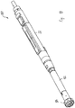
- FIG 9 and Figure 10 is a side perspective view of a drill head 100 according to a second embodiment shown.
- the drill head 100 differs from the rock drill head 10 after the Fig.1 to 8 merely in that, instead of the roller chisel arrangement 12, an in-hole hammer 102 is provided.
- This in-hole hammer 102 is driven by means of compressed air conducted through the inner linkage, through which the percussion piston of the in-hole hammer 102 is driven at up to 2,500 beats per minute.
- the percussion piston of the in-hole hammer 102 strikes directly on the drilling tool 104, the hard metal pins of which degrade the soil, in particular rock.
- the exhaust air from the in-hole hammer 102 blows the mined earth particles back through the drill channel.
- the inner rod can not be driven or alternatively rotated in the same manner as in the rock drill head 10.
- Controlled drilling with the help of Drill head 100 is carried out in the same manner as described in connection with the drill head 10, since due to the kink 30 of the drill head 100 generates a curved bore and only a rotation of the outer housing 22 allows a straight bore.
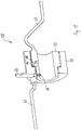
- FIG 11 is a sectional view of a sliding contact arrangement 110 according to a second embodiment shown.
- the slip rings are not provided on the circumference of the main body 112 but on an end-side section 114.
- two slip ring contacts 116, 118 are provided on the end face section 114, wherein the brush arrangement complementary to a stator 120 of the sliding contact arrangement 110 is provided for establishing an electrical contact between the slip ring contacts 116, 118 and the stator 120.
- Sliding contact assembly 110 may alternatively be used in sliding contact assembly 60 in the drill heads 10, 100.
- the sliding contact assemblies 60, 110 preferably have a base body 54, 112 with at least one slip ring 56, 68, 116, 118.
- the base body 54, 112 with the slip ring 56, 68, 116, 118 together with at least one complementary brush arrangement 62 a structural unit, which preferably can be removed together from the drill head and inserted into this.
- the sliding contact arrangement 60, 110 which can be arranged in the drill head 10, 100
- the sliding contact arrangement can also be designed as an adapter, which is arranged between a conventional drill head and the double rod.
Landscapes
- Engineering & Computer Science (AREA)
- Life Sciences & Earth Sciences (AREA)
- Geology (AREA)
- Mining & Mineral Resources (AREA)
- Physics & Mathematics (AREA)
- Environmental & Geological Engineering (AREA)
- Fluid Mechanics (AREA)
- General Life Sciences & Earth Sciences (AREA)
- Geochemistry & Mineralogy (AREA)
- Mechanical Engineering (AREA)
- Geophysics (AREA)
- Earth Drilling (AREA)
Priority Applications (1)
| Application Number | Priority Date | Filing Date | Title |
|---|---|---|---|
| PL15160434T PL2957710T3 (pl) | 2014-04-01 | 2015-03-24 | Głowica wiertnicza i urządzenie do wytwarzania otworu wiertniczego w gruncie |
Applications Claiming Priority (1)
| Application Number | Priority Date | Filing Date | Title |
|---|---|---|---|
| DE102014104552.1A DE102014104552A1 (de) | 2014-04-01 | 2014-04-01 | Bohrkopf und Vorrichtung zum Herstellen einer Bohrung im Erdreich |
Publications (2)
| Publication Number | Publication Date |
|---|---|
| EP2957710A1 EP2957710A1 (de) | 2015-12-23 |
| EP2957710B1 true EP2957710B1 (de) | 2017-12-06 |
Family
ID=53039671
Family Applications (1)
| Application Number | Title | Priority Date | Filing Date |
|---|---|---|---|
| EP15160434.5A Active EP2957710B1 (de) | 2014-04-01 | 2015-03-24 | Bohrkopf und Vorrichtung zum Herstellen einer Bohrung im Erdreich |
Country Status (4)
| Country | Link |
|---|---|
| US (1) | US9840894B2 (pl) |
| EP (1) | EP2957710B1 (pl) |
| DE (1) | DE102014104552A1 (pl) |
| PL (1) | PL2957710T3 (pl) |
Cited By (1)
| Publication number | Priority date | Publication date | Assignee | Title |
|---|---|---|---|---|
| DE102020103596A1 (de) | 2020-02-12 | 2021-08-12 | TERRA AG für Tiefbautechnik | Vorrichtung zum Erzeugen einer Erdbohrung |
Families Citing this family (10)
| Publication number | Priority date | Publication date | Assignee | Title |
|---|---|---|---|---|
| DE102013103711B4 (de) | 2013-04-12 | 2024-12-05 | AT-Boretec Inh. Andreas Tigges e. K. | Vorrichtung und Verfahren zum Bohren, insbesondere zum Horizontalbohren, mit einem Positionssensor |
| DE102015001969A1 (de) * | 2015-02-19 | 2016-08-25 | TRACTO-TECHNlK GmbH & Co. KG | Doppelrohrgestängeabschnitt, Doppelrohrgestängeschuss und Verfahren zum Ausbilden einer elektrisch leitfähigen Verbindung in einem Doppelrohrgestängeabschnitt |
| US20180120474A1 (en) * | 2017-12-18 | 2018-05-03 | Philip Teague | Methods and means for azimuthal neutron porosity imaging of formation and cement volumes surrounding a borehole |
| CN105863499B (zh) * | 2016-05-15 | 2018-02-23 | 神木市三江能源有限公司 | 一种矿井专用同步钻孔设备 |
| CN109403869B (zh) * | 2018-07-27 | 2024-02-06 | 重庆科技学院 | 一种水平定向钻扩孔用钻具 |
| US11401750B2 (en) * | 2019-09-20 | 2022-08-02 | The Charles Machine Works, Inc. | Telemetry pipe system |
| AT523416B1 (de) * | 2020-04-25 | 2021-08-15 | Think And Vision Gmbh | Vorrichtung zur Daten- und/oder Stromübertragung an einem Bohrturm oder einer Behandlungswinde |
| US11359467B2 (en) | 2020-11-03 | 2022-06-14 | Halliburton Energy Services, Inc. | Rotating electrical connection for perforating systems |
| CN114562197B (zh) * | 2022-03-02 | 2024-11-12 | 桂林中旺机械制造有限公司 | 具有返打功能的液压凿岩机 |
| CN115822503B (zh) * | 2022-11-07 | 2026-02-27 | 北京中煤矿山工程有限公司 | 一种曲率钻孔孔口密封装置 |
Family Cites Families (5)
| Publication number | Priority date | Publication date | Assignee | Title |
|---|---|---|---|---|
| US4544215A (en) * | 1983-08-09 | 1985-10-01 | Fritsch Joseph E | Self-contained slip ring assembly |
| DE10005475A1 (de) * | 2000-02-08 | 2001-08-09 | Guenter Klemm | Bohrvorrichtung |
| US7320363B2 (en) * | 2003-04-02 | 2008-01-22 | Halliburton Energy Services, Inc. | Energized slip ring assembly |
| US8157002B2 (en) * | 2009-07-21 | 2012-04-17 | Smith International Inc. | Slip ring apparatus for a rotary steerable tool |
| US9284793B2 (en) * | 2013-11-13 | 2016-03-15 | Halliburton Energy Services, Inc. | Externally serviceable slip ring apparatus |
-
2014
- 2014-04-01 DE DE102014104552.1A patent/DE102014104552A1/de not_active Ceased
-
2015
- 2015-03-18 US US14/661,630 patent/US9840894B2/en not_active Expired - Fee Related
- 2015-03-24 EP EP15160434.5A patent/EP2957710B1/de active Active
- 2015-03-24 PL PL15160434T patent/PL2957710T3/pl unknown
Non-Patent Citations (1)
| Title |
|---|
| None * |
Cited By (2)
| Publication number | Priority date | Publication date | Assignee | Title |
|---|---|---|---|---|
| DE102020103596A1 (de) | 2020-02-12 | 2021-08-12 | TERRA AG für Tiefbautechnik | Vorrichtung zum Erzeugen einer Erdbohrung |
| EP3865655A1 (de) | 2020-02-12 | 2021-08-18 | TERRA AG fuer Tiefbautechnik | Vorrichtung zum erzeugen einer erdbohrung |
Also Published As
| Publication number | Publication date |
|---|---|
| PL2957710T3 (pl) | 2018-04-30 |
| DE102014104552A1 (de) | 2015-10-01 |
| EP2957710A1 (de) | 2015-12-23 |
| US9840894B2 (en) | 2017-12-12 |
| US20150275626A1 (en) | 2015-10-01 |
Similar Documents
| Publication | Publication Date | Title |
|---|---|---|
| EP2957710A1 (de) | Bohrkopf und Vorrichtung zum Herstellen einer Bohrung im Erdreich | |
| EP2085566B1 (de) | Bohranlage | |
| DE60117372T2 (de) | Vorrichtung und verfahren zur herstellung einer lateralbohrung | |
| EP2553201B1 (de) | Verfahren zum erstellen einer horizontalbohrung im erdreich und horizontalbohrvorrichtung | |
| DE102015105908A1 (de) | Bohrgerät zum Erstellen einer verrohrten Bohrung und Verfahren zum Betreiben eines Bohrgerätes | |
| DE3687855T2 (de) | Fuehrungs- und steuerungssystem fuer schlagbohrwerkzeuge. | |
| EP2553202B1 (de) | Verfahren zum betrieb einer horizontalbohrvorrichtung und horizontalbohrvorrichtung | |
| DE102011010958A1 (de) | Steckverbindung und Gestängeschuss für Bohrgestänge | |
| DE2924393A1 (de) | Bohrvorrichtung zum ueberlagerungsbohren | |
| EP2553203B1 (de) | Horizontalbohrvorrichtung | |
| DE102006054435B4 (de) | Verfahren zum Einbringen einer Erdwärmesonde in das Erdreich und eine Vorrichtung | |
| DE102011000320A1 (de) | Bohranlage zum Durchführen von Bohrungen im Erdreich | |
| EP3828375B1 (de) | Kabelhaspel zum einbringen eines datenführungskabels in einen bohrstrang, insbesondere einer horizontalbohranlage | |
| DE102014009630A1 (de) | Verfahren und Vorrichtung zur Erstellung eines Bohrlochs | |
| WO2014048627A2 (de) | Vorrichtung und verfahren zur verlegung einer rohrleitung in einem bohrloch | |
| DE2924392A1 (de) | Bohrvorrichtung zum ueberlagerungsbohren | |
| DE102011109330A1 (de) | Steuerbare Bohrvorrichtung | |
| EP3259434B1 (de) | "doppelrohrgestängeabschnitt, doppelrohrgestängeschuss und verfahren zum ausbilden einer elektrisch leitfähigen verbindung in einem doppelrohrgestängeabschnitt" | |
| DE102008034083B4 (de) | Erdbohrvorrichtung | |
| DE102020130462B4 (de) | Verwendung eines Imlochhammers und einer Imlochhammervorrichtung | |
| DE10211833A1 (de) | Vorrichtung zum grabenlosen Austauschen von Leitungen | |
| EP3663504B1 (de) | Erdbauverfahren, erdbauvorrichtung und erdbauinstallation | |
| DE3126354C2 (de) | Verfahren und Einrichtung zur Herstellung von Bohrlöchern im Erdreich | |
| DE10116103A1 (de) | Vorrichtung zum Auffahren einer unterirdischen Bohrung | |
| DE102012003120A1 (de) | Verfahren und Vorrichtungen zur Verlegung von Rohrleitungen im Boden |
Legal Events
| Date | Code | Title | Description |
|---|---|---|---|
| PUAI | Public reference made under article 153(3) epc to a published international application that has entered the european phase |
Free format text: ORIGINAL CODE: 0009012 |
|
| AK | Designated contracting states |
Kind code of ref document: A1 Designated state(s): AL AT BE BG CH CY CZ DE DK EE ES FI FR GB GR HR HU IE IS IT LI LT LU LV MC MK MT NL NO PL PT RO RS SE SI SK SM TR |
|
| AX | Request for extension of the european patent |
Extension state: BA ME |
|
| 17P | Request for examination filed |
Effective date: 20160621 |
|
| RBV | Designated contracting states (corrected) |
Designated state(s): AL AT BE BG CH CY CZ DE DK EE ES FI FR GB GR HR HU IE IS IT LI LT LU LV MC MK MT NL NO PL PT RO RS SE SI SK SM TR |
|
| GRAP | Despatch of communication of intention to grant a patent |
Free format text: ORIGINAL CODE: EPIDOSNIGR1 |
|
| STAA | Information on the status of an ep patent application or granted ep patent |
Free format text: STATUS: GRANT OF PATENT IS INTENDED |
|
| INTG | Intention to grant announced |
Effective date: 20170630 |
|
| GRAS | Grant fee paid |
Free format text: ORIGINAL CODE: EPIDOSNIGR3 |
|
| GRAA | (expected) grant |
Free format text: ORIGINAL CODE: 0009210 |
|
| STAA | Information on the status of an ep patent application or granted ep patent |
Free format text: STATUS: THE PATENT HAS BEEN GRANTED |
|
| AK | Designated contracting states |
Kind code of ref document: B1 Designated state(s): AL AT BE BG CH CY CZ DE DK EE ES FI FR GB GR HR HU IE IS IT LI LT LU LV MC MK MT NL NO PL PT RO RS SE SI SK SM TR |
|
| REG | Reference to a national code |
Ref country code: GB Ref legal event code: FG4D Free format text: NOT ENGLISH |
|
| REG | Reference to a national code |
Ref country code: AT Ref legal event code: REF Ref document number: 952556 Country of ref document: AT Kind code of ref document: T Effective date: 20171215 Ref country code: CH Ref legal event code: EP |
|
| REG | Reference to a national code |
Ref country code: IE Ref legal event code: FG4D Free format text: LANGUAGE OF EP DOCUMENT: GERMAN |
|
| REG | Reference to a national code |
Ref country code: CH Ref legal event code: NV Representative=s name: SCHNEIDER FELDMANN AG PATENT- UND MARKENANWAEL, CH |
|
| REG | Reference to a national code |
Ref country code: DE Ref legal event code: R096 Ref document number: 502015002472 Country of ref document: DE |
|
| REG | Reference to a national code |
Ref country code: FR Ref legal event code: PLFP Year of fee payment: 4 |
|
| REG | Reference to a national code |
Ref country code: NL Ref legal event code: MP Effective date: 20171206 |
|
| REG | Reference to a national code |
Ref country code: LT Ref legal event code: MG4D |
|
| PG25 | Lapsed in a contracting state [announced via postgrant information from national office to epo] |
Ref country code: SE Free format text: LAPSE BECAUSE OF FAILURE TO SUBMIT A TRANSLATION OF THE DESCRIPTION OR TO PAY THE FEE WITHIN THE PRESCRIBED TIME-LIMIT Effective date: 20171206 Ref country code: ES Free format text: LAPSE BECAUSE OF FAILURE TO SUBMIT A TRANSLATION OF THE DESCRIPTION OR TO PAY THE FEE WITHIN THE PRESCRIBED TIME-LIMIT Effective date: 20171206 Ref country code: FI Free format text: LAPSE BECAUSE OF FAILURE TO SUBMIT A TRANSLATION OF THE DESCRIPTION OR TO PAY THE FEE WITHIN THE PRESCRIBED TIME-LIMIT Effective date: 20171206 Ref country code: LT Free format text: LAPSE BECAUSE OF FAILURE TO SUBMIT A TRANSLATION OF THE DESCRIPTION OR TO PAY THE FEE WITHIN THE PRESCRIBED TIME-LIMIT Effective date: 20171206 Ref country code: NO Free format text: LAPSE BECAUSE OF FAILURE TO SUBMIT A TRANSLATION OF THE DESCRIPTION OR TO PAY THE FEE WITHIN THE PRESCRIBED TIME-LIMIT Effective date: 20180306 |
|
| PG25 | Lapsed in a contracting state [announced via postgrant information from national office to epo] |
Ref country code: BG Free format text: LAPSE BECAUSE OF FAILURE TO SUBMIT A TRANSLATION OF THE DESCRIPTION OR TO PAY THE FEE WITHIN THE PRESCRIBED TIME-LIMIT Effective date: 20180306 Ref country code: HR Free format text: LAPSE BECAUSE OF FAILURE TO SUBMIT A TRANSLATION OF THE DESCRIPTION OR TO PAY THE FEE WITHIN THE PRESCRIBED TIME-LIMIT Effective date: 20171206 Ref country code: LV Free format text: LAPSE BECAUSE OF FAILURE TO SUBMIT A TRANSLATION OF THE DESCRIPTION OR TO PAY THE FEE WITHIN THE PRESCRIBED TIME-LIMIT Effective date: 20171206 Ref country code: GR Free format text: LAPSE BECAUSE OF FAILURE TO SUBMIT A TRANSLATION OF THE DESCRIPTION OR TO PAY THE FEE WITHIN THE PRESCRIBED TIME-LIMIT Effective date: 20180307 Ref country code: RS Free format text: LAPSE BECAUSE OF FAILURE TO SUBMIT A TRANSLATION OF THE DESCRIPTION OR TO PAY THE FEE WITHIN THE PRESCRIBED TIME-LIMIT Effective date: 20171206 |
|
| PG25 | Lapsed in a contracting state [announced via postgrant information from national office to epo] |
Ref country code: NL Free format text: LAPSE BECAUSE OF FAILURE TO SUBMIT A TRANSLATION OF THE DESCRIPTION OR TO PAY THE FEE WITHIN THE PRESCRIBED TIME-LIMIT Effective date: 20171206 |
|
| PG25 | Lapsed in a contracting state [announced via postgrant information from national office to epo] |
Ref country code: CZ Free format text: LAPSE BECAUSE OF FAILURE TO SUBMIT A TRANSLATION OF THE DESCRIPTION OR TO PAY THE FEE WITHIN THE PRESCRIBED TIME-LIMIT Effective date: 20171206 Ref country code: SK Free format text: LAPSE BECAUSE OF FAILURE TO SUBMIT A TRANSLATION OF THE DESCRIPTION OR TO PAY THE FEE WITHIN THE PRESCRIBED TIME-LIMIT Effective date: 20171206 Ref country code: EE Free format text: LAPSE BECAUSE OF FAILURE TO SUBMIT A TRANSLATION OF THE DESCRIPTION OR TO PAY THE FEE WITHIN THE PRESCRIBED TIME-LIMIT Effective date: 20171206 |
|
| PG25 | Lapsed in a contracting state [announced via postgrant information from national office to epo] |
Ref country code: IT Free format text: LAPSE BECAUSE OF FAILURE TO SUBMIT A TRANSLATION OF THE DESCRIPTION OR TO PAY THE FEE WITHIN THE PRESCRIBED TIME-LIMIT Effective date: 20171206 Ref country code: RO Free format text: LAPSE BECAUSE OF FAILURE TO SUBMIT A TRANSLATION OF THE DESCRIPTION OR TO PAY THE FEE WITHIN THE PRESCRIBED TIME-LIMIT Effective date: 20171206 Ref country code: SM Free format text: LAPSE BECAUSE OF FAILURE TO SUBMIT A TRANSLATION OF THE DESCRIPTION OR TO PAY THE FEE WITHIN THE PRESCRIBED TIME-LIMIT Effective date: 20171206 |
|
| REG | Reference to a national code |
Ref country code: DE Ref legal event code: R097 Ref document number: 502015002472 Country of ref document: DE |
|
| PG25 | Lapsed in a contracting state [announced via postgrant information from national office to epo] |
Ref country code: MT Free format text: LAPSE BECAUSE OF FAILURE TO SUBMIT A TRANSLATION OF THE DESCRIPTION OR TO PAY THE FEE WITHIN THE PRESCRIBED TIME-LIMIT Effective date: 20171206 |
|
| PLBE | No opposition filed within time limit |
Free format text: ORIGINAL CODE: 0009261 |
|
| STAA | Information on the status of an ep patent application or granted ep patent |
Free format text: STATUS: NO OPPOSITION FILED WITHIN TIME LIMIT |
|
| 26N | No opposition filed |
Effective date: 20180907 |
|
| PG25 | Lapsed in a contracting state [announced via postgrant information from national office to epo] |
Ref country code: MC Free format text: LAPSE BECAUSE OF FAILURE TO SUBMIT A TRANSLATION OF THE DESCRIPTION OR TO PAY THE FEE WITHIN THE PRESCRIBED TIME-LIMIT Effective date: 20171206 Ref country code: SI Free format text: LAPSE BECAUSE OF FAILURE TO SUBMIT A TRANSLATION OF THE DESCRIPTION OR TO PAY THE FEE WITHIN THE PRESCRIBED TIME-LIMIT Effective date: 20171206 Ref country code: DK Free format text: LAPSE BECAUSE OF FAILURE TO SUBMIT A TRANSLATION OF THE DESCRIPTION OR TO PAY THE FEE WITHIN THE PRESCRIBED TIME-LIMIT Effective date: 20171206 |
|
| REG | Reference to a national code |
Ref country code: BE Ref legal event code: MM Effective date: 20180331 |
|
| REG | Reference to a national code |
Ref country code: IE Ref legal event code: MM4A |
|
| PG25 | Lapsed in a contracting state [announced via postgrant information from national office to epo] |
Ref country code: LU Free format text: LAPSE BECAUSE OF NON-PAYMENT OF DUE FEES Effective date: 20180324 |
|
| PG25 | Lapsed in a contracting state [announced via postgrant information from national office to epo] |
Ref country code: IE Free format text: LAPSE BECAUSE OF NON-PAYMENT OF DUE FEES Effective date: 20180324 |
|
| PG25 | Lapsed in a contracting state [announced via postgrant information from national office to epo] |
Ref country code: BE Free format text: LAPSE BECAUSE OF NON-PAYMENT OF DUE FEES Effective date: 20180331 |
|
| GBPC | Gb: european patent ceased through non-payment of renewal fee |
Effective date: 20190324 |
|
| PG25 | Lapsed in a contracting state [announced via postgrant information from national office to epo] |
Ref country code: GB Free format text: LAPSE BECAUSE OF NON-PAYMENT OF DUE FEES Effective date: 20190324 |
|
| PG25 | Lapsed in a contracting state [announced via postgrant information from national office to epo] |
Ref country code: TR Free format text: LAPSE BECAUSE OF FAILURE TO SUBMIT A TRANSLATION OF THE DESCRIPTION OR TO PAY THE FEE WITHIN THE PRESCRIBED TIME-LIMIT Effective date: 20171206 |
|
| PG25 | Lapsed in a contracting state [announced via postgrant information from national office to epo] |
Ref country code: PT Free format text: LAPSE BECAUSE OF FAILURE TO SUBMIT A TRANSLATION OF THE DESCRIPTION OR TO PAY THE FEE WITHIN THE PRESCRIBED TIME-LIMIT Effective date: 20171206 |
|
| PG25 | Lapsed in a contracting state [announced via postgrant information from national office to epo] |
Ref country code: HU Free format text: LAPSE BECAUSE OF FAILURE TO SUBMIT A TRANSLATION OF THE DESCRIPTION OR TO PAY THE FEE WITHIN THE PRESCRIBED TIME-LIMIT; INVALID AB INITIO Effective date: 20150324 Ref country code: CY Free format text: LAPSE BECAUSE OF FAILURE TO SUBMIT A TRANSLATION OF THE DESCRIPTION OR TO PAY THE FEE WITHIN THE PRESCRIBED TIME-LIMIT Effective date: 20171206 Ref country code: MK Free format text: LAPSE BECAUSE OF NON-PAYMENT OF DUE FEES Effective date: 20171206 |
|
| PG25 | Lapsed in a contracting state [announced via postgrant information from national office to epo] |
Ref country code: AL Free format text: LAPSE BECAUSE OF FAILURE TO SUBMIT A TRANSLATION OF THE DESCRIPTION OR TO PAY THE FEE WITHIN THE PRESCRIBED TIME-LIMIT Effective date: 20171206 Ref country code: IS Free format text: LAPSE BECAUSE OF FAILURE TO SUBMIT A TRANSLATION OF THE DESCRIPTION OR TO PAY THE FEE WITHIN THE PRESCRIBED TIME-LIMIT Effective date: 20180406 |
|
| REG | Reference to a national code |
Ref country code: CH Ref legal event code: PFA Owner name: TERRA AG FUER TIEFBAUTECHNIK, CH Free format text: FORMER OWNER: TERRA AG FUER TIEFBAUTECHNIK, CH |
|
| REG | Reference to a national code |
Ref country code: AT Ref legal event code: MM01 Ref document number: 952556 Country of ref document: AT Kind code of ref document: T Effective date: 20200324 |
|
| PG25 | Lapsed in a contracting state [announced via postgrant information from national office to epo] |
Ref country code: AT Free format text: LAPSE BECAUSE OF NON-PAYMENT OF DUE FEES Effective date: 20200324 |
|
| PGFP | Annual fee paid to national office [announced via postgrant information from national office to epo] |
Ref country code: DE Payment date: 20250326 Year of fee payment: 11 |
|
| PGFP | Annual fee paid to national office [announced via postgrant information from national office to epo] |
Ref country code: CH Payment date: 20250401 Year of fee payment: 11 |
|
| REG | Reference to a national code |
Ref country code: CH Ref legal event code: U11 Free format text: ST27 STATUS EVENT CODE: U-0-0-U10-U11 (AS PROVIDED BY THE NATIONAL OFFICE) Effective date: 20260401 |
|
| PGFP | Annual fee paid to national office [announced via postgrant information from national office to epo] |
Ref country code: FR Payment date: 20260324 Year of fee payment: 12 |
|
| PGFP | Annual fee paid to national office [announced via postgrant information from national office to epo] |
Ref country code: PL Payment date: 20260216 Year of fee payment: 12 |