EP2957718A1 - Turbine - Google Patents
Turbine Download PDFInfo
- Publication number
- EP2957718A1 EP2957718A1 EP14172926.9A EP14172926A EP2957718A1 EP 2957718 A1 EP2957718 A1 EP 2957718A1 EP 14172926 A EP14172926 A EP 14172926A EP 2957718 A1 EP2957718 A1 EP 2957718A1
- Authority
- EP
- European Patent Office
- Prior art keywords
- turbine
- housing
- shroud
- labyrinth seal
- sealing
- Prior art date
- Legal status (The legal status is an assumption and is not a legal conclusion. Google has not performed a legal analysis and makes no representation as to the accuracy of the status listed.)
- Withdrawn
Links
- 238000007789 sealing Methods 0.000 claims abstract description 45
- 238000000576 coating method Methods 0.000 claims abstract description 23
- 239000011248 coating agent Substances 0.000 claims abstract description 19
- 208000004350 Strabismus Diseases 0.000 claims description 4
- 235000009854 Cucurbita moschata Nutrition 0.000 claims description 3
- 240000001980 Cucurbita pepo Species 0.000 claims description 3
- 235000009852 Cucurbita pepo Nutrition 0.000 claims description 3
- 239000000919 ceramic Substances 0.000 claims description 3
- RVTZCBVAJQQJTK-UHFFFAOYSA-N oxygen(2-);zirconium(4+) Chemical compound [O-2].[O-2].[Zr+4] RVTZCBVAJQQJTK-UHFFFAOYSA-N 0.000 claims description 3
- 235000020354 squash Nutrition 0.000 claims description 3
- 229910001928 zirconium oxide Inorganic materials 0.000 claims description 3
- 239000007789 gas Substances 0.000 description 21
- PXHVJJICTQNCMI-UHFFFAOYSA-N Nickel Chemical compound [Ni] PXHVJJICTQNCMI-UHFFFAOYSA-N 0.000 description 6
- 238000002485 combustion reaction Methods 0.000 description 6
- MCMNRKCIXSYSNV-UHFFFAOYSA-N Zirconium dioxide Chemical compound O=[Zr]=O MCMNRKCIXSYSNV-UHFFFAOYSA-N 0.000 description 4
- 230000000694 effects Effects 0.000 description 4
- 239000000203 mixture Substances 0.000 description 4
- 230000006378 damage Effects 0.000 description 3
- 229910052759 nickel Inorganic materials 0.000 description 3
- 239000012720 thermal barrier coating Substances 0.000 description 3
- XAGFODPZIPBFFR-UHFFFAOYSA-N aluminium Chemical compound [Al] XAGFODPZIPBFFR-UHFFFAOYSA-N 0.000 description 2
- 230000001680 brushing effect Effects 0.000 description 2
- 239000011651 chromium Substances 0.000 description 2
- 239000012530 fluid Substances 0.000 description 2
- 239000000446 fuel Substances 0.000 description 2
- 238000000034 method Methods 0.000 description 2
- VYZAMTAEIAYCRO-UHFFFAOYSA-N Chromium Chemical compound [Cr] VYZAMTAEIAYCRO-UHFFFAOYSA-N 0.000 description 1
- 229910001182 Mo alloy Inorganic materials 0.000 description 1
- 229910001069 Ti alloy Inorganic materials 0.000 description 1
- 238000005299 abrasion Methods 0.000 description 1
- 229910052782 aluminium Inorganic materials 0.000 description 1
- 230000015572 biosynthetic process Effects 0.000 description 1
- 239000011449 brick Substances 0.000 description 1
- 238000005266 casting Methods 0.000 description 1
- 229910010293 ceramic material Inorganic materials 0.000 description 1
- 229910052804 chromium Inorganic materials 0.000 description 1
- 239000010941 cobalt Substances 0.000 description 1
- 229910017052 cobalt Inorganic materials 0.000 description 1
- GUTLYIVDDKVIGB-UHFFFAOYSA-N cobalt atom Chemical compound [Co] GUTLYIVDDKVIGB-UHFFFAOYSA-N 0.000 description 1
- 239000000567 combustion gas Substances 0.000 description 1
- 238000001816 cooling Methods 0.000 description 1
- 230000007797 corrosion Effects 0.000 description 1
- 238000005260 corrosion Methods 0.000 description 1
- 230000006735 deficit Effects 0.000 description 1
- 230000006866 deterioration Effects 0.000 description 1
- 238000006073 displacement reaction Methods 0.000 description 1
- 230000003628 erosive effect Effects 0.000 description 1
- 230000002349 favourable effect Effects 0.000 description 1
- 229910052742 iron Inorganic materials 0.000 description 1
- 239000007788 liquid Substances 0.000 description 1
- 238000004519 manufacturing process Methods 0.000 description 1
- MGRWKWACZDFZJT-UHFFFAOYSA-N molybdenum tungsten Chemical compound [Mo].[W] MGRWKWACZDFZJT-UHFFFAOYSA-N 0.000 description 1
- 230000001681 protective effect Effects 0.000 description 1
- 238000004064 recycling Methods 0.000 description 1
- 239000012858 resilient material Substances 0.000 description 1
- 239000000126 substance Substances 0.000 description 1
- 229910000601 superalloy Inorganic materials 0.000 description 1
- 230000008646 thermal stress Effects 0.000 description 1
- 238000011144 upstream manufacturing Methods 0.000 description 1
- 229910052727 yttrium Inorganic materials 0.000 description 1
- VWQVUPCCIRVNHF-UHFFFAOYSA-N yttrium atom Chemical compound [Y] VWQVUPCCIRVNHF-UHFFFAOYSA-N 0.000 description 1
Images

Classifications
-
- F—MECHANICAL ENGINEERING; LIGHTING; HEATING; WEAPONS; BLASTING
- F01—MACHINES OR ENGINES IN GENERAL; ENGINE PLANTS IN GENERAL; STEAM ENGINES
- F01D—NON-POSITIVE DISPLACEMENT MACHINES OR ENGINES, e.g. STEAM TURBINES
- F01D11/00—Preventing or minimising internal leakage of working-fluid, e.g. between stages
- F01D11/08—Preventing or minimising internal leakage of working-fluid, e.g. between stages for sealing space between rotor blade tips and stator
- F01D11/12—Preventing or minimising internal leakage of working-fluid, e.g. between stages for sealing space between rotor blade tips and stator using a rubstrip, e.g. erodible. deformable or resiliently-biased part
- F01D11/122—Preventing or minimising internal leakage of working-fluid, e.g. between stages for sealing space between rotor blade tips and stator using a rubstrip, e.g. erodible. deformable or resiliently-biased part with erodable or abradable material
-
- F—MECHANICAL ENGINEERING; LIGHTING; HEATING; WEAPONS; BLASTING
- F01—MACHINES OR ENGINES IN GENERAL; ENGINE PLANTS IN GENERAL; STEAM ENGINES
- F01D—NON-POSITIVE DISPLACEMENT MACHINES OR ENGINES, e.g. STEAM TURBINES
- F01D5/00—Blades; Blade-carrying members; Heating, heat-insulating, cooling or antivibration means on the blades or the members
- F01D5/12—Blades
- F01D5/22—Blade-to-blade connections, e.g. for damping vibrations
- F01D5/225—Blade-to-blade connections, e.g. for damping vibrations by shrouding
Definitions
- the invention relates to a turbine, comprising a blade row whose blades are connected to a shroud, and a housing enclosing the blade row, wherein between the shroud and the housing, a labyrinth seal is formed, the at least one arranged on the housing and on the shroud, at least over one Part of the circumference extending sealing rib comprises.
- a turbine is a turbomachine in which a pressurized gas expands.
- a hot and compressed gas is released, converting thermal energy into mechanical energy.
- superheated steam generated here in a steam generator is used here, in the gas turbine, a hot gas (mixture of combustion gas and air).
- the hot gas is produced by burning a gaseous or liquid fuel in a combustion chamber, which is further supplied compressed air from an upstream.
- the energy obtained is used for example in power plants to drive a generator, wherein a part of the energy is provided in the gas turbine for driving the compressor.
- the rotating rotor in the turbine with its blades moves relative to the housing enclosing the turbine, wherein between the rotor and the housing, a gap is provided, which is required for free mobility of the rotor. Through this gap always occurs a certain leakage flow, which reduces the efficiency of the turbine.
- the labyrinth seals are often designed for a controlled brushing of the blade tips.
- the potential Anstreif vom are honeycomb-like structure.
- such a design of the rubbing surfaces means a particularly high technical complexity.
- the invention is therefore based on the object to provide a turbine of the type mentioned, which achieves a particularly high efficiency with technically simple means.
- This object is achieved according to the invention by having a surface of the labyrinth seal, which has a radial normal, a squint coating.
- the invention is based on the consideration that the hitherto used honeycomb structures in the field of brushing are particularly complex and therefore expensive to produce and should therefore be replaced by simpler, more favorable structures.
- the alternative structures should have similar properties, ie be suitable for the ambient conditions in the flow channel of a turbine and have the same abrasion properties, ie rub as lightly as possible on rubbing and thereby generate no residues damaging to the subsequent turbine stages. This is possible by means of a corresponding Anstreifbe harshung. This can be applied to the corresponding surfaces in a technically simple manner and has the desired properties.
- the rubbing coating comprises an MCrAlY rubbing layer.
- M may be cobalt (Co) or nickel (Ni) or a corresponding mixture.
- Such coatings are particularly heat-resistant and are therefore also suitable for gas turbines.
- Chromium (Cr) and aluminum (A1) form protective oxide layers, while yttrium (Y) promotes the formation of such layers.
- Abst harshen can be applied in a simple manner by a variety of known processes.
- the squigg coating comprises a ceramic stripping layer, in particular a zirconium oxide-based rubbing layer. Ceramics are also particularly heat resistant and have the porosity needed for a squish layer. In particular, zirconium (IV) oxide is very stable and has high resistance to chemical, thermal and mechanical influences.
- the surface of the labyrinth seal, to which the squint coating is applied is arranged on the housing. This makes it possible, in particular, to retrofit the existing housing areas by replacing the corresponding housing walls or subsequent coating of the housing walls.
- the sealing rib disposed on the shroud has radially on the surface, which is provided with the coating, d. H. the sealing rib touches the surface when radially expanded.
- the sealing ribs on the housing and on the shroud are advantageously formed overlapping in the axial direction, ie when looking in the axial direction, the labyrinth seal is opaque. This is achieved by a correspondingly large extent of the sealing ribs in the direction of the respective opposite Component (shroud or housing) reached. The sealing ribs thus interlock (meshing).
- the squint coating extends in the axial direction advantageously completely between the sealing ribs arranged on the housing. As a result, it is ensured even with a temperature-induced or actively induced axial displacement of the rotor that the sealing ribs of the shroud always strip on expansion on a coated surface.
- the labyrinth seal advantageously has a circumferentially uniform longitudinal section. Due to the rotational or radial symmetry of the rotor, a correspondingly good seal is thus achieved along the entire circumference.
- the sealing rib arranged on the housing is formed integrally with the housing. Accordingly, advantageously arranged on the shroud seal rib is formed integrally with the shroud. As a result, the production of the corresponding sealing ribs is simplified because they can be formed, for example, by casting or drawing directly with the corresponding components.
- the turbine is advantageously designed as a gas turbine. Especially in gas turbines, the temperatures are particularly high, so that a thermal expansion of the turbine blades and other components is expected.
- the use of an abradable coating in labyrinth seals is of particular advantage.
- a power plant advantageously comprises such a turbine.
- the advantages achieved by the invention are in particular that the use of honeycomb surfaces is unnecessary by the application of an abradable coating between the sealing ribs of a labyrinth seal on a blade row with shroud and thus the sealing effort is significantly reduced while maintaining efficiency.
- the costs are thereby reduced and the effort is also significantly reduced in the recycling of labyrinth seals.
- the coatings also lead due to their easy abrasiveness to less damage to the sealing ribs of the shroud, so that the gap dimensions can be further reduced, which further increases the efficiency.
- the coating does not have to be cooled, which further increases the technical complexity and the efficiency.
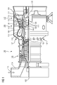
- the in the FIG. 1 shown turbine is a gas turbine 100 and has inside a about an axis of rotation 102 (axial direction) rotatably mounted rotor 103, which is also referred to as a turbine runner. If the terms axial, radial, circumferential direction or comparable terms are used in the following or in the preceding text of the description, they always refer to the axis of rotation 102 of the gas turbine 100.
- the rotor 103 successively follow an intake housing 104, a compressor 105, a toroidal combustion chamber 106, here an annular combustion chamber, with a plurality of coaxially arranged burners 107, a turbine 108 and the exhaust housing 109.
- the burner 107 each comprise a pilot burner not shown in detail, which serves to increase the flame stability, especially in the partial load range.
- the vanes 130 are attached to the stator 143, whereas the blades 120 of a row 125 are mounted on the rotor 103 by means of a turbine disk 133.
- the rotor blades 120 thus form components of the rotor or rotor 103.
- Coupled to the rotor 103 is a generator or a working machine (not shown).
- air 105 is sucked in and compressed by the compressor 105 through the intake housing 104.
- the compressed air provided at the turbine-side end of the compressor 105 is supplied to the burners 107 where it is mixed with a fuel.
- the mixture is then formed to form the working medium 113 in the combustion chamber 106 burned. From there, the working fluid 113 flows along the main flow passage 111 past the vanes 130 and the blades 120.
- the components exposed to the hot working medium 113 are subject to thermal loads during operation of the gas turbine 100.
- temperatures prevail of up to 1500 degrees Celsius, as higher temperatures mean better efficiency.
- the guide vanes 130 and rotor blades 120 in particular the first turbine stage 112 seen in the direction of flow of the working medium 113, are subjected to the greatest thermal stress in addition to the heat shield bricks lining the annular combustion chamber 106.
- the high loads make highly resilient materials necessary.
- the turbine blades 120, 130 are therefore made of titanium alloys, nickel superalloy, or tungsten-molybdenum alloys.
- the heat-shield coating is called Thermal Barrier Coating or TBC for short.
- Other measures to make the blades more resistant to heat consist of sophisticated cooling duct systems. This technique is used in both the guide and rotor blades 120, 130.
- Each vane 130 has, in addition to the actual airfoil, a vane foot, also referred to as a platform 144, facing the inner casing 138 of the turbine 108 and a vane head opposite the vane root.
- the Leitschaufelkopf faces the rotor 103 and fixed to an inner ring 140 of the stator 143.
- Each inner ring 140 encloses the shaft of the rotor 103.
- each blade has such a blade root, but ends in a blade tip.
- FIG. 2 3 shows a rotor blade 120 in the turbine 108 in a longitudinal section in the upper part of the gas turbine 100.
- the gap 146 is formed between the blade 120 and the housing 138. In the FIG. 2 shown embodiment is conceivable in each blade row 125.
- the leakage flow reduces the gas mass which flows through the rotor 103, so that the extracted work is less.
- the flow caused by the gap 146 results in an impairment of the actual flow through the turbine 108, since it has different angles and different local velocities. This results in a mixture of the two streams and in a reduction of the aerodynamic efficiency.
- the leakage flow also leads to a deterioration of the flow of a subsequent vane row 115.
- the gap 146 is therefore provided with a labyrinth seal 148.
- the blades 120 of the blade row 125 are connected to a shroud 150, which is annular along the entire circumference around the Blade 125 extends and connects the blade tips.
- the shroud 150 also stabilizes the blade row 125 against vibration.
- the labyrinth seal 148 and its components are described below with reference to their longitudinal section, which is consistent along the entire circumference.
- On the shroud are two radially outwardly extending sealing ribs 152 are arranged, which taper slightly to the outside, but otherwise have a substantially rectangular longitudinal section.
- On the housing 138 three equally spaced equally formed sealing ribs 154 are arranged, which extend radially inwardly correspondingly. However, they are radially shorter than the sealing ribs 152 on the shroud 150th
- the sealing ribs 152 arranged on the shroud 150 are designed in one piece with the shroud 150.
- the sealing ribs 154 arranged on the housing 138 are made in one piece with the component of the housing 138 arranged correspondingly there.
- seal ribs 154 on housing 138 corresponds to the spacing of seal ribs 152 on shroud 152.
- all seal ribs 152, 154 are equally spaced such that seal ribs 154 on housing 138 and seal ribs 152 on shroud 150 alternate. They are designed overlapping and thus interlock. This is achieved by placing the tips of the sealing ribs 152 of the shroud 150 as close as possible to the housing 138.
- the sealing ribs 152 of the shroud 150 should be made to extend as close as possible to the housing 138.
- the labyrinth seal 148 which extends between the sealing ribs 154 of the housing 138 and the sealing ribs 152 of the shroud 150 is disposed opposite, a along the entire circumference stretched coating 156 applied.
- the squash coating 156 may include ceramic materials such as. As zirconium oxide or metallic coatings such. B. MCrAlY include. When touched by the sealing ribs 152 of the shroud 150, the abradable coating 156 is removed and there is no damage, nor is the gas turbine 100 braked by friction. As a result, the gap 146 can be minimized and the efficiency of the gas turbine 100 is optimized.
Landscapes
- Engineering & Computer Science (AREA)
- Mechanical Engineering (AREA)
- General Engineering & Computer Science (AREA)
- Turbine Rotor Nozzle Sealing (AREA)
Priority Applications (1)
| Application Number | Priority Date | Filing Date | Title |
|---|---|---|---|
| EP14172926.9A EP2957718A1 (fr) | 2014-06-18 | 2014-06-18 | Turbine |
Applications Claiming Priority (1)
| Application Number | Priority Date | Filing Date | Title |
|---|---|---|---|
| EP14172926.9A EP2957718A1 (fr) | 2014-06-18 | 2014-06-18 | Turbine |
Publications (1)
| Publication Number | Publication Date |
|---|---|
| EP2957718A1 true EP2957718A1 (fr) | 2015-12-23 |
Family
ID=50972547
Family Applications (1)
| Application Number | Title | Priority Date | Filing Date |
|---|---|---|---|
| EP14172926.9A Withdrawn EP2957718A1 (fr) | 2014-06-18 | 2014-06-18 | Turbine |
Country Status (1)
| Country | Link |
|---|---|
| EP (1) | EP2957718A1 (fr) |
Cited By (3)
| Publication number | Priority date | Publication date | Assignee | Title |
|---|---|---|---|---|
| EP3324002A1 (fr) * | 2016-11-18 | 2018-05-23 | MTU Aero Engines AG | Système d'étanchéité pour une turbomachine axiale et turbomachine axiale |
| JP2019120140A (ja) * | 2017-12-28 | 2019-07-22 | 三菱重工航空エンジン株式会社 | 航空機用ガスタービン及び航空機用ガスタービンの動翼 |
| US20220372881A1 (en) * | 2019-10-29 | 2022-11-24 | MTU Aero Engines AG | Rotor blade arrangement for a turbomachine |
Citations (6)
| Publication number | Priority date | Publication date | Assignee | Title |
|---|---|---|---|---|
| DE4446361A1 (de) * | 1994-12-23 | 1996-06-27 | Mtu Muenchen Gmbh | Bürstendichtung für Turbomaschine |
| US20020192074A1 (en) * | 2001-06-18 | 2002-12-19 | Turnquist Norman Arnold | Spring-backed abradable seal for turbomachinery |
| EP1505260A2 (fr) * | 2002-08-03 | 2005-02-09 | ALSTOM (Switzerland) Ltd | Système d'étanchéification pour turbomachines |
| EP1865150A1 (fr) * | 2006-06-08 | 2007-12-12 | Sulzer Metco (US) Inc. | Zirconium abradable stabilisé à la disprosie |
| US20080075600A1 (en) * | 2006-09-22 | 2008-03-27 | Thomas Michael Moors | Methods and apparatus for fabricating turbine engines |
| EP2636853A1 (fr) * | 2012-03-09 | 2013-09-11 | General Electric Company | Ensemble d'étanchéité destiné à être utilisé dans une machine rotative et procédés d'assemblage d'une machine rotative |
-
2014
- 2014-06-18 EP EP14172926.9A patent/EP2957718A1/fr not_active Withdrawn
Patent Citations (6)
| Publication number | Priority date | Publication date | Assignee | Title |
|---|---|---|---|---|
| DE4446361A1 (de) * | 1994-12-23 | 1996-06-27 | Mtu Muenchen Gmbh | Bürstendichtung für Turbomaschine |
| US20020192074A1 (en) * | 2001-06-18 | 2002-12-19 | Turnquist Norman Arnold | Spring-backed abradable seal for turbomachinery |
| EP1505260A2 (fr) * | 2002-08-03 | 2005-02-09 | ALSTOM (Switzerland) Ltd | Système d'étanchéification pour turbomachines |
| EP1865150A1 (fr) * | 2006-06-08 | 2007-12-12 | Sulzer Metco (US) Inc. | Zirconium abradable stabilisé à la disprosie |
| US20080075600A1 (en) * | 2006-09-22 | 2008-03-27 | Thomas Michael Moors | Methods and apparatus for fabricating turbine engines |
| EP2636853A1 (fr) * | 2012-03-09 | 2013-09-11 | General Electric Company | Ensemble d'étanchéité destiné à être utilisé dans une machine rotative et procédés d'assemblage d'une machine rotative |
Cited By (5)
| Publication number | Priority date | Publication date | Assignee | Title |
|---|---|---|---|---|
| EP3324002A1 (fr) * | 2016-11-18 | 2018-05-23 | MTU Aero Engines AG | Système d'étanchéité pour une turbomachine axiale et turbomachine axiale |
| JP2019120140A (ja) * | 2017-12-28 | 2019-07-22 | 三菱重工航空エンジン株式会社 | 航空機用ガスタービン及び航空機用ガスタービンの動翼 |
| EP3734020A4 (fr) * | 2017-12-28 | 2020-12-16 | Mitsubishi Heavy Industries Aero Engines, Ltd. | Turbine à gaz d'aéronef, et aube mobile de turbine à gaz d'aéronef |
| US11339676B2 (en) | 2017-12-28 | 2022-05-24 | Mitsubishi Heavy Industries Aero Engines, Ltd. | Aircraft gas turbine, and rotor blade of aircraft gas turbine |
| US20220372881A1 (en) * | 2019-10-29 | 2022-11-24 | MTU Aero Engines AG | Rotor blade arrangement for a turbomachine |
Similar Documents
| Publication | Publication Date | Title |
|---|---|---|
| DE102011053048B4 (de) | Abtragbare Laufschaufelummantelung und Verfahren zum Minimieren einer Leckströmung durch einen Laufschaufelspitzenspalt | |
| DE102010061604A1 (de) | Turbinenleitapparatbaugruppe | |
| EP3081764A1 (fr) | Porosité de revêtement variable pour influencer une durabilité de rotor et virole | |
| DE2943464A1 (de) | Dichtungsvorrichtung fuer ein gasturbinentriebwerk | |
| EP3028793A1 (fr) | Procédé de production d'une aube mobile | |
| EP2647795A1 (fr) | Système d'étanchéité pour turbomachine | |
| WO2007082823A1 (fr) | Élément à disposer dans un canal d'écoulement d'une turbomachine et procédé de pulvérisation pour réaliser un revêtement | |
| DE102015213555A1 (de) | Dichtrippenpanzerung und Verfahren zur Herstellung derselben | |
| DE102014101360A1 (de) | Kühlstruktur für Turbomaschine | |
| EP2877702A1 (fr) | Procédé de fabrication d'une aube directrice ainsi qu'aube directrice | |
| EP2516688A1 (fr) | Procédé de fabrication d'un joint d'étanchéité de rotor/stator d'une turbine à gaz | |
| EP3017147B1 (fr) | Rotor pour turbine | |
| EP2832956A1 (fr) | Aube de turbine avec corps de refroidissement en forme de profil aérodynamique | |
| WO2016087214A1 (fr) | Aube mobile de turbine, rotor associé et turbomachine | |
| CH709047A2 (de) | Turbinenschaufel und Verfahren zur Kühlung einer Turbinenschaufel einer Gasturbine. | |
| EP2987967A1 (fr) | Carter de compresseur pour une turbine à gaz | |
| EP3274561B1 (fr) | Aube de rotor pour une turbine à gaz, procédé de fabrication et procédé de post-production | |
| US20170211404A1 (en) | Blade outer air seal having surface layer with pockets | |
| EP2725203B1 (fr) | Conduite d'air froid dans une structure de boîtier d'une turbomachine | |
| WO2017025284A1 (fr) | Chambre de combustion pour turbine à gaz et élément de bouclier thermique destiné à garnir une telle chambre de combustion | |
| EP2853687A1 (fr) | Aube de turbine, stator, rotor, turbine et centrale associés | |
| EP2863020A1 (fr) | Aube de turbine, segment de virole, agencement d'aube de turbine, stator, rotor, turbine et centrale associés | |
| EP3088673B1 (fr) | Aube rotorique de turbine à gaz, rotor, turbine à gaz et moteur associés | |
| EP3029267A1 (fr) | Procédé de fabrication d'un amortisseur d'oscillations pour une aube de turbine au moyen de rechargement par soudage laser | |
| EP2661541B1 (fr) | Procédé de fabrication d'une couche de protection pour aube mobile |
Legal Events
| Date | Code | Title | Description |
|---|---|---|---|
| PUAI | Public reference made under article 153(3) epc to a published international application that has entered the european phase |
Free format text: ORIGINAL CODE: 0009012 |
|
| AK | Designated contracting states |
Kind code of ref document: A1 Designated state(s): AL AT BE BG CH CY CZ DE DK EE ES FI FR GB GR HR HU IE IS IT LI LT LU LV MC MK MT NL NO PL PT RO RS SE SI SK SM TR |
|
| AX | Request for extension of the european patent |
Extension state: BA ME |
|
| STAA | Information on the status of an ep patent application or granted ep patent |
Free format text: STATUS: THE APPLICATION IS DEEMED TO BE WITHDRAWN |
|
| 18D | Application deemed to be withdrawn |
Effective date: 20160624 |