EP2957738B1 - Dispositif de purification de gaz d'échappement de moteur - Google Patents
Dispositif de purification de gaz d'échappement de moteur Download PDFInfo
- Publication number
- EP2957738B1 EP2957738B1 EP14751687.6A EP14751687A EP2957738B1 EP 2957738 B1 EP2957738 B1 EP 2957738B1 EP 14751687 A EP14751687 A EP 14751687A EP 2957738 B1 EP2957738 B1 EP 2957738B1
- Authority
- EP
- European Patent Office
- Prior art keywords
- exhaust gas
- reducing agent
- engine
- passage
- gas recirculation
- Prior art date
- Legal status (The legal status is an assumption and is not a legal conclusion. Google has not performed a legal analysis and makes no representation as to the accuracy of the status listed.)
- Not-in-force
Links
Images
Classifications
-
- F—MECHANICAL ENGINEERING; LIGHTING; HEATING; WEAPONS; BLASTING
- F01—MACHINES OR ENGINES IN GENERAL; ENGINE PLANTS IN GENERAL; STEAM ENGINES
- F01N—GAS-FLOW SILENCERS OR EXHAUST APPARATUS FOR MACHINES OR ENGINES IN GENERAL; GAS-FLOW SILENCERS OR EXHAUST APPARATUS FOR INTERNAL-COMBUSTION ENGINES
- F01N3/00—Exhaust or silencing apparatus having means for purifying, rendering innocuous, or otherwise treating exhaust
- F01N3/08—Exhaust or silencing apparatus having means for purifying, rendering innocuous, or otherwise treating exhaust for rendering innocuous
- F01N3/10—Exhaust or silencing apparatus having means for purifying, rendering innocuous, or otherwise treating exhaust for rendering innocuous by thermal or catalytic conversion of noxious components of exhaust
- F01N3/18—Exhaust or silencing apparatus having means for purifying, rendering innocuous, or otherwise treating exhaust for rendering innocuous by thermal or catalytic conversion of noxious components of exhaust characterised by methods of operation; Control
- F01N3/20—Exhaust or silencing apparatus having means for purifying, rendering innocuous, or otherwise treating exhaust for rendering innocuous by thermal or catalytic conversion of noxious components of exhaust characterised by methods of operation; Control specially adapted for catalytic conversion
- F01N3/206—Adding periodically or continuously substances to exhaust gases for promoting purification, e.g. catalytic material in liquid form, NOx reducing agents
- F01N3/208—Control of selective catalytic reduction [SCR], e.g. by adjusting the dosing of reducing agent
-
- F—MECHANICAL ENGINEERING; LIGHTING; HEATING; WEAPONS; BLASTING
- F01—MACHINES OR ENGINES IN GENERAL; ENGINE PLANTS IN GENERAL; STEAM ENGINES
- F01N—GAS-FLOW SILENCERS OR EXHAUST APPARATUS FOR MACHINES OR ENGINES IN GENERAL; GAS-FLOW SILENCERS OR EXHAUST APPARATUS FOR INTERNAL-COMBUSTION ENGINES
- F01N13/00—Exhaust or silencing apparatus characterised by constructional features
- F01N13/009—Exhaust or silencing apparatus characterised by constructional features having two or more separate purifying devices arranged in series
- F01N13/0093—Exhaust or silencing apparatus characterised by constructional features having two or more separate purifying devices arranged in series the purifying devices are of the same type
-
- F—MECHANICAL ENGINEERING; LIGHTING; HEATING; WEAPONS; BLASTING
- F01—MACHINES OR ENGINES IN GENERAL; ENGINE PLANTS IN GENERAL; STEAM ENGINES
- F01N—GAS-FLOW SILENCERS OR EXHAUST APPARATUS FOR MACHINES OR ENGINES IN GENERAL; GAS-FLOW SILENCERS OR EXHAUST APPARATUS FOR INTERNAL-COMBUSTION ENGINES
- F01N2900/00—Details of electrical control or of the monitoring of the exhaust gas treating apparatus
- F01N2900/06—Parameters used for exhaust control or diagnosing
- F01N2900/08—Parameters used for exhaust control or diagnosing said parameters being related to the engine
-
- F—MECHANICAL ENGINEERING; LIGHTING; HEATING; WEAPONS; BLASTING
- F01—MACHINES OR ENGINES IN GENERAL; ENGINE PLANTS IN GENERAL; STEAM ENGINES
- F01N—GAS-FLOW SILENCERS OR EXHAUST APPARATUS FOR MACHINES OR ENGINES IN GENERAL; GAS-FLOW SILENCERS OR EXHAUST APPARATUS FOR INTERNAL-COMBUSTION ENGINES
- F01N3/00—Exhaust or silencing apparatus having means for purifying, rendering innocuous, or otherwise treating exhaust
- F01N3/02—Exhaust or silencing apparatus having means for purifying, rendering innocuous, or otherwise treating exhaust for cooling, or for removing solid constituents of, exhaust
- F01N3/021—Exhaust or silencing apparatus having means for purifying, rendering innocuous, or otherwise treating exhaust for cooling, or for removing solid constituents of, exhaust by means of filters
- F01N3/033—Exhaust or silencing apparatus having means for purifying, rendering innocuous, or otherwise treating exhaust for cooling, or for removing solid constituents of, exhaust by means of filters in combination with other devices
- F01N3/035—Exhaust or silencing apparatus having means for purifying, rendering innocuous, or otherwise treating exhaust for cooling, or for removing solid constituents of, exhaust by means of filters in combination with other devices with catalytic reactors
-
- F—MECHANICAL ENGINEERING; LIGHTING; HEATING; WEAPONS; BLASTING
- F02—COMBUSTION ENGINES; HOT-GAS OR COMBUSTION-PRODUCT ENGINE PLANTS
- F02M—SUPPLYING COMBUSTION ENGINES IN GENERAL WITH COMBUSTIBLE MIXTURES OR CONSTITUENTS THEREOF
- F02M26/00—Engine-pertinent apparatus for adding exhaust gases to combustion-air, main fuel or fuel-air mixture, e.g. by exhaust gas recirculation [EGR] systems
- F02M26/02—EGR systems specially adapted for supercharged engines
- F02M26/04—EGR systems specially adapted for supercharged engines with a single turbocharger
- F02M26/05—High pressure loops, i.e. wherein recirculated exhaust gas is taken out from the exhaust system upstream of the turbine and reintroduced into the intake system downstream of the compressor
-
- F—MECHANICAL ENGINEERING; LIGHTING; HEATING; WEAPONS; BLASTING
- F02—COMBUSTION ENGINES; HOT-GAS OR COMBUSTION-PRODUCT ENGINE PLANTS
- F02M—SUPPLYING COMBUSTION ENGINES IN GENERAL WITH COMBUSTIBLE MIXTURES OR CONSTITUENTS THEREOF
- F02M26/00—Engine-pertinent apparatus for adding exhaust gases to combustion-air, main fuel or fuel-air mixture, e.g. by exhaust gas recirculation [EGR] systems
- F02M26/02—EGR systems specially adapted for supercharged engines
- F02M26/04—EGR systems specially adapted for supercharged engines with a single turbocharger
- F02M26/06—Low pressure loops, i.e. wherein recirculated exhaust gas is taken out from the exhaust downstream of the turbocharger turbine and reintroduced into the intake system upstream of the compressor
-
- Y—GENERAL TAGGING OF NEW TECHNOLOGICAL DEVELOPMENTS; GENERAL TAGGING OF CROSS-SECTIONAL TECHNOLOGIES SPANNING OVER SEVERAL SECTIONS OF THE IPC; TECHNICAL SUBJECTS COVERED BY FORMER USPC CROSS-REFERENCE ART COLLECTIONS [XRACs] AND DIGESTS
- Y02—TECHNOLOGIES OR APPLICATIONS FOR MITIGATION OR ADAPTATION AGAINST CLIMATE CHANGE
- Y02A—TECHNOLOGIES FOR ADAPTATION TO CLIMATE CHANGE
- Y02A50/00—TECHNOLOGIES FOR ADAPTATION TO CLIMATE CHANGE in human health protection, e.g. against extreme weather
- Y02A50/20—Air quality improvement or preservation, e.g. vehicle emission control or emission reduction by using catalytic converters
-
- Y—GENERAL TAGGING OF NEW TECHNOLOGICAL DEVELOPMENTS; GENERAL TAGGING OF CROSS-SECTIONAL TECHNOLOGIES SPANNING OVER SEVERAL SECTIONS OF THE IPC; TECHNICAL SUBJECTS COVERED BY FORMER USPC CROSS-REFERENCE ART COLLECTIONS [XRACs] AND DIGESTS
- Y02—TECHNOLOGIES OR APPLICATIONS FOR MITIGATION OR ADAPTATION AGAINST CLIMATE CHANGE
- Y02T—CLIMATE CHANGE MITIGATION TECHNOLOGIES RELATED TO TRANSPORTATION
- Y02T10/00—Road transport of goods or passengers
- Y02T10/10—Internal combustion engine [ICE] based vehicles
- Y02T10/12—Improving ICE efficiencies
Definitions
- the present invention relates to an exhaust gas purifying apparatus of an engine, and more particularly to an exhaust gas purifying apparatus of an engine including an exhaust gas purifying catalyst using a reducing agent and an exhaust gas recirculation apparatus.
- the exhaust passage of the engine includes an exhaust gas purifying apparatus for purifying an exhaust gas.
- an exhaust passage of a diesel engine including a diesel particulate filter and having a function to collect particulate matter (PM) from the exhaust gas.
- an exhaust passage of the diesel engine including an oxidation catalyst on an upstream side of the diesel particulate filter, in which a fuel is supplied to the oxidation catalyst to burn the fuel to raise an exhaust gas temperature, thereby to burn and remove the PM collected in the diesel particulate filter.
- an exhaust passage of the diesel engine including a selective reduction catalyst for reducing and removing NOx in the exhaust gas using a reducing agent such as urea water.
- an exhaust gas recirculation apparatus for use as a method of reducing the amount of NOx emissions from the engine.
- a high-pressure exhaust gas recirculation apparatus which recirculates a high-temperature high-pressure exhaust gas from an exhaust manifold into an intake manifold.
- an increase in intake pressure makes it difficult to recirculate the exhaust gas into the intake passage, and hence there has been developed a low-pressure exhaust gas recirculation apparatus which recirculates a low-pressure exhaust gas on a downstream side into the intake passage on an upstream side of a compressor by a turbine of the turbocharger.
- Patent Document 1 discloses a configuration including an oxidation catalyst, a diesel particulate filter, and a selective reduction catalyst, which are provided, in order from the upstream side, on the downstream side of the turbine of the turbocharger located in the exhaust passage of the diesel engine, in which a reducing agent such as urea water is supplied to the exhaust passage between the diesel particulate filter and the selective reduction catalyst.
- the configuration in Patent Document 1 further includes a high-pressure exhaust gas recirculation apparatus and a low-pressure exhaust gas recirculation apparatus, in which the low-pressure exhaust gas recirculation apparatus introduces the exhaust gas from the exhaust passage between the diesel particulate filter and the selective reduction catalyst and recirculates the exhaust gas into the intake passage on the upstream side of the compressor.
- Patent Document 2 relates to an exhaust system.
- the system comprises a first treatment device situated to receive a flow of exhaust and convert a first constituent of the exhaust to a second constituent
- the system also comprises a second treatment device located downstream of the first treatment device to reduce the first and second constituents.
- a sensor is also present in the system that is configured to generate a signal indicative of one of a temperature and an oxygen concentration of the exhaust.
- the system includes a controller that is in communication with the sensor and being configured to vary the other of the temperature and the oxygen concentration based on the signal such that a desired amount of the first constituent is converted to the second constituent by the first treatment device prior to reduction by the second treatment device.
- Patent Document 1 Japanese Patent No. 4730336 B
- Patent Document 2 EP 2 083 157 A2
- Patent Document 1 including the low-pressure exhaust gas recirculation apparatus which recirculates the exhaust gas from the exhaust passage between the diesel particulate filter and the selective reduction catalyst into the intake passage may have a possibility that even if the exhaust gas introducing position of the low-pressure exhaust gas recirculation apparatus is close to the upstream side than the urea water supply position, when pulsation occurs in the exhaust gas at a transient operation or the like, the exhaust gas introducing position of the exhaust gas recirculation passage is under a negative pressure and the exhaust gas flows back, resulting in that the urea water together with the exhaust gas may flow into the exhaust gas recirculation passage of the low-pressure exhaust gas recirculation apparatus.
- urea may precipitate and deposit in the exhaust gas recirculation passage or may corrode the devices such as a cooling device interposedly provided at the exhaust gas recirculation passage and further the exhaust gas recirculation passage itself and the intake passage of the engine.
- the present invention has been made to solve such problems, and an object of the present invention is to provide an exhaust gas purifying apparatus of an engine including an exhaust gas purifying catalyst using a reducing agent and an exhaust gas recirculation passage, in which the engine can prevent the reducing agent from flowing into the exhaust gas recirculation passage.
- a first aspect of the present invention is directed to an exhaust gas purifying apparatus of an engine comprising: a reducing agent supply unit which is provided in an exhaust passage of the engine, and which supplies a reducing agent into the exhaust passage; an exhaust gas purifying catalyst which is provided in the exhaust passage on a downstream side of the reducing agent supply unit, and which reduces and purifies nitrogen oxide contained in an exhaust gas in the exhaust passage by the reducing agent supplied from the reducing agent supply unit; a reducing agent supply control unit which controls operation of the reducing agent supply unit; an exhaust gas recirculation passage which introduces the exhaust gas from the exhaust passage at an upstream side from a supply position of the reducing agent by the reducing agent supply unit, and recirculates the exhaust gas into an intake passage of the engine; and a reducing agent supply regulating unit which stops supply of the reducing agent from the reducing agent supply unit in an operating state of the engine where an exhaust gas introduction section of the exhaust gas recirculation passage is under a negative pressure when the exhaust gas is
- a second aspect of the present invention includes an opening and closing unit which opens and closes the exhaust gas recirculation passage based on the operating state of the engine, in which the reducing agent supply regulating unit stops the supply of the reducing agent from the reducing agent supply unit when the opening and closing unit switches from a closed state to an open state.
- the engine has a first operating region of the engine which is set based on the operating state of the engine, and which uses both recirculation of the exhaust gas through the exhaust gas recirculation passage and supply of the reducing agent, and the reducing agent supply regulating unit stops the supply of the reducing agent from the reducing agent supply unit when the operating state of the engine transits from the high-load high-speed region to the first operating region.
- the engine includes a first operating region configured to use both recirculation of the exhaust gas through the exhaust gas recirculation passage and supply of the reducing agent; and a second operating region which is a higher rotation or higher load region than the first operating region, and in which the exhaust gas is not recirculated through the exhaust gas recirculation passage but the reducing agent is supplied, and the reducing agent supply regulating unit stops the supply of the reducing agent from the reducing agent supply unit when the operating region of the engine transits from the second operating region to the first operating region.
- the reducing agent supply unit stops the supply of the reducing agent in the operating state of the engine where the exhaust gas introduction section of the exhaust gas recirculation passage is under a negative pressure when the exhaust gas is introduced through the exhaust gas recirculation passage.
- the reducing agent supplied from the reducing agent supply unit can be prevented from flowing into the exhaust gas recirculation passage.
- the present invention can not only prevent a component of the reducing agent from depositing in the exhaust gas recirculation passage but also protect the exhaust gas recirculation passage, the devices provided in the exhaust gas recirculation passage, and the intake passage.
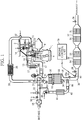
- FIG. 1 is a schematic configuration view of an intake exhaust system of a diesel engine (hereinafter referred to as an engine 1) according to an embodiment to which an exhaust gas purifying apparatus of the present invention is applied.
- the engine 1 is mounted on a vehicle as a drive source and is a multi-cylinder in-cylinder direct injection type engine (for example, a common rail diesel engine) including a turbocharger 23. More specifically, the engine 1 is configured such that a high pressure fuel accumulated in a common rail 2 is supplied to a fuel injection nozzle 3 of each cylinder and the fuel can be injected from the fuel injection nozzle 3 into a combustion chamber 4 of each cylinder at any injection timing and injection quantity.
- a multi-cylinder in-cylinder direct injection type engine for example, a common rail diesel engine
- turbocharger 23 turbocharger 23
- the engine 1 is configured such that a high pressure fuel accumulated in a common rail 2 is supplied to a fuel injection nozzle 3 of each cylinder and the fuel can be injected from the fuel injection nozzle 3 into a combustion chamber 4 of each cylinder at any injection timing and injection quantity.
- An up and down slidable piston 5 is provided in each cylinder of the engine 1.
- the piston 5 is coupled to a crankshaft 6 through a con rod.
- a flywheel is provided at one end portion of the crankshaft 6.
- the combustion chamber 4 communicates with an intake port 7 and an exhaust port 8.
- the intake port 7 includes an intake valve 9 for performing communication and blocking between the combustion chamber 4 and the intake port 7.
- the exhaust port 8 includes an exhaust valve 10 for performing communication and blocking between the combustion chamber 4 and the exhaust port 8.
- An intake manifold 11 for distributing the intake air to each cylinder is provided upstream of the intake port 7 so as to communicate with the intake port 7.
- An exhaust manifold 12 for collecting the exhaust gas discharged from each cylinder is provided downstream of the exhaust port 8 so as to communicate with the exhaust port 8.
- a high-pressure exhaust gas recirculation passage 15 for returning some of the exhaust gases back to the intake, namely, for introducing high-temperature high-pressure exhaust gases into the intake is provided between the intake manifold 11 and the exhaust manifold 12.
- An exhaust gas recirculation valve 16 for adjusting the amount of high-temperature high-pressure exhaust gas to be returned to the intake is interposedly provided at the high-pressure exhaust gas recirculation passage 15.
- An exhaust gas recirculation cooler 17 for cooling the exhaust gas to be introduced into the intake manifold 11 is provided at the high-pressure exhaust gas recirculation passage 15.
- the intake manifold 11 is connected to an intake pipe 20 as an intake passage.
- the intake pipe 20 includes, in order from the upstream side to the intake manifold 11, an air cleaner 21 for removing dust in fresh air, an electronic control throttle valve 22 for adjusting the flow rate of the low-pressure exhaust gas introduced from a low-pressure exhaust gas recirculation passage 45 to be described later while adjusting the flow rate of the fresh air, a compressor 24 of the turbocharger 23, an intercooler 25 for cooling the intake air compressed by the compressor 24 to a high temperature, and an electronic control throttle valve 27 for adjusting the flow rate of the exhaust gas introduced from the high-pressure exhaust gas recirculation passage 15.
- An exhaust pipe 30 as an exhaust passage downstream of the exhaust manifold 12 includes, in order from the upstream side, a turbine 31 of the turbocharger 23, an oxidation catalyst 32 for oxidizing oxidizable components in the exhaust gas, a diesel particulate filter 33 for collecting and burning particulate matter mainly composed of graphite in the exhaust gas, and a selective reduction catalyst 34 (exhaust gas purifying catalyst) for reducing and purifying nitrogen oxides (hereinafter referred to as NOx) in the exhaust gas using ammonia.
- the oxidation catalyst 32 and the diesel particulate filter 33 are housed in the same casing 35 and are disposed in an engine room of the vehicle.
- the selective reduction catalyst 34 is divided into four portions, which are arranged two by two in series in casings 36 and 37 and are disposed under the floor of the vehicle.
- a urea water injector 40 (reducing agent supply unit) for injecting and supplying urea water is disposed in the exhaust pipe 30 between the diesel particulate filter 33 and the selective reduction catalyst 34 located most upstream.
- Urea water is supplied to the urea water injector 40 from an unillustrated urea water tank mounted on the vehicle.
- An injection position of the urea water injector 40 is set so that the urea water injected from the urea water injector 40 into the exhaust pipe 30 is sufficiently hydrolyzed by exhaust heat to generate ammonia so as to reach the selective reduction catalyst 34.
- a low-pressure exhaust gas recirculation passage 45 (exhaust gas recirculation passage) is provided so as to communicate the intake pipe 20 between an electronic control throttle valve 22 and the compressor 24 of the turbocharger 23 with the exhaust pipe 30 between the diesel particulate filter 33 and the urea water injector 40.
- the low-pressure exhaust gas recirculation passage 45 has a function to introduce (recirculate), into the intake, some of the low-temperature low-pressure exhaust gases passing through the turbine 31, the oxidation catalyst 32, and the diesel particulate filter 33.
- the low-pressure exhaust gas recirculation passage 45 includes an exhaust gas recirculation filter 46 for removing foreign matter from the exhaust gas to recirculate to the intake, an exhaust gas recirculation cooler 47 for cooling the exhaust gas to recirculate, and an exhaust gas recirculation valve 48 (opening and closing unit) for opening and closing the low-pressure exhaust gas recirculation passage 45.
- An intake air temperature sensor 50 for detecting the temperature of the intake air (fresh air) is provided in the intake pipe 20 between the air cleaner 21 and the electronic control throttle valve 22.
- the intake manifold 11 includes an intake air temperature sensor 51 for detecting the temperature of the intake air flowing into the combustion chamber 4 of the engine 1 and an oxygen concentration sensor 52 for detecting the oxygen concentration in the intake air.
- An oxygen concentration sensor 53 for detecting the oxygen concentration in the exhaust gas is provided in the exhaust pipe 30 between the turbine 31 and the oxidation catalyst 32.
- An exhaust gas temperature sensor 54 for detecting the temperature of the exhaust gas flowing into the oxidation catalyst 32 is provided upstream of the oxidation catalyst 32 of the casing 35.
- An exhaust gas temperature sensor 55 for detecting the temperature of the exhaust gas flowing from the oxidation catalyst 32 is provided between the oxidation catalyst 32 and the diesel particulate filter 33 in the casing 35.
- an exhaust gas temperature sensor 56 for detecting the temperature of the exhaust gas flowing from the diesel particulate filter 33 is provided downstream of the diesel particulate filter 33 of the casing 35.
- An NOx sensor 57 for detecting NOx concentration in the exhaust gas is provided in the exhaust pipe 30 between the urea water injector 40 and an exhaust gas introduction section 45a of the low-pressure exhaust gas recirculation passage 45 for introducing the exhaust gas from the exhaust pipe 30.
- An exhaust gas temperature sensor 58 for detecting the temperature of the exhaust gas between the urea water injector 40 and the selective reduction catalyst 34 is provided in the exhaust pipe 30 near the urea water injector 40.
- An NOx sensor 59 for detecting NOx concentration in the exhaust gas flowing out of the most downstream selective reduction catalyst 34 is provided in the exhaust pipe 30 downstream of the selective reduction catalyst 34 located most downstream.
- An engine control unit 70 (reducing agent supply control unit and reducing agent supply regulating unit) is electrically connected to various sensors including the intake air temperature sensors 50 and 51, the oxygen concentration sensors 52 and 53, the exhaust gas temperature sensors 54, 55, 56, and 58, the NOx sensors 57 and 59, as well as various devices including the fuel injection nozzle 3, the electronic control throttle valves 22 and 27, the exhaust gas recirculation valves 16 and 48, and the urea water injector 40.
- the engine control unit 70 is configured to include input/output devices, storage devices (ROM, RAM, nonvolatile RAM, etc.,), timers, the central processing unit (CPU), and the like.
- the engine control unit 70 receives information such as detection information and the accelerator operation amount information from the aforementioned sensors, and based on the various information, calculates the fuel injection amount, the fuel injection timing, the opening degree of the electronic control throttle valves 22 and 27, and the exhaust gas recirculation valves 16 and 48, the urea water injection amount, and the urea water injection timing, thereby to perform the operation control on the various devices and perform the operation control on the engine 1.
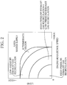
- FIG. 2 is explanatory drawing illustrating a use region of the exhaust gas purifying apparatus.
- the engine control unit 70 performs three exhaust gas purifying apparatuses: high-pressure exhaust gas recirculation by the high-pressure exhaust gas recirculation passage 15, low-pressure exhaust gas recirculation by the low-pressure exhaust gas recirculation passage 45, and exhaust gas purification in the selective reduction catalyst 34 by the urea water supply.
- only exhaust gas purification by the high-pressure exhaust gas recirculation is performed in the low-load low-speed region
- only exhaust gas purification by the low-pressure exhaust gas recirculation is performed in the medium-load medium-speed region
- only exhaust gas purification by the urea water supply is performed in the high-load high-speed region (second operating region).
- a region using both the high-pressure exhaust gas recirculation and the low-pressure exhaust gas recirculation is provided between the low-load low-speed region and the medium-load medium-speed region.
- an intermediate region (first operating region) using both the low-pressure exhaust gas recirculation and the urea water supply is provided between the medium-load medium-speed region and high-load high-speed region.
- the engine control unit 70 performs a control of stopping injection and supply of the urea water from the urea water injector 40 for a predetermined time when the operating state of the engine 1 transits from the high-load high-speed region to the intermediate region.
- the exhaust pipe 30 downstream of the diesel particulate filter 33 communicates with the intake pipe 20 between the electronic control throttle valve 22 and the compressor 24 of the turbocharger 23 through the low-pressure exhaust gas recirculation passage 45.
- the exhaust gas recirculation valve 48 switches from the closed state to the open state.
- the exhaust gas introduction section 45a serving as an entrance of the low-pressure exhaust gas recirculation passage 45 may be under a negative pressure.
- the exhaust gas may flow back and flow into the low-pressure exhaust gas recirculation passage 45, resulting in that the urea water following the flowed back exhaust gas may flow into the low-pressure exhaust gas recirculation passage 45.
- the present embodiment stops the supply of the urea water for a predetermined time, and hence can prevent the urea water from flowing into the low-pressure exhaust gas recirculation passage 45 even if the exhaust gas flows back and flows into the low-pressure exhaust gas recirculation passage 45.
- the prevention of the urea water from flowing into the low-pressure exhaust gas recirculation passage 45 can prevent urea from precipitating from the urea water in the low-pressure exhaust gas recirculation passage 45 and depositing in the low-pressure exhaust gas recirculation passage 45.
- the low-pressure exhaust gas recirculation passage 45 includes the exhaust gas recirculation cooler 47 and the exhaust gas recirculation filter 46.
- the prevention can also prevent urea from depositing on these devices and prevent these devices from failing.
- the prevention can also prevent reduction in recirculation rate of the low-pressure exhaust gas due to an increase in passing resistance by deposit of the urea in the low-pressure exhaust gas recirculation passage 45.
- the prevention can also prevent the urea water from passing through the low-pressure exhaust gas recirculation passage 45 and flowing into the intake pipe 20, and hence can protect the intake pipe 20.
- the aforementioned embodiment regulates the injection of the urea water from the urea water injector 40, but when the exhaust gas recirculation valve 48 is switches from the closed state to the open state, control may be performed so as to regulate the injection of the urea water from the urea water injector 40.
- confirmation is made in advance of the operating state of the engine 1 where the exhaust gas introduction section 45a of the low-pressure exhaust gas recirculation passage 45 is under a negative pressure, and in the operating state, the injection of the urea water may start.
- the operating state of the engine 1 where the exhaust gas introduction section 45a is under a negative pressure is a state where pulsation occurs in the exhaust gas, and is assumed to be a transient operating state.
- the present invention is not limited to the aforementioned embodiment, but may be widely applied to an exhaust gas purifying apparatus of an engine including both an exhaust gas recirculation passage and an apparatus for supplying a reducing agent to an exhaust gas and purifying the exhaust gas in the exhaust gas purifying catalyst.
Landscapes
- Engineering & Computer Science (AREA)
- Chemical & Material Sciences (AREA)
- Combustion & Propulsion (AREA)
- Mechanical Engineering (AREA)
- General Engineering & Computer Science (AREA)
- Chemical Kinetics & Catalysis (AREA)
- Health & Medical Sciences (AREA)
- Toxicology (AREA)
- Exhaust Gas After Treatment (AREA)
- Output Control And Ontrol Of Special Type Engine (AREA)
- Processes For Solid Components From Exhaust (AREA)
Claims (4)
- Appareil de purification de gaz d'échappement d'un moteur comprenant :une unité d'alimentation en agent réducteur (40) qui est prévue dans un passage d'échappement (30) du moteur (1) présentant un turbocompresseur (23), et qui fournit un agent réducteur dans le passage d'échappement (30) ;un catalyseur de purification de gaz d'échappement (34) qui est prévu dans le passage d'échappement (30) sur un côté en aval de l'unité d'alimentation en agent réducteur (40), et qui réduit et purifie l'oxyde d'azote contenu dans un gaz d'échappement dans le passage d'échappement (30) au moyen de l'agent réducteur fourni à partir de l'unité d'alimentation en agent réducteur (40) ;une unité de commande d'alimentation en agent réducteur (70) qui commande le fonctionnement de l'unité d'alimentation en agent réducteur (40) ;un filtre (33) qui est prévu dans le passage d'échappement (30) plus près d'un côté aval qu'une turbine (31) du turbocompresseur (23), qui comprend l'unité d'alimentation en agent réducteur (40) entre le filtre (33) et le catalyseur de purification du gaz d'échappement (34), et qui collecte et brûle la matière particulaire composée principalement de graphite contenue dans le gaz d'échappement ; etun passage de recirculation de gaz d'échappement (45) qui introduit le gaz d'échappement issu du passage d'échappement (30) entre le filtre (33) et une position d'alimentation de l'agent réducteur issu de l'unité d'alimentation en agent réducteur (40) et assure la recirculation du gaz d'échappement entre un papillon des gaz (22) d'un passage d'admission (20) du moteur (1) et un compresseur (24) du turbocompresseur (23) et une unité d'ouverture et de fermeture qui ouvre et ferme le passage de recirculation de gaz d'échappement sur la base de l'état de fonctionnement du moteur, caractérisé en ce qu'il comprend en outreune unité de régulation d'alimentation en agent réducteur (70) qui interrompt l'alimentation en agent réducteur à partir de l'unité d'alimentation en agent réducteur (40) dans un état de fonctionnement du moteur (1) où une section d'introduction de gaz d'échappement (45a) du passage de recyclage de gaz d'échappement (45) est soumise à une pression négative lorsque l'unité d'ouverture et de fermeture est commutée d'un état fermé vers un état ouvert et le gaz d'échappement reflue lorsque le gaz d'échappement est recyclé à travers le passage de recyclage de gaz d'échappement (45).
- Appareil de purification de gaz d'échappement du moteur selon la revendication 1, caractérisé en ce qu'il comprend en outre
une unité d'ouverture et de fermeture (48) qui ouvre et ferme le passage de recyclage de gaz d'échappement (45) sur la base de l'état de fonctionnement du moteur (1), dans lequel
l'unité de régulation d'alimentation en agent réducteur (70) interrompt l'alimentation en agent réducteur de l'unité d'alimentation en agent réducteur (40) lorsque l'unité d'ouverture et de fermeture (48) est commutée d'un état fermé à un état ouvert. - Appareil de purification de gaz d'échappement du moteur selon la revendication 1 ou 2, caractérisé en ce que
le moteur (1) possède une première région de fonctionnement du moteur (1) qui est définie sur la base de l'état de fonctionnement du moteur (1), et qui utilise à la fois la recirculation du gaz d'échappement à travers le passage de recirculation de gaz d'échappement (45) et l'alimentation en agent réducteur, et
l'unité de régulation d'alimentation en agent réducteur (70) interrompt l'alimentation en agent réducteur à partir de l'unité d'alimentation en agent réducteur (40) lorsque l'état de fonctionnement du moteur (1) transite de la région à charge élevée et vitesse élevée à la première région de fonctionnement. - Appareil de purification de gaz d'échappement du moteur selon l'une quelconque des revendications 1 à 3, caractérisé en ce que le moteur (1) comporte
une première région de fonctionnement configurée pour utiliser à la fois la recirculation du gaz d'échappement à travers le passage de recirculation de gaz d'échappement (45) et l'alimentation en agent réducteur ; et
une seconde région de fonctionnement qui est une région à rotation plus élevée ou charge plus élevée que la première région de fonctionnement, et dans laquelle le gaz d'échappement n'est pas recirculé à travers le passage de recirculation de gaz d'échappement (45) mais le gaz réducteur est fourni, dans lequel
l'unité de régulation d'alimentation en agent réducteur (70) interrompt l'alimentation en agent réducteur à partir de l'unité d'alimentation en agent réducteur (40) lorsque la région de fonctionnement du moteur (1) transite de la seconde région de fonctionnement à la première région de fonctionnement.
Applications Claiming Priority (2)
| Application Number | Priority Date | Filing Date | Title |
|---|---|---|---|
| JP2013026461A JP6115711B2 (ja) | 2013-02-14 | 2013-02-14 | エンジンの排気浄化装置 |
| PCT/JP2014/050800 WO2014125869A1 (fr) | 2013-02-14 | 2014-01-17 | Dispositif de purification de gaz d'échappement de moteur |
Publications (3)
| Publication Number | Publication Date |
|---|---|
| EP2957738A1 EP2957738A1 (fr) | 2015-12-23 |
| EP2957738A4 EP2957738A4 (fr) | 2016-10-26 |
| EP2957738B1 true EP2957738B1 (fr) | 2018-10-24 |
Family
ID=51353879
Family Applications (1)
| Application Number | Title | Priority Date | Filing Date |
|---|---|---|---|
| EP14751687.6A Not-in-force EP2957738B1 (fr) | 2013-02-14 | 2014-01-17 | Dispositif de purification de gaz d'échappement de moteur |
Country Status (3)
| Country | Link |
|---|---|
| EP (1) | EP2957738B1 (fr) |
| JP (1) | JP6115711B2 (fr) |
| WO (1) | WO2014125869A1 (fr) |
Family Cites Families (5)
| Publication number | Priority date | Publication date | Assignee | Title |
|---|---|---|---|---|
| JP4345377B2 (ja) * | 2003-06-30 | 2009-10-14 | トヨタ自動車株式会社 | 内燃機関の排気浄化装置 |
| JP2008064063A (ja) * | 2006-09-11 | 2008-03-21 | Toyota Motor Corp | 内燃機関の排気浄化装置 |
| JP4730336B2 (ja) * | 2007-05-22 | 2011-07-20 | トヨタ自動車株式会社 | 内燃機関の排気再循環制御装置 |
| US8635853B2 (en) * | 2008-01-25 | 2014-01-28 | Caterpillar Inc. | Exhaust reduction system having oxygen and temperature control |
| DE102009057799A1 (de) * | 2009-12-10 | 2011-06-16 | Volkswagen Ag | Kraftfahrzeug mit einem abgasturboaufgeladenen Dieselmotor, einem Schaltgetriebe und einem Abgasrückführungssystem |
-
2013
- 2013-02-14 JP JP2013026461A patent/JP6115711B2/ja active Active
-
2014
- 2014-01-17 EP EP14751687.6A patent/EP2957738B1/fr not_active Not-in-force
- 2014-01-17 WO PCT/JP2014/050800 patent/WO2014125869A1/fr not_active Ceased
Non-Patent Citations (1)
| Title |
|---|
| None * |
Also Published As
| Publication number | Publication date |
|---|---|
| EP2957738A1 (fr) | 2015-12-23 |
| JP6115711B2 (ja) | 2017-04-19 |
| JP2014156784A (ja) | 2014-08-28 |
| EP2957738A4 (fr) | 2016-10-26 |
| WO2014125869A1 (fr) | 2014-08-21 |
Similar Documents
| Publication | Publication Date | Title |
|---|---|---|
| EP2636879B1 (fr) | Dispositif de diagnostic de défaut pour système egr | |
| US9020739B2 (en) | Control device for internal combustion engine having an external exhaust gas recirculation system | |
| US9624874B2 (en) | Exhaust gas recirculation apparatus and control method therefor | |
| RU2569397C2 (ru) | Способ эксплуатации бензинового двигателя с наддувом (варианты) и бензиновый двигатель | |
| JP5332674B2 (ja) | 内燃機関の排気再循環装置 | |
| EP2957737B1 (fr) | Dispositif de purification de gaz d'échappement de moteur | |
| KR102518588B1 (ko) | 응축수 배출을 위한 엔진 시스템 및 이를 이용한 제어 방법 | |
| EP2527628B1 (fr) | Dispositif de commande d'un moteur à combustion interne | |
| JP6319561B2 (ja) | 排気浄化システム | |
| JP6108078B2 (ja) | エンジンの排気浄化装置 | |
| EP2957738B1 (fr) | Dispositif de purification de gaz d'échappement de moteur | |
| JP3743232B2 (ja) | 内燃機関の白煙排出抑制装置 | |
| JP5823842B2 (ja) | ターボチャージャ付多気筒内燃機関の排気還流装置 | |
| JP2015059560A (ja) | Egr装置及び排気ガス還流方法 | |
| JP2015101972A (ja) | エンジンの排気環流装置 | |
| JP5915856B2 (ja) | 内燃機関の排気浄化装置 | |
| JP4206934B2 (ja) | 内燃機関用過給システム | |
| JP2012167562A (ja) | ディーゼルエンジン | |
| JP5915855B2 (ja) | 内燃機関の排気浄化装置 | |
| JP2010185351A (ja) | 排気還流装置 | |
| JP2010031750A (ja) | 内燃機関の制御装置 | |
| JPH11287126A (ja) | 過給機付きエンジンの過給圧制御方法および装置 | |
| JP2010133327A (ja) | 内燃機関の排気浄化装置 | |
| JP6116047B2 (ja) | ターボ過給機付エンジン | |
| JP2013083204A (ja) | ディーゼルエンジン |
Legal Events
| Date | Code | Title | Description |
|---|---|---|---|
| PUAI | Public reference made under article 153(3) epc to a published international application that has entered the european phase |
Free format text: ORIGINAL CODE: 0009012 |
|
| 17P | Request for examination filed |
Effective date: 20150831 |
|
| AK | Designated contracting states |
Kind code of ref document: A1 Designated state(s): AL AT BE BG CH CY CZ DE DK EE ES FI FR GB GR HR HU IE IS IT LI LT LU LV MC MK MT NL NO PL PT RO RS SE SI SK SM TR |
|
| AX | Request for extension of the european patent |
Extension state: BA ME |
|
| DAX | Request for extension of the european patent (deleted) | ||
| A4 | Supplementary search report drawn up and despatched |
Effective date: 20160927 |
|
| RIC1 | Information provided on ipc code assigned before grant |
Ipc: F01N 3/24 20060101ALI20160921BHEP Ipc: F01N 3/08 20060101AFI20160921BHEP Ipc: F02D 21/08 20060101ALI20160921BHEP |
|
| STAA | Information on the status of an ep patent application or granted ep patent |
Free format text: STATUS: EXAMINATION IS IN PROGRESS |
|
| 17Q | First examination report despatched |
Effective date: 20170511 |
|
| REG | Reference to a national code |
Ref country code: DE Ref legal event code: R079 Ref document number: 602014034667 Country of ref document: DE Free format text: PREVIOUS MAIN CLASS: F01N0003080000 Ipc: F02M0026000000 |
|
| RIC1 | Information provided on ipc code assigned before grant |
Ipc: F01N 3/20 20060101AFI20171024BHEP Ipc: F01N 13/00 20100101ALI20171024BHEP Ipc: F01N 3/035 20060101ALI20171024BHEP |
|
| RIC1 | Information provided on ipc code assigned before grant |
Ipc: F01N 13/00 20100101ALI20171102BHEP Ipc: F01N 3/20 20060101ALI20171102BHEP Ipc: F01N 3/035 20060101ALI20171102BHEP Ipc: F02M 26/00 20160101AFI20171102BHEP |
|
| GRAP | Despatch of communication of intention to grant a patent |
Free format text: ORIGINAL CODE: EPIDOSNIGR1 |
|
| STAA | Information on the status of an ep patent application or granted ep patent |
Free format text: STATUS: GRANT OF PATENT IS INTENDED |
|
| INTG | Intention to grant announced |
Effective date: 20180518 |
|
| GRAS | Grant fee paid |
Free format text: ORIGINAL CODE: EPIDOSNIGR3 |
|
| GRAA | (expected) grant |
Free format text: ORIGINAL CODE: 0009210 |
|
| STAA | Information on the status of an ep patent application or granted ep patent |
Free format text: STATUS: THE PATENT HAS BEEN GRANTED |
|
| AK | Designated contracting states |
Kind code of ref document: B1 Designated state(s): AL AT BE BG CH CY CZ DE DK EE ES FI FR GB GR HR HU IE IS IT LI LT LU LV MC MK MT NL NO PL PT RO RS SE SI SK SM TR |
|
| REG | Reference to a national code |
Ref country code: CH Ref legal event code: EP |
|
| REG | Reference to a national code |
Ref country code: IE Ref legal event code: FG4D |
|
| REG | Reference to a national code |
Ref country code: AT Ref legal event code: REF Ref document number: 1056943 Country of ref document: AT Kind code of ref document: T Effective date: 20181115 |
|
| REG | Reference to a national code |
Ref country code: DE Ref legal event code: R096 Ref document number: 602014034667 Country of ref document: DE |
|
| REG | Reference to a national code |
Ref country code: NL Ref legal event code: MP Effective date: 20181024 |
|
| REG | Reference to a national code |
Ref country code: LT Ref legal event code: MG4D |
|
| REG | Reference to a national code |
Ref country code: AT Ref legal event code: MK05 Ref document number: 1056943 Country of ref document: AT Kind code of ref document: T Effective date: 20181024 |
|
| PG25 | Lapsed in a contracting state [announced via postgrant information from national office to epo] |
Ref country code: NL Free format text: LAPSE BECAUSE OF FAILURE TO SUBMIT A TRANSLATION OF THE DESCRIPTION OR TO PAY THE FEE WITHIN THE PRESCRIBED TIME-LIMIT Effective date: 20181024 |
|
| PG25 | Lapsed in a contracting state [announced via postgrant information from national office to epo] |
Ref country code: AT Free format text: LAPSE BECAUSE OF FAILURE TO SUBMIT A TRANSLATION OF THE DESCRIPTION OR TO PAY THE FEE WITHIN THE PRESCRIBED TIME-LIMIT Effective date: 20181024 Ref country code: NO Free format text: LAPSE BECAUSE OF FAILURE TO SUBMIT A TRANSLATION OF THE DESCRIPTION OR TO PAY THE FEE WITHIN THE PRESCRIBED TIME-LIMIT Effective date: 20190124 Ref country code: ES Free format text: LAPSE BECAUSE OF FAILURE TO SUBMIT A TRANSLATION OF THE DESCRIPTION OR TO PAY THE FEE WITHIN THE PRESCRIBED TIME-LIMIT Effective date: 20181024 Ref country code: LT Free format text: LAPSE BECAUSE OF FAILURE TO SUBMIT A TRANSLATION OF THE DESCRIPTION OR TO PAY THE FEE WITHIN THE PRESCRIBED TIME-LIMIT Effective date: 20181024 Ref country code: LV Free format text: LAPSE BECAUSE OF FAILURE TO SUBMIT A TRANSLATION OF THE DESCRIPTION OR TO PAY THE FEE WITHIN THE PRESCRIBED TIME-LIMIT Effective date: 20181024 Ref country code: HR Free format text: LAPSE BECAUSE OF FAILURE TO SUBMIT A TRANSLATION OF THE DESCRIPTION OR TO PAY THE FEE WITHIN THE PRESCRIBED TIME-LIMIT Effective date: 20181024 Ref country code: PL Free format text: LAPSE BECAUSE OF FAILURE TO SUBMIT A TRANSLATION OF THE DESCRIPTION OR TO PAY THE FEE WITHIN THE PRESCRIBED TIME-LIMIT Effective date: 20181024 Ref country code: BG Free format text: LAPSE BECAUSE OF FAILURE TO SUBMIT A TRANSLATION OF THE DESCRIPTION OR TO PAY THE FEE WITHIN THE PRESCRIBED TIME-LIMIT Effective date: 20190124 Ref country code: IS Free format text: LAPSE BECAUSE OF FAILURE TO SUBMIT A TRANSLATION OF THE DESCRIPTION OR TO PAY THE FEE WITHIN THE PRESCRIBED TIME-LIMIT Effective date: 20190224 Ref country code: FI Free format text: LAPSE BECAUSE OF FAILURE TO SUBMIT A TRANSLATION OF THE DESCRIPTION OR TO PAY THE FEE WITHIN THE PRESCRIBED TIME-LIMIT Effective date: 20181024 |
|
| PG25 | Lapsed in a contracting state [announced via postgrant information from national office to epo] |
Ref country code: SE Free format text: LAPSE BECAUSE OF FAILURE TO SUBMIT A TRANSLATION OF THE DESCRIPTION OR TO PAY THE FEE WITHIN THE PRESCRIBED TIME-LIMIT Effective date: 20181024 Ref country code: GR Free format text: LAPSE BECAUSE OF FAILURE TO SUBMIT A TRANSLATION OF THE DESCRIPTION OR TO PAY THE FEE WITHIN THE PRESCRIBED TIME-LIMIT Effective date: 20190125 Ref country code: RS Free format text: LAPSE BECAUSE OF FAILURE TO SUBMIT A TRANSLATION OF THE DESCRIPTION OR TO PAY THE FEE WITHIN THE PRESCRIBED TIME-LIMIT Effective date: 20181024 Ref country code: AL Free format text: LAPSE BECAUSE OF FAILURE TO SUBMIT A TRANSLATION OF THE DESCRIPTION OR TO PAY THE FEE WITHIN THE PRESCRIBED TIME-LIMIT Effective date: 20181024 Ref country code: PT Free format text: LAPSE BECAUSE OF FAILURE TO SUBMIT A TRANSLATION OF THE DESCRIPTION OR TO PAY THE FEE WITHIN THE PRESCRIBED TIME-LIMIT Effective date: 20190224 |
|
| RAP2 | Party data changed (patent owner data changed or rights of a patent transferred) |
Owner name: MITSUBISHI JIDOSHA KOGYO KABUSHIKI KAISHA |
|
| REG | Reference to a national code |
Ref country code: DE Ref legal event code: R097 Ref document number: 602014034667 Country of ref document: DE |
|
| PG25 | Lapsed in a contracting state [announced via postgrant information from national office to epo] |
Ref country code: DK Free format text: LAPSE BECAUSE OF FAILURE TO SUBMIT A TRANSLATION OF THE DESCRIPTION OR TO PAY THE FEE WITHIN THE PRESCRIBED TIME-LIMIT Effective date: 20181024 Ref country code: IT Free format text: LAPSE BECAUSE OF FAILURE TO SUBMIT A TRANSLATION OF THE DESCRIPTION OR TO PAY THE FEE WITHIN THE PRESCRIBED TIME-LIMIT Effective date: 20181024 Ref country code: CZ Free format text: LAPSE BECAUSE OF FAILURE TO SUBMIT A TRANSLATION OF THE DESCRIPTION OR TO PAY THE FEE WITHIN THE PRESCRIBED TIME-LIMIT Effective date: 20181024 |
|
| PG25 | Lapsed in a contracting state [announced via postgrant information from national office to epo] |
Ref country code: EE Free format text: LAPSE BECAUSE OF FAILURE TO SUBMIT A TRANSLATION OF THE DESCRIPTION OR TO PAY THE FEE WITHIN THE PRESCRIBED TIME-LIMIT Effective date: 20181024 Ref country code: SM Free format text: LAPSE BECAUSE OF FAILURE TO SUBMIT A TRANSLATION OF THE DESCRIPTION OR TO PAY THE FEE WITHIN THE PRESCRIBED TIME-LIMIT Effective date: 20181024 Ref country code: RO Free format text: LAPSE BECAUSE OF FAILURE TO SUBMIT A TRANSLATION OF THE DESCRIPTION OR TO PAY THE FEE WITHIN THE PRESCRIBED TIME-LIMIT Effective date: 20181024 Ref country code: SK Free format text: LAPSE BECAUSE OF FAILURE TO SUBMIT A TRANSLATION OF THE DESCRIPTION OR TO PAY THE FEE WITHIN THE PRESCRIBED TIME-LIMIT Effective date: 20181024 Ref country code: MC Free format text: LAPSE BECAUSE OF FAILURE TO SUBMIT A TRANSLATION OF THE DESCRIPTION OR TO PAY THE FEE WITHIN THE PRESCRIBED TIME-LIMIT Effective date: 20181024 |
|
| PLBE | No opposition filed within time limit |
Free format text: ORIGINAL CODE: 0009261 |
|
| REG | Reference to a national code |
Ref country code: CH Ref legal event code: PL |
|
| STAA | Information on the status of an ep patent application or granted ep patent |
Free format text: STATUS: NO OPPOSITION FILED WITHIN TIME LIMIT |
|
| GBPC | Gb: european patent ceased through non-payment of renewal fee |
Effective date: 20190124 |
|
| PG25 | Lapsed in a contracting state [announced via postgrant information from national office to epo] |
Ref country code: LU Free format text: LAPSE BECAUSE OF NON-PAYMENT OF DUE FEES Effective date: 20190117 |
|
| 26N | No opposition filed |
Effective date: 20190725 |
|
| REG | Reference to a national code |
Ref country code: BE Ref legal event code: MM Effective date: 20190131 |
|
| REG | Reference to a national code |
Ref country code: IE Ref legal event code: MM4A |
|
| PG25 | Lapsed in a contracting state [announced via postgrant information from national office to epo] |
Ref country code: SI Free format text: LAPSE BECAUSE OF FAILURE TO SUBMIT A TRANSLATION OF THE DESCRIPTION OR TO PAY THE FEE WITHIN THE PRESCRIBED TIME-LIMIT Effective date: 20181024 |
|
| PG25 | Lapsed in a contracting state [announced via postgrant information from national office to epo] |
Ref country code: BE Free format text: LAPSE BECAUSE OF NON-PAYMENT OF DUE FEES Effective date: 20190131 |
|
| PG25 | Lapsed in a contracting state [announced via postgrant information from national office to epo] |
Ref country code: CH Free format text: LAPSE BECAUSE OF NON-PAYMENT OF DUE FEES Effective date: 20190131 Ref country code: GB Free format text: LAPSE BECAUSE OF NON-PAYMENT OF DUE FEES Effective date: 20190124 Ref country code: LI Free format text: LAPSE BECAUSE OF NON-PAYMENT OF DUE FEES Effective date: 20190131 |
|
| PG25 | Lapsed in a contracting state [announced via postgrant information from national office to epo] |
Ref country code: IE Free format text: LAPSE BECAUSE OF NON-PAYMENT OF DUE FEES Effective date: 20190117 |
|
| PGFP | Annual fee paid to national office [announced via postgrant information from national office to epo] |
Ref country code: FR Payment date: 20191216 Year of fee payment: 7 |
|
| PG25 | Lapsed in a contracting state [announced via postgrant information from national office to epo] |
Ref country code: TR Free format text: LAPSE BECAUSE OF FAILURE TO SUBMIT A TRANSLATION OF THE DESCRIPTION OR TO PAY THE FEE WITHIN THE PRESCRIBED TIME-LIMIT Effective date: 20181024 |
|
| PGFP | Annual fee paid to national office [announced via postgrant information from national office to epo] |
Ref country code: DE Payment date: 20200107 Year of fee payment: 7 |
|
| PG25 | Lapsed in a contracting state [announced via postgrant information from national office to epo] |
Ref country code: MT Free format text: LAPSE BECAUSE OF NON-PAYMENT OF DUE FEES Effective date: 20190117 |
|
| PG25 | Lapsed in a contracting state [announced via postgrant information from national office to epo] |
Ref country code: CY Free format text: LAPSE BECAUSE OF FAILURE TO SUBMIT A TRANSLATION OF THE DESCRIPTION OR TO PAY THE FEE WITHIN THE PRESCRIBED TIME-LIMIT Effective date: 20181024 |
|
| PG25 | Lapsed in a contracting state [announced via postgrant information from national office to epo] |
Ref country code: HU Free format text: LAPSE BECAUSE OF FAILURE TO SUBMIT A TRANSLATION OF THE DESCRIPTION OR TO PAY THE FEE WITHIN THE PRESCRIBED TIME-LIMIT; INVALID AB INITIO Effective date: 20140117 |
|
| REG | Reference to a national code |
Ref country code: DE Ref legal event code: R119 Ref document number: 602014034667 Country of ref document: DE |
|
| PG25 | Lapsed in a contracting state [announced via postgrant information from national office to epo] |
Ref country code: FR Free format text: LAPSE BECAUSE OF NON-PAYMENT OF DUE FEES Effective date: 20210131 |
|
| PG25 | Lapsed in a contracting state [announced via postgrant information from national office to epo] |
Ref country code: DE Free format text: LAPSE BECAUSE OF NON-PAYMENT OF DUE FEES Effective date: 20210803 |
|
| PG25 | Lapsed in a contracting state [announced via postgrant information from national office to epo] |
Ref country code: MK Free format text: LAPSE BECAUSE OF FAILURE TO SUBMIT A TRANSLATION OF THE DESCRIPTION OR TO PAY THE FEE WITHIN THE PRESCRIBED TIME-LIMIT Effective date: 20181024 |