EP2957782A2 - Chariot de guidage pour une section de guidage d'un corps roulant saisissant l'élément d'insertion de chemin de roulement - Google Patents
Chariot de guidage pour une section de guidage d'un corps roulant saisissant l'élément d'insertion de chemin de roulement Download PDFInfo
- Publication number
- EP2957782A2 EP2957782A2 EP15167455.3A EP15167455A EP2957782A2 EP 2957782 A2 EP2957782 A2 EP 2957782A2 EP 15167455 A EP15167455 A EP 15167455A EP 2957782 A2 EP2957782 A2 EP 2957782A2
- Authority
- EP
- European Patent Office
- Prior art keywords
- carriage
- guide
- track
- insert
- main body
- Prior art date
- Legal status (The legal status is an assumption and is not a legal conclusion. Google has not performed a legal analysis and makes no representation as to the accuracy of the status listed.)
- Granted
Links
Images

Classifications
-
- F—MECHANICAL ENGINEERING; LIGHTING; HEATING; WEAPONS; BLASTING
- F16—ENGINEERING ELEMENTS AND UNITS; GENERAL MEASURES FOR PRODUCING AND MAINTAINING EFFECTIVE FUNCTIONING OF MACHINES OR INSTALLATIONS; THERMAL INSULATION IN GENERAL
- F16C—SHAFTS; FLEXIBLE SHAFTS; ELEMENTS OR CRANKSHAFT MECHANISMS; ROTARY BODIES OTHER THAN GEARING ELEMENTS; BEARINGS
- F16C29/00—Bearings for parts moving only linearly
- F16C29/04—Ball or roller bearings
- F16C29/06—Ball or roller bearings in which the rolling bodies circulate partly without carrying load
-
- F—MECHANICAL ENGINEERING; LIGHTING; HEATING; WEAPONS; BLASTING
- F16—ENGINEERING ELEMENTS AND UNITS; GENERAL MEASURES FOR PRODUCING AND MAINTAINING EFFECTIVE FUNCTIONING OF MACHINES OR INSTALLATIONS; THERMAL INSULATION IN GENERAL
- F16C—SHAFTS; FLEXIBLE SHAFTS; ELEMENTS OR CRANKSHAFT MECHANISMS; ROTARY BODIES OTHER THAN GEARING ELEMENTS; BEARINGS
- F16C29/00—Bearings for parts moving only linearly
- F16C29/04—Ball or roller bearings
- F16C29/06—Ball or roller bearings in which the rolling bodies circulate partly without carrying load
- F16C29/0602—Details of the bearing body or carriage or parts thereof, e.g. methods for manufacturing or assembly
- F16C29/0604—Details of the bearing body or carriage or parts thereof, e.g. methods for manufacturing or assembly of the load bearing section
- F16C29/0607—Details of the bearing body or carriage or parts thereof, e.g. methods for manufacturing or assembly of the load bearing section of parts or members for retaining the rolling elements, i.e. members to prevent the rolling elements from falling out of the bearing body or carriage
-
- F—MECHANICAL ENGINEERING; LIGHTING; HEATING; WEAPONS; BLASTING
- F16—ENGINEERING ELEMENTS AND UNITS; GENERAL MEASURES FOR PRODUCING AND MAINTAINING EFFECTIVE FUNCTIONING OF MACHINES OR INSTALLATIONS; THERMAL INSULATION IN GENERAL
- F16C—SHAFTS; FLEXIBLE SHAFTS; ELEMENTS OR CRANKSHAFT MECHANISMS; ROTARY BODIES OTHER THAN GEARING ELEMENTS; BEARINGS
- F16C29/00—Bearings for parts moving only linearly
- F16C29/04—Ball or roller bearings
- F16C29/06—Ball or roller bearings in which the rolling bodies circulate partly without carrying load
- F16C29/0633—Ball or roller bearings in which the rolling bodies circulate partly without carrying load with a bearing body defining a U-shaped carriage, i.e. surrounding a guide rail or track on three sides
- F16C29/0635—Ball or roller bearings in which the rolling bodies circulate partly without carrying load with a bearing body defining a U-shaped carriage, i.e. surrounding a guide rail or track on three sides whereby the return paths are provided as bores in a main body of the U-shaped carriage, e.g. the main body of the U-shaped carriage is a single part with end caps provided at each end
- F16C29/0638—Ball or roller bearings in which the rolling bodies circulate partly without carrying load with a bearing body defining a U-shaped carriage, i.e. surrounding a guide rail or track on three sides whereby the return paths are provided as bores in a main body of the U-shaped carriage, e.g. the main body of the U-shaped carriage is a single part with end caps provided at each end with balls
- F16C29/0642—Ball or roller bearings in which the rolling bodies circulate partly without carrying load with a bearing body defining a U-shaped carriage, i.e. surrounding a guide rail or track on three sides whereby the return paths are provided as bores in a main body of the U-shaped carriage, e.g. the main body of the U-shaped carriage is a single part with end caps provided at each end with balls with four rows of balls
- F16C29/0645—Ball or roller bearings in which the rolling bodies circulate partly without carrying load with a bearing body defining a U-shaped carriage, i.e. surrounding a guide rail or track on three sides whereby the return paths are provided as bores in a main body of the U-shaped carriage, e.g. the main body of the U-shaped carriage is a single part with end caps provided at each end with balls with four rows of balls with load directions in O-arrangement
-
- F—MECHANICAL ENGINEERING; LIGHTING; HEATING; WEAPONS; BLASTING
- F16—ENGINEERING ELEMENTS AND UNITS; GENERAL MEASURES FOR PRODUCING AND MAINTAINING EFFECTIVE FUNCTIONING OF MACHINES OR INSTALLATIONS; THERMAL INSULATION IN GENERAL
- F16C—SHAFTS; FLEXIBLE SHAFTS; ELEMENTS OR CRANKSHAFT MECHANISMS; ROTARY BODIES OTHER THAN GEARING ELEMENTS; BEARINGS
- F16C29/00—Bearings for parts moving only linearly
- F16C29/08—Arrangements for covering or protecting the ways
- F16C29/084—Arrangements for covering or protecting the ways fixed to the carriage or bearing body movable along the guide rail or track
- F16C29/088—Seals extending in the longitudinal direction of the carriage or bearing body
-
- F—MECHANICAL ENGINEERING; LIGHTING; HEATING; WEAPONS; BLASTING
- F16—ENGINEERING ELEMENTS AND UNITS; GENERAL MEASURES FOR PRODUCING AND MAINTAINING EFFECTIVE FUNCTIONING OF MACHINES OR INSTALLATIONS; THERMAL INSULATION IN GENERAL
- F16C—SHAFTS; FLEXIBLE SHAFTS; ELEMENTS OR CRANKSHAFT MECHANISMS; ROTARY BODIES OTHER THAN GEARING ELEMENTS; BEARINGS
- F16C33/00—Parts of bearings; Special methods for making bearings or parts thereof
- F16C33/30—Parts of ball or roller bearings
- F16C33/58—Raceways; Race rings
- F16C33/60—Raceways; Race rings divided or split, e.g. comprising two juxtaposed rings
-
- F—MECHANICAL ENGINEERING; LIGHTING; HEATING; WEAPONS; BLASTING
- F16—ENGINEERING ELEMENTS AND UNITS; GENERAL MEASURES FOR PRODUCING AND MAINTAINING EFFECTIVE FUNCTIONING OF MACHINES OR INSTALLATIONS; THERMAL INSULATION IN GENERAL
- F16C—SHAFTS; FLEXIBLE SHAFTS; ELEMENTS OR CRANKSHAFT MECHANISMS; ROTARY BODIES OTHER THAN GEARING ELEMENTS; BEARINGS
- F16C43/00—Assembling bearings
- F16C43/04—Assembling rolling-contact bearings
Definitions
- the invention relates to a carriage according to the preamble of claim 1.
- a carriage which is intended for use with an elongated guide rail.
- the carriage comprises four rows of spherical rolling elements, each received in an associated endless circulation channel.
- Each circulation channel comprises a support section and a return channel, which are connected to each other at both opposite ends via a respective curved deflection channel.
- the support section is bounded by a carriage track on the carriage and a rail track on the guide rail, which each extend in a longitudinal direction. All deflection channels are arranged within two separate end caps, which are fastened to the two opposite longitudinal end faces of the main body of the guide carriage.
- the separate main body made of metal, in particular made of steel, is U-shaped in cross-section.
- a raceway insert which consists of hardened steel, with two carriage tracks are provided on a raceway insert.
- a Wälzköiperhaltesteg is provided, which is integrally formed with the end caps.
- the clear width between the Wälzköiperhaltesteg and the main body in the rail track is made smaller than the diameter of the rolling elements, so that the latter can not pass through the corresponding gap.
- the advantage of the present invention is that the main body can be manufactured more cheaply.
- the grinding machining on the main body in the area of the raceway inserts is simplified.
- the guide carriage according to the invention has fewer items than the known carriage.
- a separate WälzSystem entrysteil which has a guide portion which extends in the longitudinal direction, wherein the guide portion engages behind the raceway insert.
- radially inner deflection surfaces of the deflection channel are provided on the WälzSystem involvedsteil.
- the guide portion preferably has a constant cross-sectional shape along the longitudinal direction.
- the raceway insert is preferably made of metal, in particular of hardened steel.
- the raceway insert is preferably located directly on the main body. But it can also be glued to this.
- the guide section has a first rolling body guide surface which delimits the circulation channel in the carrying section, wherein the first rolling body guide surface is circular in cross-section.
- the spherical rolling elements can thus run quietly along the first rolling body guide surface.
- the WälzSystem Entrysteil consists of plastic. Preferably, it is produced by injection molding.
- a longitudinally extending WälzERAhaltesteg which has a second WälzSystem's Colour which limits the circulation channel in the support portion such that the carriage track between the the second WälzSystem's Construction viewed in cross section is circular, wherein the clear width between the first and the second WälzSystem'sthesis in the rail track is smaller than the diameter of the rolling elements. This prevents that the rolling elements fall out of the guide carriage, if it is not mounted on the guide rail.
- the Wälzissonschreibsteg is preferably formed integrally with the end caps, wherein each part of the WälzSystemhaltestegs can be arranged on each of the two end caps.
- the main body has a flat bearing surface on which the guide section abuts, wherein the raceway insert extends between the rolling elements in the support section and the support surface.
- a shoulder is arranged on the main body at the end remote from the track insert end of the bearing surface, wherein the guide section bears against the shoulder. The step prevents the rear grip between the guide section and the raceway insert from being canceled by deformation of the guide section.
- a longitudinal sealing lip is arranged on the guide section, which is arranged so that it touches the guide rail when the guide carriage is mounted thereon.
- the longitudinal sealing lip is preferably formed integrally with the guide section.
- the Wälzköiper Resultssteil preferably consists of an elastomer, so that the longitudinal sealing lip has a particularly good sealing effect.
- the guide portion has a free surface facing away from the raceway liner, with the free surface passing into the longitudinal sealing lip without heels.
- a corresponding guide section is particularly space-saving, so that the main body in the region of the guide section is not unnecessary has to be weakened.
- the carriage has accordingly a high rigidity.
- the raceway insert has a first and a second carriage track, wherein between the first and the second carriage track, a first bearing surface is arranged on the raceway insert, wherein the raceway insert has a second bearing surface, which is arranged opposite to the first bearing surface, wherein the Width of the second bearing surface is greater than the width of the first bearing surface.
- the wider second bearing surface is used for placing the raceway insert in a grinding machine during the processing of the railroad tracks, which are preferably ground.
- the proposed design of the raceway insert the WälzSystemumcreate can be arranged at a small distance from each other. As a result, the associated guide rail can be formed with a small height, so that material is saved.
- the first and / or the second bearing surface are preferably flat, wherein they may be interrupted by a groove.
- the raceway insert in the region of the second bearing surface has a groove which extends in the longitudinal direction over the entire length of the raceway insert. About the said groove, the raceway insert is aligned during the grinding of the carriage tracks.
- the main body has a V-shaped groove having first and second planar side surfaces, the raceway liner abutting the first and second side surfaces, the rolling elements being disposed in the support portion within the straight extension of the first and second side surfaces are.
- the rolling element circulations associated with the raceway insert can consequently be arranged at a small distance from each other, without any fear of tilting of the raceway insert in the V-shaped groove.
- the bottom of the V-shaped groove is preferably rounded, the rounding diameter being substantially equal to the width of the second bearing surface.
- Fig. 1 shows an exploded view of a carriage 20 according to the invention.
- the carriage 20 comprises a main body 30 of unhardened steel, which extends in a substantially constant, U-shaped cross-sectional shape in a longitudinal direction 11.
- On the inside of the U-legs 35 each have a V-shaped groove 33 is arranged on each of which a separate raceway insert 40 is applied, which consists of hardened bearing steel.
- the two raceways 40 extend with a substantially constant cross-sectional shape in the longitudinal direction 11, wherein they each have two carriage tracks 41a; 41b, so that the guide carriage 20 a total of four rows of rolling elements (No. 21 in Fig. 2 ) Has.
- planar longitudinal end faces 31 of the main body 30 is depending on an end cap 50 with an inner longitudinal end face 55 directly.
- the two end caps 50 are identical, being made of plastic in Injection molding are made.
- a radially outer deflection surface 51 of a bent deflection channel 24 is provided in each of the two end caps 50.
- In the end cap 50 are each two associated ends of the two WälzMechest 80 are used, on which the radially inner deflection surfaces 81 of the bent deflection channels 24 are provided.
- a return channel 32 which is presently formed directly in the main body 30 in the form of a circular bore, which is provided at both ends with a countersink.
- the present invention can also be used for guide carriages in which the return channel is formed in a separate return pipe or on the outside of the main body.
- each two circular mounting holes 52 are arranged, which extend in the longitudinal direction 11.
- the mounting holes 52 are each penetrated by an associated fastening screw 26, which has an external thread end, which is screwed into an associated internal thread 36 in the main body 30.
- the internal thread 36 is arranged approximately in the region of the transition between the base 34 and an associated U-leg 35 of the main body 30, so that the two fastening screws 26 press the associated end cap 50 over the entire inner longitudinal end face 55 uniformly to the longitudinal end face of the main body 30.
- a U-shaped end seal 90 which is formed substantially as a flat plate with a constant thickness, wherein it consists of an elastomer, in particular thermoplastic ether ester elastomer (TEEE, trade name "Hytrel”) ,
- TEEE thermoplastic ether ester elastomer
- the end seal 90 is provided with an end seal lip 91 which seals against the guide rail (No. 10 in FIG Fig. 2 ) is present.
- a U-shaped stripper plate 95 which is designed in the form of a flat plate with a constant thickness, being made of stainless steel.
- the stripper plate 95 is formed equidistant from the guide rail at a small distance, so that it can strip foreign bodies, such as metal chips, from this.
- the fastening screws 26 pass through both the wiper plate 95 and the end seal 90.
- a conical head 27 of the fastening screw 26 abuts against a deep-drawn conical depression 96 on the wiper plate 95.
- the counterbore 96 is adapted so precisely to the head 27 that there is a fluid-tight contact over the entire circumference, so that no lubricant escapes there.
- the head 27 of the fastening screw 26 is provided with a Torx profile for engagement of a screwing tool.
- an internal thread in the mounting screw 26 is arranged to, for example, a measuring head according to the DE 10 2006 027 061 B4 to fix the carriage 20.
- the WälzSystemhaltestege 57 which are integrally formed on the end caps 50, wherein they extend between the U-legs 35 of the main body 30.
- the WälzSystemhaltestege 57 of the two end caps 50 extend together completely over the entire length of the main body 30th
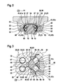
- Fig. 2 shows a cross section of the carriage 20 after Fig. 1 with the associated guide rail 10.
- the cutting plane is perpendicular to the longitudinal direction 11 in the middle of the main body 30th
- the guide rail 10 is made of steel and is surface hardened in the rail tracks 12. It extends with the illustrated constant cross-sectional shape straight along the longitudinal direction 11.
- On the guide rail 10 a total of four rail tracks 12 are arranged, which together with the opposite carriage tracks 41 define the support portion 23 of the endless circulation channel.
- the rail and carriage tracks 12; 41 are viewed in cross-section circular, wherein they are adapted with a close osculation of the spherical rolling elements 21. Further, it should be pointed to the WälzSystemhaltesteg 57, the rolling elements 21 together with the Guide portions 83 of the Wälz redesignhaltemaschine in the carriage 20 holds when it is not on the guide rail 10.
- the present guide carriage 20 has four rows of endlessly revolving rolling elements 21, which are loaded in a so-called O-arrangement.
- Fig. 3 shows an enlarged partial view of Fig. 2 in the region of a track insert 40. It can be seen, in particular, how the guide sections 83 of the rolling element guide part 80 engage behind the track insert 40.
- the track insert 40, the guide sections 83, the rolling element retaining web 57, the return channels 32, the rail tracks 12 and the rolling elements 21 are arranged mirror-symmetrically with respect to a plane of symmetry 68 which is parallel to the longitudinal direction 11.
- On each U-leg 35 of the main body 30 are each provided two planar bearing surfaces 60, which extend in a plane which is perpendicular to the plane of symmetry 68. Upwards or downwards, the bearing surfaces 60 are bounded by a shoulder 61, which is rounded in the corner, wherein it is otherwise formed in the manner of an insertion bevel.
- a guide portion 83 At the support surface 60 and the associated shoulder 61 is depending on a guide portion 83 at. It should be noted that the guide portion 83 with the in Fig. 3 illustrated constant cross-sectional shape over the entire length of the main body 30 extends.
- the guide portion 83 is provided with a nose which is bounded by a flat support surface 88 which is parallel to a side surface of the associated side surface 62; 63 of the V-shaped groove 33 in the main body 30 is arranged.
- the holding surface 88 engages behind the raceway insert 40, wherein the latter extends between the rolling elements 21 and bearing surface 60, so that it can rest on the holding surface 88.
- Adjacent to the holding surface 88 of the guide portion 83 is provided with a first WälzSystem Entrys Colour 86 which is circular in cross section viewed, wherein the corresponding radius is adapted to the rolling elements 21.
- a second WälzSystem Entrys response 58 is arranged, which is also viewed in cross-section also circular, wherein the corresponding radius is adapted to the rolling elements 21.
- an associated carriage track 41 is arranged, which is located on the raceway insert 40.
- the width 64 is smaller than the diameter of the spherical rolling elements 21. This prevents that the rolling elements 21 fall out of the guide carriage, if this is not on the guide rail 10. Otherwise, the rail track 12 is in the range of said gap.
- the guide section 83 On the side facing away from the raceway insert 40, the guide section 83 is provided with a free surface 87, which does not bear against the main body.
- the free surface 87 passes paragraph-free but with a slight bend in a longitudinal sealing lip 84, which is integrally provided on the guide portion 83.
- the tip of the longitudinal sealing lip 84 slidably abuts an associated side surface of the guide rail 10.
- the track insert is provided with a first planar bearing surface 42 against which the rolling element retaining web 57 rests.
- the first bearing surface 42 is oriented perpendicular to the plane of symmetry 68, wherein it is provided in the middle with a groove, in which the WälzSystemhaltesteg 57 engages so that it is aligned relative to the raceway liner exactly.
- a flat second bearing surface 43 is provided on the raceway insert 40, whose width 46 is greater than the width 45 of the first bearing surface 42 is formed.
- the width 45 of the first bearing surface 42 has been made small, so that the distance between the two rows of rolling elements is low.
- the width 46 of the second support surface 43 has been made large, so that it can serve as a support surface during grinding of the raceway insert 40.
- the second bearing surface 43 is also aligned perpendicular to the plane of symmetry 68, wherein in the middle of a groove 44 is arranged, with which it can be straightened during said grinding.
- the raceway insert 40 abuts against a V-shaped groove 33 in the main body directly, being pressed against the groove 33 only by the biasing force of the rolling elements 21.
- the V-shaped groove 33 has first and second side surfaces 62; 63, which enclose an angle of about 90 °.
- the supporting rolling elements 21 are completely within the extensions 66 of said side surfaces 62; 63 arranged.
- the V-shaped groove 33 is provided with a rounding 67, wherein the corresponding rounding diameter is made approximately equal to the width 46 of the second bearing surface 43.
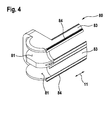
- Fig. 4 shows a partial perspective view of the WälzSystem ownsteils 80 in the region of the radially inner deflection surfaces 81.
- a WälzSystem ownsteil 80 are associated with two parallel rows of rolling elements. It therefore has at both ends two radially inner deflection surfaces 81 of the deflection channel, which extend in a circular arc with respect to a common axis of curvature having the same radius.
- two parallel guide portions 83 are integrally provided on the Wälz stressesteil 80, which extend in the longitudinal direction 11 with a constant cross-sectional shape.
- the guide portions 83 each have a longitudinal sealing lip 84 is provided, which bears sealingly against the guide rail when the carriage is mounted on this. Next hold the guide portions 83, the rolling elements in the carriage, if this is not on the guide rail.
- the Wälzköiper arrangementsteil 80 is mirror-symmetrical with respect to in Fig. 3 formed with the number 68 marked symmetry plane. In addition, it is mirror-symmetrical to a further plane of symmetry, which is perpendicular to the longitudinal direction 11.
- the rolling body guide member 80 is integrally formed. being composed of an elastomer, preferably of thermoplastic ether ester elastomer (TEEE, trade name "Hytrel").
Landscapes
- Engineering & Computer Science (AREA)
- General Engineering & Computer Science (AREA)
- Mechanical Engineering (AREA)
- Bearings For Parts Moving Linearly (AREA)
Applications Claiming Priority (1)
| Application Number | Priority Date | Filing Date | Title |
|---|---|---|---|
| DE102014210173.5A DE102014210173A1 (de) | 2014-05-28 | 2014-05-28 | Führungswagen mit Wälzkörper-Führungsabschnitt, der die Laufbahneinlage hintergreift |
Publications (3)
| Publication Number | Publication Date |
|---|---|
| EP2957782A2 true EP2957782A2 (fr) | 2015-12-23 |
| EP2957782A3 EP2957782A3 (fr) | 2016-02-24 |
| EP2957782B1 EP2957782B1 (fr) | 2017-12-13 |
Family
ID=53177187
Family Applications (1)
| Application Number | Title | Priority Date | Filing Date |
|---|---|---|---|
| EP15167455.3A Active EP2957782B1 (fr) | 2014-05-28 | 2015-05-13 | Chariot de guidage pour une section de guidage d'un corps roulant saisissant l'élément d'insertion de chemin de roulement |
Country Status (4)
| Country | Link |
|---|---|
| US (1) | US9476451B2 (fr) |
| EP (1) | EP2957782B1 (fr) |
| CN (1) | CN105275987B (fr) |
| DE (1) | DE102014210173A1 (fr) |
Families Citing this family (5)
| Publication number | Priority date | Publication date | Assignee | Title |
|---|---|---|---|---|
| DE102017210012B4 (de) * | 2016-07-07 | 2025-07-31 | Robert Bosch Gmbh | Linearbewegungsvorrichtung mit Schmierfilmüberwachung und isolierter Laufbahneinlage |
| DE202018003002U1 (de) * | 2018-06-27 | 2020-03-31 | Schneeberger Holding Ag | Linearbewegungsführung |
| DE102019200780A1 (de) * | 2019-01-23 | 2020-07-23 | Robert Bosch Gmbh | Führungswagen für eine Streckenführung, Streckenführung mit dem Führungswagen, und Verfahren zur Ermittlung einer Last des Führungswagens |
| DE102021002732A1 (de) * | 2021-05-26 | 2022-12-01 | Festo Se & Co. Kg | 1-8linearführungen aus wenigstens 2 unterschiedlichen werkstoffen |
| CN121630904A (zh) * | 2024-09-05 | 2026-03-10 | 精浚科技股份有限公司 | 线性滑轨及其防尘机构 |
Citations (2)
| Publication number | Priority date | Publication date | Assignee | Title |
|---|---|---|---|---|
| DE102006027061B4 (de) | 2006-06-10 | 2008-03-13 | Robert Bosch Gmbh | Führungsanordnung mit einem Führungswagen und einem an diesem mittels einer Adapterplatte angeordneten Messkopf |
| DE102007057834A1 (de) | 2007-11-30 | 2009-06-04 | Robert Bosch Gmbh | Linearbewegungsvorrichtung mit Beschichtung |
Family Cites Families (11)
| Publication number | Priority date | Publication date | Assignee | Title |
|---|---|---|---|---|
| US5195391A (en) * | 1988-10-31 | 1993-03-23 | Deutsche Star Gmbh | Linear guiding and driving unit |
| DE9011444U1 (de) * | 1989-09-04 | 1990-11-08 | Deutsche Star Gmbh, 8720 Schweinfurt | Wälzlager für Linearbewegungen |
| DE3931397A1 (de) * | 1989-09-20 | 1991-03-28 | Star Gmbh | Waelzlager fuer linearbewegungen stichwort: schienenfuehrung mit vorspannungseinstellung |
| US5431498A (en) * | 1994-04-11 | 1995-07-11 | Thomson Industries, Inc. | Linear motion bearing |
| DE102004059275A1 (de) * | 2004-12-09 | 2006-06-14 | Schaeffler Kg | Wälzlager für Linearbewegungen |
| DE102006060609A1 (de) * | 2006-12-21 | 2008-06-26 | AMK Arnold Müller GmbH & Co. KG | Lineares Wälzlagerelement |
| DE102007013516B4 (de) * | 2007-03-21 | 2013-04-04 | Robert Bosch Gmbh | Linearwälzlager |
| DE102008016356A1 (de) * | 2008-03-29 | 2009-10-01 | Schaeffler Kg | Umlaufführung für Wälzkörper und damit ausgerüstete Linear-Führungseinheit |
| DE102011083526A1 (de) * | 2011-05-11 | 2012-11-15 | Schaeffler Technologies AG & Co. KG | Führungskonzept für eine C-Bogen-förimige Schiene |
| TWI503489B (zh) * | 2012-05-23 | 2015-10-11 | Chieftech Prec Co Ltd | 線性滑軌之循環裝置及其半中間條 |
| DE202013003138U1 (de) * | 2013-04-03 | 2013-04-30 | Heinz Greiner | Linearführung für unbegrenzte Hubwege und Systeme |
-
2014
- 2014-05-28 DE DE102014210173.5A patent/DE102014210173A1/de not_active Withdrawn
-
2015
- 2015-05-13 EP EP15167455.3A patent/EP2957782B1/fr active Active
- 2015-05-28 CN CN201510281063.3A patent/CN105275987B/zh active Active
- 2015-05-28 US US14/723,818 patent/US9476451B2/en active Active
Patent Citations (2)
| Publication number | Priority date | Publication date | Assignee | Title |
|---|---|---|---|---|
| DE102006027061B4 (de) | 2006-06-10 | 2008-03-13 | Robert Bosch Gmbh | Führungsanordnung mit einem Führungswagen und einem an diesem mittels einer Adapterplatte angeordneten Messkopf |
| DE102007057834A1 (de) | 2007-11-30 | 2009-06-04 | Robert Bosch Gmbh | Linearbewegungsvorrichtung mit Beschichtung |
Also Published As
| Publication number | Publication date |
|---|---|
| DE102014210173A1 (de) | 2015-12-17 |
| EP2957782B1 (fr) | 2017-12-13 |
| CN105275987B (zh) | 2019-05-14 |
| EP2957782A3 (fr) | 2016-02-24 |
| US20150345553A1 (en) | 2015-12-03 |
| US9476451B2 (en) | 2016-10-25 |
| CN105275987A (zh) | 2016-01-27 |
Similar Documents
| Publication | Publication Date | Title |
|---|---|---|
| EP2952761B1 (fr) | Chariot de guidage doté d'alésage de fixation faisant partie d'un passage d'écoulement de lubrifiant | |
| EP2949954B1 (fr) | Chariot de guidage doté d'une partie de guidage d'élément roulant constituée d'un élastomère | |
| EP2957782B1 (fr) | Chariot de guidage pour une section de guidage d'un corps roulant saisissant l'élément d'insertion de chemin de roulement | |
| DE3324840A1 (de) | Waelzkoerperumlauflager | |
| EP3440368B1 (fr) | Chariot de guidage à capteur de déformation sur l'élément de chemin de roulement | |
| DE10016606B4 (de) | Vorrichtung zur Spieleinstellung in einer Linearführung | |
| EP1825156B1 (fr) | Palier a roulement pour deplacements lineaires | |
| DE19581261C1 (de) | Spieleinstellbares Linearlager | |
| DE202014004377U1 (de) | Führungswagen mit Abstreifblech mit tiefgezogenem Befestigungsdurchbruch | |
| DE102014219705A1 (de) | Lagerring | |
| DE9011413U1 (de) | Linearantrieb | |
| EP1953401B1 (fr) | Wagon de tête pour guides de rails profilés | |
| DE102015213782A1 (de) | Geschweißter Hauptkörper eines Linearwälzlagers | |
| WO2004001245A1 (fr) | Palier a roulement lineaire a tube de retour | |
| DE102016210751A1 (de) | Linearführung | |
| EP1110006B1 (fr) | Palier a roulement lineaire | |
| EP3565982B1 (fr) | Cage à corps de roulement pour un rail télescopique ou un guide linéaire | |
| DE202015102452U1 (de) | Führungswagen mit Schmierrinne und Kunststofffolie | |
| EP0418875B1 (fr) | Guidage linéaire avec des évidements pour l'assemblage | |
| EP2397712A1 (fr) | Guidage linéaire avec une cage à guidage forcé | |
| DE10036016A1 (de) | Linearwälzlager | |
| DE19708370A1 (de) | Kugellager für Längsbewegungen zwischen einer Welle und einem Gehäuse | |
| DE102015200294A1 (de) | Ringverschraubung | |
| DE20200575U1 (de) | Abdeckung zum Verschließen von mindestens zwei Bohrungen | |
| DE20214377U1 (de) | Teleskopsäule (II) |
Legal Events
| Date | Code | Title | Description |
|---|---|---|---|
| PUAI | Public reference made under article 153(3) epc to a published international application that has entered the european phase |
Free format text: ORIGINAL CODE: 0009012 |
|
| AK | Designated contracting states |
Kind code of ref document: A2 Designated state(s): AL AT BE BG CH CY CZ DE DK EE ES FI FR GB GR HR HU IE IS IT LI LT LU LV MC MK MT NL NO PL PT RO RS SE SI SK SM TR |
|
| AX | Request for extension of the european patent |
Extension state: BA ME |
|
| PUAL | Search report despatched |
Free format text: ORIGINAL CODE: 0009013 |
|
| AK | Designated contracting states |
Kind code of ref document: A3 Designated state(s): AL AT BE BG CH CY CZ DE DK EE ES FI FR GB GR HR HU IE IS IT LI LT LU LV MC MK MT NL NO PL PT RO RS SE SI SK SM TR |
|
| AX | Request for extension of the european patent |
Extension state: BA ME |
|
| RIC1 | Information provided on ipc code assigned before grant |
Ipc: F16C 29/06 20060101AFI20160115BHEP |
|
| 17P | Request for examination filed |
Effective date: 20160824 |
|
| RBV | Designated contracting states (corrected) |
Designated state(s): AL AT BE BG CH CY CZ DE DK EE ES FI FR GB GR HR HU IE IS IT LI LT LU LV MC MK MT NL NO PL PT RO RS SE SI SK SM TR |
|
| RIC1 | Information provided on ipc code assigned before grant |
Ipc: F16C 29/08 20060101ALN20170620BHEP Ipc: F16C 29/06 20060101AFI20170620BHEP Ipc: F16C 33/60 20060101ALN20170620BHEP Ipc: F16C 43/04 20060101ALN20170620BHEP |
|
| GRAP | Despatch of communication of intention to grant a patent |
Free format text: ORIGINAL CODE: EPIDOSNIGR1 |
|
| INTG | Intention to grant announced |
Effective date: 20170818 |
|
| GRAS | Grant fee paid |
Free format text: ORIGINAL CODE: EPIDOSNIGR3 |
|
| GRAA | (expected) grant |
Free format text: ORIGINAL CODE: 0009210 |
|
| REG | Reference to a national code |
Ref country code: GB Ref legal event code: FG4D Free format text: NOT ENGLISH |
|
| REG | Reference to a national code |
Ref country code: AT Ref legal event code: REF Ref document number: 954693 Country of ref document: AT Kind code of ref document: T Effective date: 20171215 Ref country code: CH Ref legal event code: EP |
|
| REG | Reference to a national code |
Ref country code: IE Ref legal event code: FG4D Free format text: LANGUAGE OF EP DOCUMENT: GERMAN |
|
| REG | Reference to a national code |
Ref country code: DE Ref legal event code: R096 Ref document number: 502015002538 Country of ref document: DE |
|
| REG | Reference to a national code |
Ref country code: RO Ref legal event code: EPE |
|
| REG | Reference to a national code |
Ref country code: NL Ref legal event code: MP Effective date: 20171213 |
|
| PG25 | Lapsed in a contracting state [announced via postgrant information from national office to epo] |
Ref country code: FI Free format text: LAPSE BECAUSE OF FAILURE TO SUBMIT A TRANSLATION OF THE DESCRIPTION OR TO PAY THE FEE WITHIN THE PRESCRIBED TIME-LIMIT Effective date: 20171213 Ref country code: NO Free format text: LAPSE BECAUSE OF FAILURE TO SUBMIT A TRANSLATION OF THE DESCRIPTION OR TO PAY THE FEE WITHIN THE PRESCRIBED TIME-LIMIT Effective date: 20180313 Ref country code: SE Free format text: LAPSE BECAUSE OF FAILURE TO SUBMIT A TRANSLATION OF THE DESCRIPTION OR TO PAY THE FEE WITHIN THE PRESCRIBED TIME-LIMIT Effective date: 20171213 |
|
| PG25 | Lapsed in a contracting state [announced via postgrant information from national office to epo] |
Ref country code: HR Free format text: LAPSE BECAUSE OF FAILURE TO SUBMIT A TRANSLATION OF THE DESCRIPTION OR TO PAY THE FEE WITHIN THE PRESCRIBED TIME-LIMIT Effective date: 20171213 Ref country code: BG Free format text: LAPSE BECAUSE OF FAILURE TO SUBMIT A TRANSLATION OF THE DESCRIPTION OR TO PAY THE FEE WITHIN THE PRESCRIBED TIME-LIMIT Effective date: 20180313 Ref country code: GR Free format text: LAPSE BECAUSE OF FAILURE TO SUBMIT A TRANSLATION OF THE DESCRIPTION OR TO PAY THE FEE WITHIN THE PRESCRIBED TIME-LIMIT Effective date: 20180314 Ref country code: RS Free format text: LAPSE BECAUSE OF FAILURE TO SUBMIT A TRANSLATION OF THE DESCRIPTION OR TO PAY THE FEE WITHIN THE PRESCRIBED TIME-LIMIT Effective date: 20171213 Ref country code: LV Free format text: LAPSE BECAUSE OF FAILURE TO SUBMIT A TRANSLATION OF THE DESCRIPTION OR TO PAY THE FEE WITHIN THE PRESCRIBED TIME-LIMIT Effective date: 20171213 |
|
| PG25 | Lapsed in a contracting state [announced via postgrant information from national office to epo] |
Ref country code: NL Free format text: LAPSE BECAUSE OF FAILURE TO SUBMIT A TRANSLATION OF THE DESCRIPTION OR TO PAY THE FEE WITHIN THE PRESCRIBED TIME-LIMIT Effective date: 20171213 |
|
| PG25 | Lapsed in a contracting state [announced via postgrant information from national office to epo] |
Ref country code: ES Free format text: LAPSE BECAUSE OF FAILURE TO SUBMIT A TRANSLATION OF THE DESCRIPTION OR TO PAY THE FEE WITHIN THE PRESCRIBED TIME-LIMIT Effective date: 20171213 Ref country code: CZ Free format text: LAPSE BECAUSE OF FAILURE TO SUBMIT A TRANSLATION OF THE DESCRIPTION OR TO PAY THE FEE WITHIN THE PRESCRIBED TIME-LIMIT Effective date: 20171213 Ref country code: SK Free format text: LAPSE BECAUSE OF FAILURE TO SUBMIT A TRANSLATION OF THE DESCRIPTION OR TO PAY THE FEE WITHIN THE PRESCRIBED TIME-LIMIT Effective date: 20171213 Ref country code: CY Free format text: LAPSE BECAUSE OF FAILURE TO SUBMIT A TRANSLATION OF THE DESCRIPTION OR TO PAY THE FEE WITHIN THE PRESCRIBED TIME-LIMIT Effective date: 20171213 Ref country code: EE Free format text: LAPSE BECAUSE OF FAILURE TO SUBMIT A TRANSLATION OF THE DESCRIPTION OR TO PAY THE FEE WITHIN THE PRESCRIBED TIME-LIMIT Effective date: 20171213 |
|
| PG25 | Lapsed in a contracting state [announced via postgrant information from national office to epo] |
Ref country code: PL Free format text: LAPSE BECAUSE OF FAILURE TO SUBMIT A TRANSLATION OF THE DESCRIPTION OR TO PAY THE FEE WITHIN THE PRESCRIBED TIME-LIMIT Effective date: 20171213 Ref country code: IS Free format text: LAPSE BECAUSE OF FAILURE TO SUBMIT A TRANSLATION OF THE DESCRIPTION OR TO PAY THE FEE WITHIN THE PRESCRIBED TIME-LIMIT Effective date: 20180413 Ref country code: SM Free format text: LAPSE BECAUSE OF FAILURE TO SUBMIT A TRANSLATION OF THE DESCRIPTION OR TO PAY THE FEE WITHIN THE PRESCRIBED TIME-LIMIT Effective date: 20171213 |
|
| REG | Reference to a national code |
Ref country code: DE Ref legal event code: R097 Ref document number: 502015002538 Country of ref document: DE |
|
| PG25 | Lapsed in a contracting state [announced via postgrant information from national office to epo] |
Ref country code: MT Free format text: LAPSE BECAUSE OF FAILURE TO SUBMIT A TRANSLATION OF THE DESCRIPTION OR TO PAY THE FEE WITHIN THE PRESCRIBED TIME-LIMIT Effective date: 20171213 |
|
| PLBE | No opposition filed within time limit |
Free format text: ORIGINAL CODE: 0009261 |
|
| STAA | Information on the status of an ep patent application or granted ep patent |
Free format text: STATUS: NO OPPOSITION FILED WITHIN TIME LIMIT |
|
| 26N | No opposition filed |
Effective date: 20180914 |
|
| PG25 | Lapsed in a contracting state [announced via postgrant information from national office to epo] |
Ref country code: DK Free format text: LAPSE BECAUSE OF FAILURE TO SUBMIT A TRANSLATION OF THE DESCRIPTION OR TO PAY THE FEE WITHIN THE PRESCRIBED TIME-LIMIT Effective date: 20171213 |
|
| REG | Reference to a national code |
Ref country code: CH Ref legal event code: PL |
|
| REG | Reference to a national code |
Ref country code: BE Ref legal event code: MM Effective date: 20180531 |
|
| PG25 | Lapsed in a contracting state [announced via postgrant information from national office to epo] |
Ref country code: MC Free format text: LAPSE BECAUSE OF FAILURE TO SUBMIT A TRANSLATION OF THE DESCRIPTION OR TO PAY THE FEE WITHIN THE PRESCRIBED TIME-LIMIT Effective date: 20171213 |
|
| REG | Reference to a national code |
Ref country code: IE Ref legal event code: MM4A |
|
| PG25 | Lapsed in a contracting state [announced via postgrant information from national office to epo] |
Ref country code: LI Free format text: LAPSE BECAUSE OF NON-PAYMENT OF DUE FEES Effective date: 20180531 Ref country code: CH Free format text: LAPSE BECAUSE OF NON-PAYMENT OF DUE FEES Effective date: 20180531 Ref country code: SI Free format text: LAPSE BECAUSE OF FAILURE TO SUBMIT A TRANSLATION OF THE DESCRIPTION OR TO PAY THE FEE WITHIN THE PRESCRIBED TIME-LIMIT Effective date: 20171213 |
|
| PG25 | Lapsed in a contracting state [announced via postgrant information from national office to epo] |
Ref country code: LU Free format text: LAPSE BECAUSE OF NON-PAYMENT OF DUE FEES Effective date: 20180513 |
|
| PG25 | Lapsed in a contracting state [announced via postgrant information from national office to epo] |
Ref country code: IE Free format text: LAPSE BECAUSE OF NON-PAYMENT OF DUE FEES Effective date: 20180513 Ref country code: FR Free format text: LAPSE BECAUSE OF NON-PAYMENT OF DUE FEES Effective date: 20180531 |
|
| PG25 | Lapsed in a contracting state [announced via postgrant information from national office to epo] |
Ref country code: BE Free format text: LAPSE BECAUSE OF NON-PAYMENT OF DUE FEES Effective date: 20180531 |
|
| GBPC | Gb: european patent ceased through non-payment of renewal fee |
Effective date: 20190513 |
|
| PG25 | Lapsed in a contracting state [announced via postgrant information from national office to epo] |
Ref country code: TR Free format text: LAPSE BECAUSE OF FAILURE TO SUBMIT A TRANSLATION OF THE DESCRIPTION OR TO PAY THE FEE WITHIN THE PRESCRIBED TIME-LIMIT Effective date: 20171213 |
|
| PG25 | Lapsed in a contracting state [announced via postgrant information from national office to epo] |
Ref country code: GB Free format text: LAPSE BECAUSE OF NON-PAYMENT OF DUE FEES Effective date: 20190513 |
|
| PG25 | Lapsed in a contracting state [announced via postgrant information from national office to epo] |
Ref country code: PT Free format text: LAPSE BECAUSE OF FAILURE TO SUBMIT A TRANSLATION OF THE DESCRIPTION OR TO PAY THE FEE WITHIN THE PRESCRIBED TIME-LIMIT Effective date: 20171213 |
|
| PG25 | Lapsed in a contracting state [announced via postgrant information from national office to epo] |
Ref country code: HU Free format text: LAPSE BECAUSE OF FAILURE TO SUBMIT A TRANSLATION OF THE DESCRIPTION OR TO PAY THE FEE WITHIN THE PRESCRIBED TIME-LIMIT; INVALID AB INITIO Effective date: 20150513 Ref country code: MK Free format text: LAPSE BECAUSE OF NON-PAYMENT OF DUE FEES Effective date: 20171213 Ref country code: LT Free format text: LAPSE BECAUSE OF FAILURE TO SUBMIT A TRANSLATION OF THE DESCRIPTION OR TO PAY THE FEE WITHIN THE PRESCRIBED TIME-LIMIT Effective date: 20171213 |
|
| PG25 | Lapsed in a contracting state [announced via postgrant information from national office to epo] |
Ref country code: AL Free format text: LAPSE BECAUSE OF FAILURE TO SUBMIT A TRANSLATION OF THE DESCRIPTION OR TO PAY THE FEE WITHIN THE PRESCRIBED TIME-LIMIT Effective date: 20171213 |
|
| REG | Reference to a national code |
Ref country code: AT Ref legal event code: MM01 Ref document number: 954693 Country of ref document: AT Kind code of ref document: T Effective date: 20200513 |
|
| PG25 | Lapsed in a contracting state [announced via postgrant information from national office to epo] |
Ref country code: AT Free format text: LAPSE BECAUSE OF NON-PAYMENT OF DUE FEES Effective date: 20200513 |
|
| PGFP | Annual fee paid to national office [announced via postgrant information from national office to epo] |
Ref country code: IT Payment date: 20250530 Year of fee payment: 11 |
|
| PGFP | Annual fee paid to national office [announced via postgrant information from national office to epo] |
Ref country code: RO Payment date: 20250430 Year of fee payment: 11 |
|
| PGFP | Annual fee paid to national office [announced via postgrant information from national office to epo] |
Ref country code: DE Payment date: 20250716 Year of fee payment: 11 |