EP2957787B1 - Kupplung mit strukturierter scheibe - Google Patents
Kupplung mit strukturierter scheibe Download PDFInfo
- Publication number
- EP2957787B1 EP2957787B1 EP15171873.1A EP15171873A EP2957787B1 EP 2957787 B1 EP2957787 B1 EP 2957787B1 EP 15171873 A EP15171873 A EP 15171873A EP 2957787 B1 EP2957787 B1 EP 2957787B1
- Authority
- EP
- European Patent Office
- Prior art keywords
- contoured
- disc coupling
- thickness
- webs
- coupling
- Prior art date
- Legal status (The legal status is an assumption and is not a legal conclusion. Google has not performed a legal analysis and makes no representation as to the accuracy of the status listed.)
- Active
Links
Images

Classifications
-
- F—MECHANICAL ENGINEERING; LIGHTING; HEATING; WEAPONS; BLASTING
- F16—ENGINEERING ELEMENTS AND UNITS; GENERAL MEASURES FOR PRODUCING AND MAINTAINING EFFECTIVE FUNCTIONING OF MACHINES OR INSTALLATIONS; THERMAL INSULATION IN GENERAL
- F16D—COUPLINGS FOR TRANSMITTING ROTATION; CLUTCHES; BRAKES
- F16D3/00—Yielding couplings, i.e. with means permitting movement between the connected parts during the drive
- F16D3/50—Yielding couplings, i.e. with means permitting movement between the connected parts during the drive with the coupling parts connected by one or more intermediate members
- F16D3/78—Yielding couplings, i.e. with means permitting movement between the connected parts during the drive with the coupling parts connected by one or more intermediate members shaped as an elastic disc or flat ring, arranged perpendicular to the axis of the coupling parts, different sets of spots of the disc or ring being attached to each coupling part, e.g. Hardy couplings
- F16D3/79—Yielding couplings, i.e. with means permitting movement between the connected parts during the drive with the coupling parts connected by one or more intermediate members shaped as an elastic disc or flat ring, arranged perpendicular to the axis of the coupling parts, different sets of spots of the disc or ring being attached to each coupling part, e.g. Hardy couplings the disc or ring being metallic
-
- F—MECHANICAL ENGINEERING; LIGHTING; HEATING; WEAPONS; BLASTING
- F16—ENGINEERING ELEMENTS AND UNITS; GENERAL MEASURES FOR PRODUCING AND MAINTAINING EFFECTIVE FUNCTIONING OF MACHINES OR INSTALLATIONS; THERMAL INSULATION IN GENERAL
- F16D—COUPLINGS FOR TRANSMITTING ROTATION; CLUTCHES; BRAKES
- F16D3/00—Yielding couplings, i.e. with means permitting movement between the connected parts during the drive
- F16D3/50—Yielding couplings, i.e. with means permitting movement between the connected parts during the drive with the coupling parts connected by one or more intermediate members
- F16D3/60—Yielding couplings, i.e. with means permitting movement between the connected parts during the drive with the coupling parts connected by one or more intermediate members comprising pushing or pulling links attached to both parts
- F16D3/62—Yielding couplings, i.e. with means permitting movement between the connected parts during the drive with the coupling parts connected by one or more intermediate members comprising pushing or pulling links attached to both parts the links or their attachments being elastic
Definitions
- the present invention relates to high performance flexible couplings, and in particular, to a contoured disc coupling.
- Flexible couplings are used in machinery to connect a first rotating part to a second rotating part. Flexible couplings are designed to transmit torque between the rotating parts, accommodate misalignment between the rotating parts, and to compensate for end movement of either of the rotating parts. A lot of stress can be produced in the system due to the amount of torque that is being transmitted and the amount of misalignment or end movement of the rotating parts. Flexible couplings are used to transmit the torque and absorb stress. Flexible couplings can include gear couplings or metallic couplings. Gear couplings have a first and second set of gear teeth that mesh and move together to transmit torque. Metallic couplings include diaphragm couplings and disc couplings that transmit torque through the flexure of metallic material.
- Diaphragm couplings and disc couplings differ in how they transmit torque and accommodate flexure of the metallic material.
- Diaphragm couplings are plates (or diaphragms) that can be used as a single piece or multiple pieces. Diaphragm couplings can be contoured, convoluted, or have cut-out portions. Diaphragm couplings accommodate flexure in the metal in the radial direction, either from the outer diameter to the inner diameter or vice versa. The torque is thus transferred as shear stress through the diaphragm coupling and axial and angular deflection are accommodated by bending.
- Disc couplings are stacks of thin flat sheets of metal that are bolted together in a stack.
- Disc couplings accommodate flexure in the metal between bolts. Adjacent bolts are alternately fastened to the two rotating parts so that one bolt can act as the load transmitter and the adjacent bolt can act as the load receiver. The torque is thus transferred as tensile stress through the disc coupling and axial and angular deflection are accommodated by bending.
- GB 2342424A describes a flexible annular coupling with a predetermined buckling direction.
- US 5286231A1 describes a flexible elastomer coupling element.
- US 5163876A describes a method of constructing a compositing flexible coupling element.
- a contoured disc coupling disclosed herein includes a plurality of fastening locations. Each fastening location has a body portion and an aperture running through the body portion. A plurality of webs extend between adjacent fastening locations, and each web has a contoured shape.
- the contoured disc coupling may be used in a power transmission system.
- a power transmission system disclosed herein includes a first shaft, a second shaft, and a disc coupling attaching the first shaft to the second shaft.
- the disc coupling includes a central opening, a plurality of fastening locations positioned around the central opening, and a plurality of webs that each have a contoured shape extending between the plurality of fastening locations around the central opening.
- the present disclosure includes a contoured disc coupling that can be positioned between two rotating parts to transfer torque between the two rotating parts.
- the contoured disc coupling includes a plurality of fastening locations with apertures through which a fastener can be placed.
- a plurality of webs extend between the plurality of fastening locations.
- Each of the webs has a contoured shape with a first thickness on a first end and a second end, and a second thickness in the center of the web. The first thickness is thicker than the second thickness, and the web tapers between the two thicknesses to create the contoured shape.
- the contoured shape of the webs allows each of the webs to efficiently and effectively transfer torque between adjacent fastening locations.
- the contoured shape of the webs also allows each of the webs to bend and flex to accommodate axial and angular deflections between the two rotating parts.
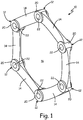
- FIG. 1 is perspective view of contoured disc coupling 10.
- Contoured disc coupling 10 includes fastening locations 12, webs 14, and central opening 16. Each fastening location 12 includes body portion 20 and aperture 22.
- Contoured disc coupling 10 includes fastening locations 12 and webs 14 that are positioned around central opening 16.
- Contoured disc coupling 10 is a single piece. Webs 14 extend between adjacent fastening locations 12 to connect fastening locations 12 together.
- Each fastening location 12 includes body portion 20 and aperture 22.
- Body portions 20 are cylindrically shaped.
- One aperture 22 extends from a first side to a second side of each body portion 20. Apertures 22 are capable of receiving a fastener when contoured disc coupling 10 is installed between two rotating parts.
- Webs 14 are contoured with a first thickness at a first end and a second end of each web 14, and a second thickness at a center of each web.
- the first thickness is thicker than the second thickness in the embodiment shown.
- the slope of webs 14 tapers between the first end and the center and between the second end and the center.
- Webs 14 are contoured to accommodate tensile and bending stresses.
- Contoured disc coupling 10 has to withstand high tensile stresses due to the torque that will be transmitted through contoured disc coupling 10.
- Contoured disc coupling 10 also has to withstand high bending stresses that are associated with axial and angular deflection between the two rotating parts between which contoured disc coupling 10 is positioned.
- contoured shaped of webs 14 allows them to withstand the tensile and bending stresses stemming from the torque, speed, and axial and angular deflections of the two rotating parts.
- Prior art disc couplings include stacks of thin flat discs that are bolted together in a pack. These disc couplings have a potential failure mode in which the discs rub against each other, generating heat and fretting. This can ultimately lead to the formation of cracks.
- Contoured disc coupling 10 eliminates this potential failure mode, as contoured disc coupling 10 is a single piece and does not have multiple parts that can rub against each other to generate heat and fretting.
- Contoured disc coupling 10 also has increased deflection capability compared to prior art disc couplings. This allows contoured disc coupling 10 to be used in more applications than prior art disc couplings. Further, the stresses in contoured disc coupling 10 can be more accurately predicted, make contoured disc coupling 10 more reliable than prior art disc couplings. Being able to accurately predict the stresses in contoured disc coupling 10 also allows contoured disc coupling 10 to be designed and tailored for specific uses. This allows flexibility in the design to ensure that high fatigue stresses are not located near the edges of contoured disc coupling 10.
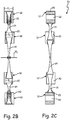
- FIG. 2A is a front plan view of contoured disc coupling 10.
- FIG. 2B is a side elevation view of contoured disc coupling 10.
- FIG. 2C is a cross-sectional side view of contoured disc coupling 10 taken along line C-C in FIG. 2A .
- Contoured disc coupling 10 includes fastening locations 12, webs 14, and central opening 16. Each fastening location 12 includes body portion 20 and aperture 22.
- Contoured disc coupling 10 includes fastening locations 12 and webs 14 positioned around central opening 16.
- Contoured disc coupling 10 is a single piece that can be manufactured using a variety of processes.
- contoured disc coupling 10 is an additively manufactured monolithic part.
- contoured disc coupling 10 is manufactured with a multiaxis machining manufacturing process.
- Contoured disc coupling 10 is made out of a metallic material in the embodiment shown, but can be made out of other suitable materials in alternate embodiments.
- Webs 14 extend between adjacent fastening locations 12 and are attached on either end to fastening locations 12.
- Fastening locations 12 each include body portion 20 and aperture 22.
- Body portions 20 are cylindrically shaped and apertures 22 run from a first side to a second side of each body portion 20.
- Apertures 22 are capable of receiving a fastener when contoured disc coupling 10 is installed between two rotating parts.
- Webs 14 each have a contoured shape with first thickness T 1 at a first end and a second end of each web 14, and second thickness T 2 in the center of each web 14.
- First thickness T 1 is larger than second thickness T 2 in the embodiment shown. This difference in thickness gives webs 14 their contoured shape, as each web 14 tapers from first thickness T 1 to second thickness T 2 .
- Fastening locations 12 have third thickness T 3 that is larger than first thickness T 1 .
- Third thickness T 3 is larger than first thickness T 1 so that webs 14 can attach to fastening locations 12 and be positioned a distance away from the front and back surface of fastening locations 12.
- Contoured disc coupling 10 is designed to transmit torque in tension between fastening locations 12.
- One fastening location 12 acts as a load distributor and an adjacent fastening location 12 acts as a load receiver.
- webs 14 In order for torque to be efficiently transmitted between adjacent fastening locations 12, webs 14 have to be capable of withstanding high tensile and bending stresses. The tensile stresses come from the transfer of torque across webs 14 and the bending stresses come from the axial and angular deflections of the rotating parts between which contoured disc coupling 10 is positioned. Contoured disc coupling 10 is designed to evenly distribute the tensile and bending stresses across webs 14.
- First thickness T 1 and second thickness T 2 of webs 14 are selected to evenly distribute the tensile and bending stresses in contoured disc coupling 10. In the center of webs 14 the only significant stresses are tensile stresses from torque and some bending stress from angular velocity. Second thickness T 2 of the center of web 14 is thus selected based solely on the torque required for any given application. Second thickness T 2 tapers to first thickness T 1 in both directions. The taper is designed to distribute bending stresses along a face of each of webs 14. Thus, first thickness T 1 at the first end and second end of each web 14 is selected in light of the taper required to accommodate the bending stresses that will be present in any given application. Third thickness T 3 is selected so that webs 14 can be attached to fastening locations 12 a distance away from the front or back face of fastening locations 12. This prevents fatigue and fretting on the first end and the second end of webs 14.
- Prior art disc couplings consisted of thin flat discs that were stacked together. Some of the problems present with prior art disc couplings include the following. First, deflection of the discs was limited depending on where the disc was positioned in the stack. Second, stress due to bending was concentrated around the fastening locations, causing fretting in these areas. Third, the discs in the stack rubbed together and generated heat, leading to fractures in the discs.
- Contoured disc coupling 10 eliminates the problems present in prior art disc couplings.
- contoured webs 14 allow contoured disc coupling 10 to deflect more than was previously possible, as the contoured shape more easily accommodates bending stresses.
- contoured disc coupling 10 is a single piece, allowing webs 14 to more easily deflect.
- the contoured shape of webs 14 is designed to transfer bending stresses away from fastening locations 12 and out into webs 14. This prevents fretting around fastening locations 12.
- contoured disc coupling 10 is a single piece so there are no moving parts that can rub together to generate heat and potentially cause fracturing.
- contoured disc coupling 10 Another advantage of contoured disc coupling 10 is that the contoured design can be tailored so that the highest fatigue stresses in contoured disc coupling 10 are not located near an edge.
- Prior art disc couplings faced this problem, as the surface finish and exact contour of the disc edge were difficult to control during manufacturing. The imprecision in the surface finish and disc edge contour caused prior art disc couplings to experience fatigue near surfaces of the disc coupling.
- Contoured disc coupling 10 has eliminated this problem, as the contoured shape of webs 14 is designed such that the highest fatigue stresses occur in flat, wide areas of contoured disc coupling 10 where the surface finish can be tightly controlled and inspection is much easier.
- contoured disc coupling 10 A further advantage of contoured disc coupling 10 is that the stresses in contoured disc coupling 10 can be accurately predicted. More accurately predicting the stresses in contoured disc coupling 10 allows for the design of contoured disc coupling 10 to be optimized. Further, being able to more accurately predict the stresses in contoured disc coupling 10 allows for greater reliability in using contoured disc coupling 10 in different settings. This expands the applications in which contoured disc coupling 10 can be used compared to prior art disc couplings. The applications of prior art disc couplings were limited because the design either could not meet operational needs or because the reliability of the disc coupling could not be accurately established. Contoured disc coupling 10 eliminates these concerns and contoured disc coupling 10 can be used in broader applications than was previously possible.
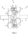
- FIG. 3 is a side elevation view of contoured disc coupling 10 positioned between first rotating part 30 and second rotating part 40.
- Disc coupling 10 includes fastening locations 12 and webs 14.
- First rotating part 30 includes fastening plate 32 and shaft 34.
- Second rotating part 40 includes fastening plate 42 and shaft 44. Also shown are fasteners 50, nuts 52, spacers 54, and washers 56.
- Disc coupling 10 is positioned between first rotating part 30 and second rotating part 40.
- Disc coupling 10 includes fastening locations 12 and webs 14 that extend between adjacent fastening locations 12.
- Webs 14 have a contoured shape with first thickness T 1 at a first end and a second end of web 14, and a second thickness T 2 in the center of web 14.
- Each fastening location 12 includes an aperture through which a fastener can pass.
- First rotating part 30 includes fastening plate 32 and shaft 34.
- Fastening plate 32 includes a plurality of apertures through which a fastener can pass.
- Second rotating part 40 includes a fastening plate 42 and shaft 44.
- Fastening plate 42 includes a plurality of apertures through which a fastener can pass.
- Fastening plate 32 and fastening plate 42 are tri-lobed plates in the embodiment shown in FIG. 3 , but can by any suitable plate, including scalloped or triangular plates, in alternate embodiments.
- Each aperture in fastening locations 12 is aligned with an aperture in either fastening plate 32 or fastening plate 42. This allows a fastener to pass through an aperture in one of fastening plate 32 or fastening plate 42 and then through fastening location 12.
- Fasteners 50 are used to connect first rotating part 30 to second rotating part 40 with contoured disc coupling 10 positioned in between. Fasteners 50 are alternately fastened to first rotating part 30 and second rotating part 40 so that one fastening location 12 can act as a load transmitter and an adjacent fastening location 12 can act as a load receiver. Fasteners 50 are placed through the apertures in fastenings locations 12 and through an aperture in either fastening plate 32 or fastening plate 42. Spacers 54 are provided to space contoured disc coupling 10 away from fastening plate 32 and fastening plate 42. Washers 56 are positioned between nuts 52 and contoured disc coupling 10. In alternate embodiments, spacers 54 and washers 56 can be eliminated.
- Contoured disc coupling 10 is advantageous over prior art disc couplings. Contoured disc coupling 10 transmits torque more efficiently and effectively than prior art disc couplings and can deflect more to accommodate the stresses put on it. The stresses that will be present in contoured disc coupling 10 in any given setting can also be more accurately projected. This allows contoured disc coupling 10 to be designed with more precision depending on what application it will be used in. This allows contoured disc coupling 10 to be used in more settings than was previously possible.
Landscapes
- Engineering & Computer Science (AREA)
- General Engineering & Computer Science (AREA)
- Mechanical Engineering (AREA)
- Connection Of Plates (AREA)
- Replacement Of Web Rolls (AREA)
- Tents Or Canopies (AREA)
- Polishing Bodies And Polishing Tools (AREA)
Claims (10)
- Kupplung (10) mit strukturierter Scheibe, umfassend:eine Vielzahl von Befestigungsstellen (12), wobei jede Befestigungsstelle (12) einen Körperabschnitt (20) mit einer ersten Fläche und einer zweiten Fläche gegenüber der ersten Fläche und einen Durchlass (22), der durch den Körperabschnitt (20) von der ersten Fläche zur zweiten Fläche verläuft, aufweist; undeine Vielzahl von Stegen (14), die sich zwischen angrenzenden Befestigungsstellen (12) erstreckt, wobei die Vielzahl von Befestigungsstellen (12) und die Vielzahl von Stegen (14) um eine zentrale Öffnung (16) positioniert sind,wobei jeder Steg (14) eine strukturierte Form aufweist und jeder Steg (14) eine erste Dicke (T1) an einem ersten Ende des Stegs (14) und an einem zweiten Ende des Stegs (14) und eine zweite Dicke (T2) in der Mitte des Stegs (14) aufweist, wobei der Körperabschnitt (20) der Befestigungsstelle eine dritte Dicke (T3) von der ersten Fläche zur zweiten Fläche aufweist, die größer als die erste Dicke (T1) des ersten Endes des Stegs (14) und des zweiten Endes des Stegs (14) ist, wobei das erste des Stegs (14) und das zweite Ende des Stegs (14) in einem Abstand weg von der ersten Fläche und der zweiten Fläche der Befestigungsstellen (12) positioniert sind; dadurch gekennzeichnet, dass die Kupplung mit strukturierter Scheibe einstückig ist und die Vielzahl von Befestigungsstellen und die Vielzahl von Stegen aus einem Metallwerkstoff bestehen.
- Kupplung (10) mit strukturierter Scheibe nach Anspruch 1, wobei die erste Dicke (T1) größer als die zweite Dicke (T2) ist.
- Kupplung (10) mit strukturierter Scheibe nach Anspruch 2, wobei sich jeder der Vielzahl von Stegen (14) zwischen der ersten Dicke (T1) und der zweiten Dicke (T2) verjüngt, wobei die Verjüngung Biegebeanspruchungen entlang einer Fläche jedes der Stege (14) verteilt.
- Kupplung (10) mit strukturierter Scheibe nach Anspruch 1, 2 oder 3, wobei die Befestigungsstelle (12) eine dritte Dicke (T3) aufweist, wobei die dritte Dicke (T3) größer als die erste Dicke (T1) ist.
- Kupplung (10) mit strukturierter Scheibe nach einem vorhergehenden Anspruch, wobei die Vielzahl von Befestigungsstellen (12) um einen Rand der Scheibenkupplung (10) angeordnet ist.
- Kupplung (10) mit strukturierter Scheibe nach einem vorhergehenden Anspruch, wobei die Scheibenkupplung (10) additiv gefertigt ist.
- Kraftübertragungssystem, umfassend:eine erste Welle (34);eine zweite Welle (44); undeine Scheibenkupplung (10) nach Anspruch 1, welche die erste Welle (34) mit der zweiten Welle (44) verbindet.
- Kraftübertragungssystem nach Anspruch 7, wobei die erste Dicke (T1) größer als die zweite Dicke (T2) ist.
- Kraftübertragungssystem nach Anspruch 7 oder 8, wobei sich jeder der Vielzahl von Stegen (14) zwischen der ersten Dicke (T1) und der zweiten Dicke (T2) verjüngt, wobei die Verjüngung Biegebeanspruchungen entlang einer Fläche jedes der Stege (14) verteilt.
- Kraftübertragungssystem nach einem der Ansprüche 7 bis 9, wobei die Scheibenkupplung (10) additiv gefertigt ist.
Applications Claiming Priority (1)
| Application Number | Priority Date | Filing Date | Title |
|---|---|---|---|
| US14/305,672 US9458891B2 (en) | 2014-06-16 | 2014-06-16 | Contoured disc coupling |
Publications (3)
| Publication Number | Publication Date |
|---|---|
| EP2957787A2 EP2957787A2 (de) | 2015-12-23 |
| EP2957787A3 EP2957787A3 (de) | 2016-06-29 |
| EP2957787B1 true EP2957787B1 (de) | 2020-12-02 |
Family
ID=53396364
Family Applications (1)
| Application Number | Title | Priority Date | Filing Date |
|---|---|---|---|
| EP15171873.1A Active EP2957787B1 (de) | 2014-06-16 | 2015-06-12 | Kupplung mit strukturierter scheibe |
Country Status (2)
| Country | Link |
|---|---|
| US (1) | US9458891B2 (de) |
| EP (1) | EP2957787B1 (de) |
Families Citing this family (5)
| Publication number | Priority date | Publication date | Assignee | Title |
|---|---|---|---|---|
| CN106122299A (zh) * | 2016-09-14 | 2016-11-16 | 中国航空动力机械研究所 | 变截面膜片及具有该变截面膜片的膜片联轴器 |
| US10677300B2 (en) | 2018-02-02 | 2020-06-09 | Goodrich Corporation | Hybrid torque tube |
| US11131347B2 (en) | 2018-03-22 | 2021-09-28 | Sikorsky Aircraft Corporation | Flexible couplings with multi-mode diaphragm pairs |
| CN115095608B (zh) * | 2022-07-08 | 2024-04-09 | 株洲时代新材料科技股份有限公司 | 一种用于风电联轴器的复合金属膜片组件 |
| CN115853920B (zh) * | 2022-12-08 | 2025-12-05 | 重庆齿轮箱有限责任公司 | 一体成型弹性联轴器 |
Citations (1)
| Publication number | Priority date | Publication date | Assignee | Title |
|---|---|---|---|---|
| EP2500595A1 (de) * | 2011-03-16 | 2012-09-19 | Deutsches Zentrum Für Luft- Und Raumfahrt E.V. (DLR) | Wellenkupplung |
Family Cites Families (13)
| Publication number | Priority date | Publication date | Assignee | Title |
|---|---|---|---|---|
| US3062025A (en) | 1958-07-25 | 1962-11-06 | Birfield Eng Ltd | Flexible couplings |
| US3654775A (en) | 1970-03-16 | 1972-04-11 | Koppers Co Inc | Disc type flexible shaft coupling |
| US3808837A (en) | 1972-09-06 | 1974-05-07 | Zurn Ind Inc | Flexible disc coupling for tandem coupling assembly |
| US4079598A (en) | 1976-11-05 | 1978-03-21 | Ernest Wildhaber | Flexible-disc coupling |
| US4191030A (en) | 1978-08-21 | 1980-03-04 | Koppers Company, Inc. | Diaphragm coupling |
| DE3222119C1 (de) * | 1982-06-11 | 1983-10-27 | Daimler-Benz Ag, 7000 Stuttgart | Axial nachgiebige Mitnehmerscheibe |
| GB8618282D0 (en) * | 1986-07-26 | 1986-09-03 | Grey J C | Flexible couplings |
| US5158504A (en) | 1989-05-12 | 1992-10-27 | Lucas Aerospace Power Transmission Corp. | Flexible coupling including a flexible diaphragm element contoured with its thinnest thickness near the center thereof |
| US5163876A (en) * | 1990-07-30 | 1992-11-17 | Kop-Flex, Inc. | Method of constructing a composite flexible coupling element |
| US5286231A (en) * | 1992-03-26 | 1994-02-15 | Kop-Flex, Inc. | Flexible elastomer coupling element |
| GB2342424A (en) | 1998-10-02 | 2000-04-12 | Gkn Technology Ltd | Flexible annular coupling with predetermined buckling direction |
| DE10017512A1 (de) * | 2000-04-10 | 2001-10-18 | Atec Weiss Gmbh & Co Kg | Ringlamelle für flexible Wellenkupplungen, aus solchen Ringlamellen gebildetes Lamellenpaket und flexible Wellenkupplung mit solchen Ringlamellen |
| US8591345B2 (en) | 2011-09-09 | 2013-11-26 | Goodrich Corporation | Flexible diaphragm coupling for axial force loading |
-
2014
- 2014-06-16 US US14/305,672 patent/US9458891B2/en active Active
-
2015
- 2015-06-12 EP EP15171873.1A patent/EP2957787B1/de active Active
Patent Citations (1)
| Publication number | Priority date | Publication date | Assignee | Title |
|---|---|---|---|---|
| EP2500595A1 (de) * | 2011-03-16 | 2012-09-19 | Deutsches Zentrum Für Luft- Und Raumfahrt E.V. (DLR) | Wellenkupplung |
Also Published As
| Publication number | Publication date |
|---|---|
| EP2957787A3 (de) | 2016-06-29 |
| EP2957787A2 (de) | 2015-12-23 |
| US20150362020A1 (en) | 2015-12-17 |
| US9458891B2 (en) | 2016-10-04 |
Similar Documents
| Publication | Publication Date | Title |
|---|---|---|
| EP2957787B1 (de) | Kupplung mit strukturierter scheibe | |
| US8591345B2 (en) | Flexible diaphragm coupling for axial force loading | |
| US8523686B2 (en) | Flexible coupling means | |
| US8919751B2 (en) | Riveted diaphragm spring hysteresis package | |
| EP2837843B1 (de) | Flexible Kupplungen für Kraftübertragungsvorrichtungen | |
| CN105422824A (zh) | 行星齿轮装置的行星架和设置有该行星架的行星齿轮装置 | |
| US2846857A (en) | Torsionally resilient flexible couplings | |
| KR101020660B1 (ko) | 가요성 디스크, 그러한 가요성 디스크가 제공된 가요성커플링, 그러한 가요성 커플링이 제공된 장착 플랜지, 및그러한 장착 플랜지가 설치된 전동 샤프트 | |
| EP3643947A1 (de) | Zahnkranz | |
| US20070049379A1 (en) | Flexible coupling device | |
| EP2995830B1 (de) | Flexible kupplung | |
| US4846761A (en) | Flexible all-steel shaft coupling | |
| US3505832A (en) | Flexible couplings | |
| US6358154B1 (en) | Flexible coupling | |
| EP3486516B1 (de) | Biegsame drehwelle mit membrankupplungen für winkel- und axialbewegungen | |
| EP2990676B1 (de) | Kupplung | |
| GB2192969A (en) | A universal joint for interconnecting shafts | |
| US3543537A (en) | Synchronizing coupling | |
| CN110486388A (zh) | 一种直升机膜片联轴器 | |
| US10480585B2 (en) | Redundant coupling arrangements | |
| US2821071A (en) | Flexible power transmission couplings | |
| US20060003847A1 (en) | Coupling capable of accommodating large angular and axial displacements | |
| EP3546780A1 (de) | Flexible drehkupplung | |
| EP3997354B1 (de) | Einteilige bewegliche kupplung mit axialabstand zwischen den befestigungsstellen zum verbinden zweier drehenden teile | |
| CN219774641U (zh) | 一种短距膜片联轴器 |
Legal Events
| Date | Code | Title | Description |
|---|---|---|---|
| PUAI | Public reference made under article 153(3) epc to a published international application that has entered the european phase |
Free format text: ORIGINAL CODE: 0009012 |
|
| AK | Designated contracting states |
Kind code of ref document: A2 Designated state(s): AL AT BE BG CH CY CZ DE DK EE ES FI FR GB GR HR HU IE IS IT LI LT LU LV MC MK MT NL NO PL PT RO RS SE SI SK SM TR |
|
| AX | Request for extension of the european patent |
Extension state: BA ME |
|
| PUAL | Search report despatched |
Free format text: ORIGINAL CODE: 0009013 |
|
| AK | Designated contracting states |
Kind code of ref document: A3 Designated state(s): AL AT BE BG CH CY CZ DE DK EE ES FI FR GB GR HR HU IE IS IT LI LT LU LV MC MK MT NL NO PL PT RO RS SE SI SK SM TR |
|
| AX | Request for extension of the european patent |
Extension state: BA ME |
|
| RIC1 | Information provided on ipc code assigned before grant |
Ipc: F16D 3/62 20060101AFI20160525BHEP Ipc: F16D 3/79 20060101ALI20160525BHEP |
|
| STAA | Information on the status of an ep patent application or granted ep patent |
Free format text: STATUS: REQUEST FOR EXAMINATION WAS MADE |
|
| 17P | Request for examination filed |
Effective date: 20161219 |
|
| RBV | Designated contracting states (corrected) |
Designated state(s): AL AT BE BG CH CY CZ DE DK EE ES FI FR GB GR HR HU IE IS IT LI LT LU LV MC MK MT NL NO PL PT RO RS SE SI SK SM TR |
|
| STAA | Information on the status of an ep patent application or granted ep patent |
Free format text: STATUS: EXAMINATION IS IN PROGRESS |
|
| 17Q | First examination report despatched |
Effective date: 20170707 |
|
| GRAP | Despatch of communication of intention to grant a patent |
Free format text: ORIGINAL CODE: EPIDOSNIGR1 |
|
| STAA | Information on the status of an ep patent application or granted ep patent |
Free format text: STATUS: GRANT OF PATENT IS INTENDED |
|
| INTG | Intention to grant announced |
Effective date: 20191219 |
|
| GRAJ | Information related to disapproval of communication of intention to grant by the applicant or resumption of examination proceedings by the epo deleted |
Free format text: ORIGINAL CODE: EPIDOSDIGR1 |
|
| STAA | Information on the status of an ep patent application or granted ep patent |
Free format text: STATUS: EXAMINATION IS IN PROGRESS |
|
| INTC | Intention to grant announced (deleted) | ||
| GRAP | Despatch of communication of intention to grant a patent |
Free format text: ORIGINAL CODE: EPIDOSNIGR1 |
|
| STAA | Information on the status of an ep patent application or granted ep patent |
Free format text: STATUS: GRANT OF PATENT IS INTENDED |
|
| INTG | Intention to grant announced |
Effective date: 20200615 |
|
| GRAS | Grant fee paid |
Free format text: ORIGINAL CODE: EPIDOSNIGR3 |
|
| GRAA | (expected) grant |
Free format text: ORIGINAL CODE: 0009210 |
|
| STAA | Information on the status of an ep patent application or granted ep patent |
Free format text: STATUS: THE PATENT HAS BEEN GRANTED |
|
| AK | Designated contracting states |
Kind code of ref document: B1 Designated state(s): AL AT BE BG CH CY CZ DE DK EE ES FI FR GB GR HR HU IE IS IT LI LT LU LV MC MK MT NL NO PL PT RO RS SE SI SK SM TR |
|
| REG | Reference to a national code |
Ref country code: GB Ref legal event code: FG4D |
|
| REG | Reference to a national code |
Ref country code: AT Ref legal event code: REF Ref document number: 1341252 Country of ref document: AT Kind code of ref document: T Effective date: 20201215 Ref country code: CH Ref legal event code: EP |
|
| REG | Reference to a national code |
Ref country code: DE Ref legal event code: R096 Ref document number: 602015062803 Country of ref document: DE |
|
| REG | Reference to a national code |
Ref country code: IE Ref legal event code: FG4D |
|
| PG25 | Lapsed in a contracting state [announced via postgrant information from national office to epo] |
Ref country code: NO Free format text: LAPSE BECAUSE OF FAILURE TO SUBMIT A TRANSLATION OF THE DESCRIPTION OR TO PAY THE FEE WITHIN THE PRESCRIBED TIME-LIMIT Effective date: 20210302 Ref country code: RS Free format text: LAPSE BECAUSE OF FAILURE TO SUBMIT A TRANSLATION OF THE DESCRIPTION OR TO PAY THE FEE WITHIN THE PRESCRIBED TIME-LIMIT Effective date: 20201202 Ref country code: FI Free format text: LAPSE BECAUSE OF FAILURE TO SUBMIT A TRANSLATION OF THE DESCRIPTION OR TO PAY THE FEE WITHIN THE PRESCRIBED TIME-LIMIT Effective date: 20201202 Ref country code: GR Free format text: LAPSE BECAUSE OF FAILURE TO SUBMIT A TRANSLATION OF THE DESCRIPTION OR TO PAY THE FEE WITHIN THE PRESCRIBED TIME-LIMIT Effective date: 20210303 |
|
| REG | Reference to a national code |
Ref country code: NL Ref legal event code: MP Effective date: 20201202 |
|
| REG | Reference to a national code |
Ref country code: AT Ref legal event code: MK05 Ref document number: 1341252 Country of ref document: AT Kind code of ref document: T Effective date: 20201202 |
|
| PG25 | Lapsed in a contracting state [announced via postgrant information from national office to epo] |
Ref country code: LV Free format text: LAPSE BECAUSE OF FAILURE TO SUBMIT A TRANSLATION OF THE DESCRIPTION OR TO PAY THE FEE WITHIN THE PRESCRIBED TIME-LIMIT Effective date: 20201202 Ref country code: PL Free format text: LAPSE BECAUSE OF FAILURE TO SUBMIT A TRANSLATION OF THE DESCRIPTION OR TO PAY THE FEE WITHIN THE PRESCRIBED TIME-LIMIT Effective date: 20201202 Ref country code: SE Free format text: LAPSE BECAUSE OF FAILURE TO SUBMIT A TRANSLATION OF THE DESCRIPTION OR TO PAY THE FEE WITHIN THE PRESCRIBED TIME-LIMIT Effective date: 20201202 Ref country code: BG Free format text: LAPSE BECAUSE OF FAILURE TO SUBMIT A TRANSLATION OF THE DESCRIPTION OR TO PAY THE FEE WITHIN THE PRESCRIBED TIME-LIMIT Effective date: 20210302 |
|
| PG25 | Lapsed in a contracting state [announced via postgrant information from national office to epo] |
Ref country code: NL Free format text: LAPSE BECAUSE OF FAILURE TO SUBMIT A TRANSLATION OF THE DESCRIPTION OR TO PAY THE FEE WITHIN THE PRESCRIBED TIME-LIMIT Effective date: 20201202 Ref country code: HR Free format text: LAPSE BECAUSE OF FAILURE TO SUBMIT A TRANSLATION OF THE DESCRIPTION OR TO PAY THE FEE WITHIN THE PRESCRIBED TIME-LIMIT Effective date: 20201202 |
|
| REG | Reference to a national code |
Ref country code: LT Ref legal event code: MG9D |
|
| PG25 | Lapsed in a contracting state [announced via postgrant information from national office to epo] |
Ref country code: RO Free format text: LAPSE BECAUSE OF FAILURE TO SUBMIT A TRANSLATION OF THE DESCRIPTION OR TO PAY THE FEE WITHIN THE PRESCRIBED TIME-LIMIT Effective date: 20201202 Ref country code: SK Free format text: LAPSE BECAUSE OF FAILURE TO SUBMIT A TRANSLATION OF THE DESCRIPTION OR TO PAY THE FEE WITHIN THE PRESCRIBED TIME-LIMIT Effective date: 20201202 Ref country code: PT Free format text: LAPSE BECAUSE OF FAILURE TO SUBMIT A TRANSLATION OF THE DESCRIPTION OR TO PAY THE FEE WITHIN THE PRESCRIBED TIME-LIMIT Effective date: 20210405 Ref country code: LT Free format text: LAPSE BECAUSE OF FAILURE TO SUBMIT A TRANSLATION OF THE DESCRIPTION OR TO PAY THE FEE WITHIN THE PRESCRIBED TIME-LIMIT Effective date: 20201202 Ref country code: EE Free format text: LAPSE BECAUSE OF FAILURE TO SUBMIT A TRANSLATION OF THE DESCRIPTION OR TO PAY THE FEE WITHIN THE PRESCRIBED TIME-LIMIT Effective date: 20201202 Ref country code: CZ Free format text: LAPSE BECAUSE OF FAILURE TO SUBMIT A TRANSLATION OF THE DESCRIPTION OR TO PAY THE FEE WITHIN THE PRESCRIBED TIME-LIMIT Effective date: 20201202 Ref country code: SM Free format text: LAPSE BECAUSE OF FAILURE TO SUBMIT A TRANSLATION OF THE DESCRIPTION OR TO PAY THE FEE WITHIN THE PRESCRIBED TIME-LIMIT Effective date: 20201202 |
|
| PG25 | Lapsed in a contracting state [announced via postgrant information from national office to epo] |
Ref country code: AT Free format text: LAPSE BECAUSE OF FAILURE TO SUBMIT A TRANSLATION OF THE DESCRIPTION OR TO PAY THE FEE WITHIN THE PRESCRIBED TIME-LIMIT Effective date: 20201202 |
|
| REG | Reference to a national code |
Ref country code: DE Ref legal event code: R097 Ref document number: 602015062803 Country of ref document: DE |
|
| PG25 | Lapsed in a contracting state [announced via postgrant information from national office to epo] |
Ref country code: IS Free format text: LAPSE BECAUSE OF FAILURE TO SUBMIT A TRANSLATION OF THE DESCRIPTION OR TO PAY THE FEE WITHIN THE PRESCRIBED TIME-LIMIT Effective date: 20210402 |
|
| PLBE | No opposition filed within time limit |
Free format text: ORIGINAL CODE: 0009261 |
|
| STAA | Information on the status of an ep patent application or granted ep patent |
Free format text: STATUS: NO OPPOSITION FILED WITHIN TIME LIMIT |
|
| PG25 | Lapsed in a contracting state [announced via postgrant information from national office to epo] |
Ref country code: AL Free format text: LAPSE BECAUSE OF FAILURE TO SUBMIT A TRANSLATION OF THE DESCRIPTION OR TO PAY THE FEE WITHIN THE PRESCRIBED TIME-LIMIT Effective date: 20201202 Ref country code: IT Free format text: LAPSE BECAUSE OF FAILURE TO SUBMIT A TRANSLATION OF THE DESCRIPTION OR TO PAY THE FEE WITHIN THE PRESCRIBED TIME-LIMIT Effective date: 20201202 |
|
| 26N | No opposition filed |
Effective date: 20210903 |
|
| PG25 | Lapsed in a contracting state [announced via postgrant information from national office to epo] |
Ref country code: DK Free format text: LAPSE BECAUSE OF FAILURE TO SUBMIT A TRANSLATION OF THE DESCRIPTION OR TO PAY THE FEE WITHIN THE PRESCRIBED TIME-LIMIT Effective date: 20201202 Ref country code: ES Free format text: LAPSE BECAUSE OF FAILURE TO SUBMIT A TRANSLATION OF THE DESCRIPTION OR TO PAY THE FEE WITHIN THE PRESCRIBED TIME-LIMIT Effective date: 20201202 Ref country code: SI Free format text: LAPSE BECAUSE OF FAILURE TO SUBMIT A TRANSLATION OF THE DESCRIPTION OR TO PAY THE FEE WITHIN THE PRESCRIBED TIME-LIMIT Effective date: 20201202 |
|
| PG25 | Lapsed in a contracting state [announced via postgrant information from national office to epo] |
Ref country code: MC Free format text: LAPSE BECAUSE OF FAILURE TO SUBMIT A TRANSLATION OF THE DESCRIPTION OR TO PAY THE FEE WITHIN THE PRESCRIBED TIME-LIMIT Effective date: 20201202 |
|
| REG | Reference to a national code |
Ref country code: CH Ref legal event code: PL |
|
| REG | Reference to a national code |
Ref country code: BE Ref legal event code: MM Effective date: 20210630 |
|
| PG25 | Lapsed in a contracting state [announced via postgrant information from national office to epo] |
Ref country code: LU Free format text: LAPSE BECAUSE OF NON-PAYMENT OF DUE FEES Effective date: 20210612 |
|
| PG25 | Lapsed in a contracting state [announced via postgrant information from national office to epo] |
Ref country code: LI Free format text: LAPSE BECAUSE OF NON-PAYMENT OF DUE FEES Effective date: 20210630 Ref country code: IE Free format text: LAPSE BECAUSE OF NON-PAYMENT OF DUE FEES Effective date: 20210612 Ref country code: CH Free format text: LAPSE BECAUSE OF NON-PAYMENT OF DUE FEES Effective date: 20210630 |
|
| PG25 | Lapsed in a contracting state [announced via postgrant information from national office to epo] |
Ref country code: IS Free format text: LAPSE BECAUSE OF FAILURE TO SUBMIT A TRANSLATION OF THE DESCRIPTION OR TO PAY THE FEE WITHIN THE PRESCRIBED TIME-LIMIT Effective date: 20210402 |
|
| PG25 | Lapsed in a contracting state [announced via postgrant information from national office to epo] |
Ref country code: BE Free format text: LAPSE BECAUSE OF NON-PAYMENT OF DUE FEES Effective date: 20210630 |
|
| PG25 | Lapsed in a contracting state [announced via postgrant information from national office to epo] |
Ref country code: HU Free format text: LAPSE BECAUSE OF FAILURE TO SUBMIT A TRANSLATION OF THE DESCRIPTION OR TO PAY THE FEE WITHIN THE PRESCRIBED TIME-LIMIT; INVALID AB INITIO Effective date: 20150612 |
|
| P01 | Opt-out of the competence of the unified patent court (upc) registered |
Effective date: 20230522 |
|
| PG25 | Lapsed in a contracting state [announced via postgrant information from national office to epo] |
Ref country code: CY Free format text: LAPSE BECAUSE OF FAILURE TO SUBMIT A TRANSLATION OF THE DESCRIPTION OR TO PAY THE FEE WITHIN THE PRESCRIBED TIME-LIMIT Effective date: 20201202 |
|
| PG25 | Lapsed in a contracting state [announced via postgrant information from national office to epo] |
Ref country code: MK Free format text: LAPSE BECAUSE OF FAILURE TO SUBMIT A TRANSLATION OF THE DESCRIPTION OR TO PAY THE FEE WITHIN THE PRESCRIBED TIME-LIMIT Effective date: 20201202 |
|
| PG25 | Lapsed in a contracting state [announced via postgrant information from national office to epo] |
Ref country code: MT Free format text: LAPSE BECAUSE OF FAILURE TO SUBMIT A TRANSLATION OF THE DESCRIPTION OR TO PAY THE FEE WITHIN THE PRESCRIBED TIME-LIMIT Effective date: 20201202 |
|
| PGFP | Annual fee paid to national office [announced via postgrant information from national office to epo] |
Ref country code: DE Payment date: 20250520 Year of fee payment: 11 |
|
| PGFP | Annual fee paid to national office [announced via postgrant information from national office to epo] |
Ref country code: GB Payment date: 20250520 Year of fee payment: 11 |
|
| PGFP | Annual fee paid to national office [announced via postgrant information from national office to epo] |
Ref country code: FR Payment date: 20250520 Year of fee payment: 11 |
|
| PG25 | Lapsed in a contracting state [announced via postgrant information from national office to epo] |
Ref country code: TR Free format text: LAPSE BECAUSE OF FAILURE TO SUBMIT A TRANSLATION OF THE DESCRIPTION OR TO PAY THE FEE WITHIN THE PRESCRIBED TIME-LIMIT Effective date: 20201202 |