EP2957792A1 - Rotor mit reduzierter schwingungsreaktion für eine gasbetriebene turbine - Google Patents
Rotor mit reduzierter schwingungsreaktion für eine gasbetriebene turbine Download PDFInfo
- Publication number
- EP2957792A1 EP2957792A1 EP15171747.7A EP15171747A EP2957792A1 EP 2957792 A1 EP2957792 A1 EP 2957792A1 EP 15171747 A EP15171747 A EP 15171747A EP 2957792 A1 EP2957792 A1 EP 2957792A1
- Authority
- EP
- European Patent Office
- Prior art keywords
- rotor
- rail
- rim
- extremity
- turbine
- Prior art date
- Legal status (The legal status is an assumption and is not a legal conclusion. Google has not performed a legal analysis and makes no representation as to the accuracy of the status listed.)
- Granted
Links
Images


Classifications
-
- F—MECHANICAL ENGINEERING; LIGHTING; HEATING; WEAPONS; BLASTING
- F01—MACHINES OR ENGINES IN GENERAL; ENGINE PLANTS IN GENERAL; STEAM ENGINES
- F01D—NON-POSITIVE DISPLACEMENT MACHINES OR ENGINES, e.g. STEAM TURBINES
- F01D5/00—Blades; Blade-carrying members; Heating, heat-insulating, cooling or antivibration means on the blades or the members
- F01D5/02—Blade-carrying members, e.g. rotors
- F01D5/027—Arrangements for balancing
-
- F—MECHANICAL ENGINEERING; LIGHTING; HEATING; WEAPONS; BLASTING
- F01—MACHINES OR ENGINES IN GENERAL; ENGINE PLANTS IN GENERAL; STEAM ENGINES
- F01D—NON-POSITIVE DISPLACEMENT MACHINES OR ENGINES, e.g. STEAM TURBINES
- F01D5/00—Blades; Blade-carrying members; Heating, heat-insulating, cooling or antivibration means on the blades or the members
- F01D5/12—Blades
- F01D5/14—Form or construction
- F01D5/141—Shape, i.e. outer, aerodynamic form
-
- F—MECHANICAL ENGINEERING; LIGHTING; HEATING; WEAPONS; BLASTING
- F01—MACHINES OR ENGINES IN GENERAL; ENGINE PLANTS IN GENERAL; STEAM ENGINES
- F01D—NON-POSITIVE DISPLACEMENT MACHINES OR ENGINES, e.g. STEAM TURBINES
- F01D5/00—Blades; Blade-carrying members; Heating, heat-insulating, cooling or antivibration means on the blades or the members
- F01D5/12—Blades
- F01D5/14—Form or construction
- F01D5/16—Form or construction for counteracting blade vibration
-
- F—MECHANICAL ENGINEERING; LIGHTING; HEATING; WEAPONS; BLASTING
- F02—COMBUSTION ENGINES; HOT-GAS OR COMBUSTION-PRODUCT ENGINE PLANTS
- F02C—GAS-TURBINE PLANTS; AIR INTAKES FOR JET-PROPULSION PLANTS; CONTROLLING FUEL SUPPLY IN AIR-BREATHING JET-PROPULSION PLANTS
- F02C3/00—Gas-turbine plants characterised by the use of combustion products as the working fluid
- F02C3/04—Gas-turbine plants characterised by the use of combustion products as the working fluid having a turbine driving a compressor
-
- F—MECHANICAL ENGINEERING; LIGHTING; HEATING; WEAPONS; BLASTING
- F05—INDEXING SCHEMES RELATING TO ENGINES OR PUMPS IN VARIOUS SUBCLASSES OF CLASSES F01-F04
- F05D—INDEXING SCHEME FOR ASPECTS RELATING TO NON-POSITIVE-DISPLACEMENT MACHINES OR ENGINES, GAS-TURBINES OR JET-PROPULSION PLANTS
- F05D2220/00—Application
- F05D2220/30—Application in turbines
- F05D2220/32—Application in turbines in gas turbines
-
- F—MECHANICAL ENGINEERING; LIGHTING; HEATING; WEAPONS; BLASTING
- F05—INDEXING SCHEMES RELATING TO ENGINES OR PUMPS IN VARIOUS SUBCLASSES OF CLASSES F01-F04
- F05D—INDEXING SCHEME FOR ASPECTS RELATING TO NON-POSITIVE-DISPLACEMENT MACHINES OR ENGINES, GAS-TURBINES OR JET-PROPULSION PLANTS
- F05D2230/00—Manufacture
- F05D2230/60—Assembly methods
-
- F—MECHANICAL ENGINEERING; LIGHTING; HEATING; WEAPONS; BLASTING
- F05—INDEXING SCHEMES RELATING TO ENGINES OR PUMPS IN VARIOUS SUBCLASSES OF CLASSES F01-F04
- F05D—INDEXING SCHEME FOR ASPECTS RELATING TO NON-POSITIVE-DISPLACEMENT MACHINES OR ENGINES, GAS-TURBINES OR JET-PROPULSION PLANTS
- F05D2240/00—Components
- F05D2240/80—Platforms for stationary or moving blades
-
- F—MECHANICAL ENGINEERING; LIGHTING; HEATING; WEAPONS; BLASTING
- F05—INDEXING SCHEMES RELATING TO ENGINES OR PUMPS IN VARIOUS SUBCLASSES OF CLASSES F01-F04
- F05D—INDEXING SCHEME FOR ASPECTS RELATING TO NON-POSITIVE-DISPLACEMENT MACHINES OR ENGINES, GAS-TURBINES OR JET-PROPULSION PLANTS
- F05D2260/00—Function
- F05D2260/94—Functionality given by mechanical stress related aspects such as low cycle fatigue [LCF] of high cycle fatigue [HCF]
- F05D2260/941—Functionality given by mechanical stress related aspects such as low cycle fatigue [LCF] of high cycle fatigue [HCF] particularly aimed at mechanical or thermal stress reduction
-
- Y—GENERAL TAGGING OF NEW TECHNOLOGICAL DEVELOPMENTS; GENERAL TAGGING OF CROSS-SECTIONAL TECHNOLOGIES SPANNING OVER SEVERAL SECTIONS OF THE IPC; TECHNICAL SUBJECTS COVERED BY FORMER USPC CROSS-REFERENCE ART COLLECTIONS [XRACs] AND DIGESTS
- Y02—TECHNOLOGIES OR APPLICATIONS FOR MITIGATION OR ADAPTATION AGAINST CLIMATE CHANGE
- Y02T—CLIMATE CHANGE MITIGATION TECHNOLOGIES RELATED TO TRANSPORTATION
- Y02T50/00—Aeronautics or air transport
- Y02T50/60—Efficient propulsion technologies, e.g. for aircraft
-
- Y—GENERAL TAGGING OF NEW TECHNOLOGICAL DEVELOPMENTS; GENERAL TAGGING OF CROSS-SECTIONAL TECHNOLOGIES SPANNING OVER SEVERAL SECTIONS OF THE IPC; TECHNICAL SUBJECTS COVERED BY FORMER USPC CROSS-REFERENCE ART COLLECTIONS [XRACs] AND DIGESTS
- Y10—TECHNICAL SUBJECTS COVERED BY FORMER USPC
- Y10T—TECHNICAL SUBJECTS COVERED BY FORMER US CLASSIFICATION
- Y10T29/00—Metal working
- Y10T29/49—Method of mechanical manufacture
- Y10T29/49316—Impeller making
- Y10T29/4932—Turbomachine making
- Y10T29/49323—Assembling fluid flow directing devices, e.g., stators, diaphragms, nozzles
Definitions
- the present disclosure relates generally to gas powered turbines, and more specifically to a balanced rotor for use in a gas powered turbine.
- Gas powered turbines utilize a compressor to compress air.
- the compressed air is provided to a combustor, where the compressed air is mixed with a fuel and ignited.
- Combustion gasses resulting from the ignition are expelled from the combustor into a turbine section.
- the combustion gasses expand as they pass through the turbine section, driving the turbine section to rotate.
- the turbine section is coupled to at least one shaft and drives rotation of another component.
- the shaft drives rotation of a fan.
- the shaft is an output shaft driving another component, such as an electric generator.
- the compressor portion includes multiple sequential stages that use rotors to drive air through the compressor and compress the air. Rotation of the compressor combined with the air passing through the compressor can cause the rotors within a stage to enter a stiff wise bending mode.
- the stiff wise bending mode causes the blade of the rotor to rock along a chord line, with the chord line being defined by the blade. The vibrations from the rocking can lead to rotor rim bending and can damage the rotor.
- a rotor for a turbomachine includes a rim defining a base of a rotor, an airfoil shaped blade extending from the rim and defining a chord line, a bore extending from the rim opposite the airfoil shaped blade, and the rim further including at least one rail extending away from the airfoil shaped blade.
- the at least one rail includes a first rail on a forward edge of the rotor and a second rail on an aft edge of the rotor.
- first rail and the second rail have complementary weight profiles.
- At least one of the first rail and the second rail comprises a balance feature.
- the at least one rail is integrally formed with the rim.
- the at least one rail and the rim are a single material structure.
- the at least one rail extends beyond a self-sustaining radius of the rotor.
- a further embodiment of any of the foregoing embodiments includes a structural support arm extending from the at least one rail.
- the rotor is a low pressure compressor rotor.
- the at least one rail is operable to stiffen the rim at the rail.
- a method for reducing rotor stress according to an example of the present disclosure includes stiffening at least one of a forward extremity and an aft extremity of a rotor rim by incorporating a first rail at the stiffened extremity.
- stiffening at least one of the forward extremity and the aft extremity of the rotor rim includes stiffening the forward extremity by incorporating the first rail at the forward extremity and incorporating a second rail at the aft extremity of the rim.
- a further embodiment of any of the foregoing embodiments includes balancing the rotor by causing the first rail to be complementarily balanced with the second rail.
- a further embodiment of any of the foregoing embodiments includes balancing the rotor by adapting a rotor bore such that the rotor bore is complementarily balanced with the first rail.
- a further embodiment of any of the foregoing embodiments includes connecting a web to the rim, thereby tuning a steady stress of the rotor.
- a gas turbine includes a compressor section, a combustor fluidly connected to the compressor section, and a turbine section fluidly connected to the combustor.
- Each of the compressor section and the turbine section has a plurality of stages, and each of the plurality of stages has a plurality of rotors.
- At least one of the plurality of rotors includes a rim defining a base of the rotor, an airfoil shaped blade extending from the rim and defining a chord line, a bore extending from the rim opposite the airfoil shaped blade, and the rim further including at least one rail extending away from the airfoil shaped blade. At least one rail is operable to stiffen the rim at the rail.
- each of the plurality of rotors in one of the plurality of stages includes, a rim defining a base of the rotor, an airfoil shaped blade extending from the rim and defining a chord line, a bore extending from the rim opposite the airfoil shaped blade and the rim further including at least one rail extending away from the airfoil shaped blade. At least one rail is operable to stiffen the rim at the rail.
- one of the plurality of stages is a first compressor stage relative to fluid flow through the gas turbine.
- FIG. 1 schematically illustrates a gas powered turbine 20.
- the gas powered turbine 20 is disclosed herein as a two-spool turbofan engine that generally incorporates a fan section 22, a compressor section 24, a combustor section 26 and a turbine section 28.
- Alternative engines might include an augmentor section (not shown) among other systems or features.
- Alternative gas powered turbines such as land based turbines, omit the fan section entirely.
- the fan section 22 drives air along a bypass flow path B in a bypass duct defined within a nacelle 15, while the compressor section 24 drives air along a core flow path C for compression and communication into the combustor section 26 then expansion through the turbine section 28.
- the exemplary gas powered turbine 20 generally includes a low speed spool 30 and a high speed spool 32 mounted for rotation about a central longitudinal axis A relative to a static structure 36 via several bearing systems 38. It should be understood that various bearing systems 38 at various locations may alternatively or additionally be provided, and the location of bearing systems 38 may be varied as appropriate to the application.
- the low speed spool 30 generally includes an inner shaft 40 that interconnects a fan 42, a first (or low) pressure compressor 44 and a first (or low) pressure turbine 46.
- the inner shaft 40 is connected to the fan 42 through a speed change mechanism, which in the exemplary gas powered turbine 20 is illustrated as a geared architecture 48 to drive the fan 42 at a lower speed than the low speed spool 30.
- the high speed spool 32 includes an outer shaft 50 that interconnects a second (or high) pressure compressor 52 and a second (or high) pressure turbine 54.
- a combustor 56 is arranged in exemplary gas turbine 20 between the high pressure compressor 52 and the high pressure turbine 54.
- a mid-turbine frame 57 of the engine static structure 36 is arranged generally between the high pressure turbine 54 and the low pressure turbine 46.
- the mid-turbine frame 57 further supports bearing systems 38 in the turbine section 28.
- the inner shaft 40 and the outer shaft 50 are concentric and rotate via bearing systems 38 about the engine central longitudinal axis A which is collinear with their longitudinal axes.
- the core airflow is compressed by the low pressure compressor 44 then the high pressure compressor 52, mixed and burned with fuel in the combustor 56, then expanded over the high pressure turbine 54 and low pressure turbine 46.
- the mid-turbine frame 57 includes airfoils 59 which are in the core airflow path C.
- the turbines 46, 54 rotationally drive the respective low speed spool 30 and high speed spool 32 in response to the expansion.
- gear system 48 may be located aft of combustor section 26 or even aft of turbine section 28, and fan section 22 may be positioned forward or aft of the location of gear system 48.
- Each of the low pressure compressor 44, and the high pressure compressor 52 include pairings of rotors and stators.
- Each pairing includes a set of rotors and a set of stators.
- the pairings are referred to as stages.
- One of skill in the art, having the benefit of this disclosure, will understand that the rotors in the earlier stages are larger than the rotors in the later stages.
- the stiff wise bending mode is a vibratory mode that causes the blade portion of the rotor to rock in its stiffest direction (i.e. along the chord line defined by the blade). This rocking causes a bending of the rotor rim.
- the bending imparts high hoop vibratory stresses into the rim.
- the stresses are concentrated in either a leading extremity or a trailing extremity of the rim of the rotor. In alternate examples, the stresses are concentrated in both the leading and the trailing extremities of the rotor rim. High vibratory stresses such as these can lead to cracking, and potentially uncontained failure in a rotor disk.
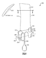
- FIG. 2 schematically illustrates a rotor 100.
- the rotor 100 includes a blade 110 extending outward from a rim 120 along a blade chord line 112.
- the blade 110 is an airfoil shaped blade with a leading edge 114 and a trailing edge 116.
- the portion of the rotor rim 120 at the leading edge of the blade 110 is referred to as the leading extremity 122.
- the portion of the rotor rim 120 at the trailing edge of the blade 110 is referred to as the trailing extremity 124.
- a bore 130 extends from the rim 120 in the opposite direction of the blade 110.
- the blade 110 In an assembled configuration, such as the gas powered turbine 20 of Figure 1 , the blade 110 extends radially outward into the primary flowpath C, and the bore 130 extends radially inward from the rim 120.
- the bore 130 counters the mass of, and axially balances, the rotor blade 110 according to known rotor construction techniques.
- the peak vibratory stress is primarily concentrated at the trailing extremity 124 of the rim 120.
- the impact of the stress resulting from a stiff-wise bending vibratory mode is primarily located at the trailing extremity 124 of the rim 120.
- a rail 140 extends from the rim 120 opposite the blade 110 at the trailing extremity 124.
- the rail 140 has a radial length X that, in some examples, extends below a self-sustaining radius 102, allowing the rail 140 to at least partially self balance.
- the added material of the rail 140 increases the stiffness of the rim 120 at the rail 140.
- the increased stiffness decreases the impact of the vibratory stresses at the location of the rail 140.
- the rail 140 extends a sufficient axial distance Y to have sufficient out of plane stiffness to reduce vibratory stresses to desired levels. Including the rail 140 absent any other modifications can off-balance the rotor 100.
- the bore 130 is shifted axially, and sized such that the mass of the bore 130 and the single rail 140 together axially balance the mass of the blade 110.
- Protruding from the rail 140 is an arm 150.
- the arm 150 contacts, or connects to, other components within the gas powered turbine 20.
- Protruding from the rim is a web 155.
- the web 155 and the bore 130 are shaped and weighted to tune or reduce steady stresses on the rotor 100.
- the combination of the rail 140 and the web 155 reduces both the stiff wise bending mode stresses and the steady stresses on the rotor 100, thereby lengthening the workable lifespan of the rotor 100. It is understood that the preceding also applies at the leading extremity 122 with the rail 140 in line with that extremity.
- Figure 3 schematically illustrates a second example rotor that can be utilized in the example gas powered turbine 20 of Figure 1 .
- the example rotor 200 of Figure 3 includes a blade 210 extending away from a rim 220 along a chord line 212.
- the blade 210 includes a leading edge 214 and a trailing edge 216.
- a bore 230 extends away from the rim 220 at approximately the center of the rim 220, and provides mass countering and axially balancing affects against the blade 210.
- first rail 260 extends from rim 220 at the leading extremity 222.
- second rail 240 extends from the trailing extremity 224 of the rim 220.
- each of the rails 240, 260 extends beyond a self-sustaining radius 202 of the rotor 200. In alternative examples, the rails 240, 260 do not extend beyond the self-sustaining radius 202.
- An arm 250 extends from the second rail 240 and serves an identical function to the web 150 described above with regards to the example of Figure 2 .
- a web 255 extends from the rim 22 and serves an identical function to the web 155 described above with regard to the example of Figure 2 .
- each of the rails 240, 260 has an axial width X, such that the rail has sufficient out of plane stiffness to reduce vibratory stress to desired levels at the leading extremity 222 (in the case of the first rail 260) and the trailing extremity 224 (in the case of the second rail 240).
- the axial length X of each rail 240, 260 allows the rail to fully stiffen the portion of the rim 220 from which the rail 240, 260 extends.
- the density, shape and distribution of material throughout the rail 240, 260 is referred to as the weight profile of the rail 240, 260.
- Each of the rails 240, 260 is shaped with a specific weight profile that counterbalances the weight profile of the other rail 240, 260.
- the first rail 260 will have a complementary, but not identical, weight profile to cancel out any unbalance introduced by the features of the second rail 240.
- the same principle can be applied in reverse, with the features of the second rail counterbalancing any of the features of the first rail 260.
- the bore 230 can be reserved for counterbalancing the blade 210. Furthermore, the added mass of the rails 240, 260 below the self sustaining radius 202, if it exists, provides at least some counterbalancing effect to the blade 210, allowing the size of the bore 230 to be reduced relative to the size of a bore for a rotor without any rails 240, 260.
- Figure 4 schematically illustrates a third example rotor 200 for the gas powered turbine 20.
- the rotor 300 of Figure 4 is substantially similar to the rotor 200 of Figure 3 , with a blade 310 defining a chord line 312 and extending from a rim 320.
- the blade includes a leading edge 314 and a trailing edge 316.
- the rim 320 includes a leading extremity at the blade leading edge 314 and a trailing extremity 324 at the blade trailing edge 316.
- Two rails 340, 360 may or may not extend radially inward from each of the extremities 322, 324 beyond a self-sustaining radius 302 of the rotor 300.
- a bore 330 further extends radially inward from the rim 320 between the rails 340, 360.
- the leading extremity rail 360 includes an additional balancing feature 370.
- the balancing feature 370 is multiple protrusions 372 and intrusions 374 that are specifically sized and shaped to counterbalance one or more features of the rotor 300. While illustrated on the leading rail 360, the balancing feature 370 can be included on the leading rail 360, the trailing rail 340, or both rails 340, 360.
- the balancing feature 370 can be utilized to supplement the balancing features of the weight profile of the rotor 300.
- balancing feature 370 is illustrated herein as rectangular protrusions, one of skill in the art having the benefit of this disclosure will understand that the particular balancing features can take the form of any shape protrusion including, but not limited to, bumps, divots, pyramids, cylinders, or any other shaped protrusion/intrusion.
- any stage in the compressor section 24 of Figure 1 can be utilized and adapted for any stage in the compressor section 24 of Figure 1 .
- One of skill in the art will further understand that the larger the airfoil 110, 210, 310 to the overall rotor 100, 200, 300, the larger the impact of the vibratory stresses will be on the rim 120, 220, 320.
- the earlier stages of any compressor section 24 or later sections of any turbine section 46 require larger rotors and stators.
- the present disclosure is of particular use in the first stage, or the early stages, of the compressor section 24 or in the last stage, or the later stages, of the turbine section 46 relative to airflow through the gas powered turbine 20.
- example rotors are described within the context of a turbine engine as the gas powered turbine 20, one of skill in the art having the benefit of this disclosure will understand that the rotors can be implanted within any gas powered turbine, including land based turbines, and are not limited to the gas turbine engine example of Figure 1 .
Landscapes
- Engineering & Computer Science (AREA)
- Mechanical Engineering (AREA)
- General Engineering & Computer Science (AREA)
- Physics & Mathematics (AREA)
- Fluid Mechanics (AREA)
- Chemical & Material Sciences (AREA)
- Combustion & Propulsion (AREA)
- Turbine Rotor Nozzle Sealing (AREA)
- Structures Of Non-Positive Displacement Pumps (AREA)
Applications Claiming Priority (1)
| Application Number | Priority Date | Filing Date | Title |
|---|---|---|---|
| US201462014757P | 2014-06-20 | 2014-06-20 |
Publications (2)
| Publication Number | Publication Date |
|---|---|
| EP2957792A1 true EP2957792A1 (de) | 2015-12-23 |
| EP2957792B1 EP2957792B1 (de) | 2020-07-29 |
Family
ID=53385561
Family Applications (1)
| Application Number | Title | Priority Date | Filing Date |
|---|---|---|---|
| EP15171747.7A Active EP2957792B1 (de) | 2014-06-20 | 2015-06-11 | Rotor mit reduzierter schwingungsreaktion für eine gasbetriebene turbine |
Country Status (2)
| Country | Link |
|---|---|
| US (1) | US9803481B2 (de) |
| EP (1) | EP2957792B1 (de) |
Cited By (2)
| Publication number | Priority date | Publication date | Assignee | Title |
|---|---|---|---|---|
| WO2017114644A1 (de) * | 2015-12-28 | 2017-07-06 | Siemens Aktiengesellschaft | Verfahren zum herstellen eines grundkörpers einer turbinenschaufel |
| EP3301256A1 (de) * | 2016-09-23 | 2018-04-04 | MTU Aero Engines GmbH | Rotorstufe für eine strömungsmaschine, rotortrommel und rotor |
Families Citing this family (3)
| Publication number | Priority date | Publication date | Assignee | Title |
|---|---|---|---|---|
| CN113931872B (zh) * | 2021-12-15 | 2022-03-18 | 成都中科翼能科技有限公司 | 一种燃气轮机压气机的双层鼓筒加强型转子结构 |
| DE102022101762A1 (de) * | 2022-01-26 | 2023-07-27 | MTU Aero Engines AG | Rotor mit einem Wuchtflansch, Rotoranordnung mit zumindest einem Rotor und Strömungsmaschine mit zumindest einem Rotor oder mit einer Rotoranordnung |
| US12228052B2 (en) * | 2023-07-19 | 2025-02-18 | Pratt & Whitney Canada Corp. | Integrally bladed rotor with increased rim bending stiffness |
Citations (8)
| Publication number | Priority date | Publication date | Assignee | Title |
|---|---|---|---|---|
| US4817455A (en) * | 1987-10-15 | 1989-04-04 | United Technologies Corporation | Gas turbine engine balancing |
| US4961686A (en) * | 1989-02-17 | 1990-10-09 | General Electric Company | F.O.D.-resistant blade |
| US5108261A (en) * | 1991-07-11 | 1992-04-28 | United Technologies Corporation | Compressor disk assembly |
| JPH04285341A (ja) * | 1991-03-15 | 1992-10-09 | Mitsubishi Heavy Ind Ltd | 回転体のカウンターウエイト装置 |
| EP1452687A2 (de) * | 2003-02-27 | 2004-09-01 | Rolls-Royce Plc | Rotorauswuchtung |
| EP1862698A2 (de) * | 2006-06-01 | 2007-12-05 | Rolls-Royce plc | Korrektur eines Rotorenungleichgewichts |
| EP2009238A1 (de) * | 2007-06-26 | 2008-12-31 | Snecma | Laufrad für Turbostrahltriebwerk und damit ausgestattetes Turbostrahltriebwerk |
| EP2677119A2 (de) * | 2012-06-20 | 2013-12-25 | Rolls-Royce plc | Rotorauswuchtverfahren |
Family Cites Families (7)
| Publication number | Priority date | Publication date | Assignee | Title |
|---|---|---|---|---|
| US4848182A (en) * | 1987-09-08 | 1989-07-18 | United Technologies Corporation | Rotor balance system |
| US4926710A (en) * | 1987-09-08 | 1990-05-22 | United Technologies Corporation | Method of balancing bladed gas turbine engine rotor |
| US6354780B1 (en) * | 2000-09-15 | 2002-03-12 | General Electric Company | Eccentric balanced blisk |
| US7097420B2 (en) | 2004-04-14 | 2006-08-29 | General Electric Company | Methods and apparatus for assembling gas turbine engines |
| FR2930595B1 (fr) * | 2008-04-24 | 2011-10-14 | Snecma | Rotor de soufflante d'une turbomachine ou d'un moteur d'essai |
| JP2012047101A (ja) | 2010-08-26 | 2012-03-08 | Ihi Corp | ターボ機械 |
| US9045990B2 (en) * | 2011-05-26 | 2015-06-02 | United Technologies Corporation | Integrated ceramic matrix composite rotor disk geometry for a gas turbine engine |
-
2015
- 2015-06-11 EP EP15171747.7A patent/EP2957792B1/de active Active
- 2015-06-16 US US14/740,316 patent/US9803481B2/en active Active
Patent Citations (8)
| Publication number | Priority date | Publication date | Assignee | Title |
|---|---|---|---|---|
| US4817455A (en) * | 1987-10-15 | 1989-04-04 | United Technologies Corporation | Gas turbine engine balancing |
| US4961686A (en) * | 1989-02-17 | 1990-10-09 | General Electric Company | F.O.D.-resistant blade |
| JPH04285341A (ja) * | 1991-03-15 | 1992-10-09 | Mitsubishi Heavy Ind Ltd | 回転体のカウンターウエイト装置 |
| US5108261A (en) * | 1991-07-11 | 1992-04-28 | United Technologies Corporation | Compressor disk assembly |
| EP1452687A2 (de) * | 2003-02-27 | 2004-09-01 | Rolls-Royce Plc | Rotorauswuchtung |
| EP1862698A2 (de) * | 2006-06-01 | 2007-12-05 | Rolls-Royce plc | Korrektur eines Rotorenungleichgewichts |
| EP2009238A1 (de) * | 2007-06-26 | 2008-12-31 | Snecma | Laufrad für Turbostrahltriebwerk und damit ausgestattetes Turbostrahltriebwerk |
| EP2677119A2 (de) * | 2012-06-20 | 2013-12-25 | Rolls-Royce plc | Rotorauswuchtverfahren |
Cited By (6)
| Publication number | Priority date | Publication date | Assignee | Title |
|---|---|---|---|---|
| WO2017114644A1 (de) * | 2015-12-28 | 2017-07-06 | Siemens Aktiengesellschaft | Verfahren zum herstellen eines grundkörpers einer turbinenschaufel |
| CN108474254A (zh) * | 2015-12-28 | 2018-08-31 | 西门子股份公司 | 用于制造涡轮动叶的基体的方法 |
| CN108474254B (zh) * | 2015-12-28 | 2020-04-24 | 西门子股份公司 | 用于制造涡轮动叶的基体的方法 |
| US10669857B2 (en) | 2015-12-28 | 2020-06-02 | Siemens Aktiengesellschaft | Method for producing a base body of a turbine blade |
| EP3301256A1 (de) * | 2016-09-23 | 2018-04-04 | MTU Aero Engines GmbH | Rotorstufe für eine strömungsmaschine, rotortrommel und rotor |
| US10458434B2 (en) | 2016-09-23 | 2019-10-29 | MTU Aero Engines AG | Rotor stage for a turbomachine, rotor drum, and rotor |
Also Published As
| Publication number | Publication date |
|---|---|
| US9803481B2 (en) | 2017-10-31 |
| EP2957792B1 (de) | 2020-07-29 |
| US20150369045A1 (en) | 2015-12-24 |
Similar Documents
| Publication | Publication Date | Title |
|---|---|---|
| US10240529B2 (en) | Gas turbine engine aft bearing arrangement | |
| US10808543B2 (en) | Rotors with modulus mistuned airfoils | |
| US9828864B2 (en) | Fan blade tall dovetail for individually bladed rotors | |
| US9803481B2 (en) | Reduced vibratory response rotor for a gas powered turbine | |
| US10316670B2 (en) | Hollow blade having internal damper | |
| EP3049655B1 (de) | Lageranordnung für einen gasturbinenmotor, die radialvibrationen in axialvibrationen verwandelt | |
| US12049846B2 (en) | Shaft bearing positioning in a gas turbine engine | |
| US10247003B2 (en) | Balanced rotating component for a gas powered engine | |
| US20210189962A1 (en) | Shaft bearing arrangement | |
| EP3712391B1 (de) | Dämpfungstrebenanordnung und verfahren zu deren herstellung | |
| US11248538B2 (en) | Radially fastened fixed-variable vane system | |
| EP3670942A1 (de) | Lageranordnung mit aktiver schwingungsregelung | |
| US20210189908A1 (en) | Gas turbine engine with a three bearings shaft | |
| US10876416B2 (en) | Vane segment with ribs | |
| US11448164B2 (en) | Shaft bearings for gas turbine engine | |
| US10533581B2 (en) | Stator with support structure feature for tuned airfoil | |
| US10119410B2 (en) | Vane seal system having spring positively locating seal member in axial direction | |
| US9938854B2 (en) | Gas turbine engine airfoil curvature |
Legal Events
| Date | Code | Title | Description |
|---|---|---|---|
| PUAI | Public reference made under article 153(3) epc to a published international application that has entered the european phase |
Free format text: ORIGINAL CODE: 0009012 |
|
| AK | Designated contracting states |
Kind code of ref document: A1 Designated state(s): AL AT BE BG CH CY CZ DE DK EE ES FI FR GB GR HR HU IE IS IT LI LT LU LV MC MK MT NL NO PL PT RO RS SE SI SK SM TR |
|
| AX | Request for extension of the european patent |
Extension state: BA ME |
|
| 17P | Request for examination filed |
Effective date: 20160623 |
|
| RBV | Designated contracting states (corrected) |
Designated state(s): AL AT BE BG CH CY CZ DE DK EE ES FI FR GB GR HR HU IE IS IT LI LT LU LV MC MK MT NL NO PL PT RO RS SE SI SK SM TR |
|
| RAP1 | Party data changed (applicant data changed or rights of an application transferred) |
Owner name: UNITED TECHNOLOGIES CORPORATION |
|
| STAA | Information on the status of an ep patent application or granted ep patent |
Free format text: STATUS: EXAMINATION IS IN PROGRESS |
|
| 17Q | First examination report despatched |
Effective date: 20180718 |
|
| GRAP | Despatch of communication of intention to grant a patent |
Free format text: ORIGINAL CODE: EPIDOSNIGR1 |
|
| STAA | Information on the status of an ep patent application or granted ep patent |
Free format text: STATUS: GRANT OF PATENT IS INTENDED |
|
| INTG | Intention to grant announced |
Effective date: 20200128 |
|
| GRAS | Grant fee paid |
Free format text: ORIGINAL CODE: EPIDOSNIGR3 |
|
| GRAA | (expected) grant |
Free format text: ORIGINAL CODE: 0009210 |
|
| STAA | Information on the status of an ep patent application or granted ep patent |
Free format text: STATUS: THE PATENT HAS BEEN GRANTED |
|
| AK | Designated contracting states |
Kind code of ref document: B1 Designated state(s): AL AT BE BG CH CY CZ DE DK EE ES FI FR GB GR HR HU IE IS IT LI LT LU LV MC MK MT NL NO PL PT RO RS SE SI SK SM TR |
|
| REG | Reference to a national code |
Ref country code: CH Ref legal event code: EP |
|
| REG | Reference to a national code |
Ref country code: DE Ref legal event code: R096 Ref document number: 602015056408 Country of ref document: DE |
|
| REG | Reference to a national code |
Ref country code: AT Ref legal event code: REF Ref document number: 1296173 Country of ref document: AT Kind code of ref document: T Effective date: 20200815 |
|
| REG | Reference to a national code |
Ref country code: IE Ref legal event code: FG4D |
|
| REG | Reference to a national code |
Ref country code: LT Ref legal event code: MG4D |
|
| REG | Reference to a national code |
Ref country code: NL Ref legal event code: MP Effective date: 20200729 |
|
| REG | Reference to a national code |
Ref country code: AT Ref legal event code: MK05 Ref document number: 1296173 Country of ref document: AT Kind code of ref document: T Effective date: 20200729 |
|
| PG25 | Lapsed in a contracting state [announced via postgrant information from national office to epo] |
Ref country code: GR Free format text: LAPSE BECAUSE OF FAILURE TO SUBMIT A TRANSLATION OF THE DESCRIPTION OR TO PAY THE FEE WITHIN THE PRESCRIBED TIME-LIMIT Effective date: 20201030 Ref country code: FI Free format text: LAPSE BECAUSE OF FAILURE TO SUBMIT A TRANSLATION OF THE DESCRIPTION OR TO PAY THE FEE WITHIN THE PRESCRIBED TIME-LIMIT Effective date: 20200729 Ref country code: PT Free format text: LAPSE BECAUSE OF FAILURE TO SUBMIT A TRANSLATION OF THE DESCRIPTION OR TO PAY THE FEE WITHIN THE PRESCRIBED TIME-LIMIT Effective date: 20201130 Ref country code: NO Free format text: LAPSE BECAUSE OF FAILURE TO SUBMIT A TRANSLATION OF THE DESCRIPTION OR TO PAY THE FEE WITHIN THE PRESCRIBED TIME-LIMIT Effective date: 20201029 Ref country code: AT Free format text: LAPSE BECAUSE OF FAILURE TO SUBMIT A TRANSLATION OF THE DESCRIPTION OR TO PAY THE FEE WITHIN THE PRESCRIBED TIME-LIMIT Effective date: 20200729 Ref country code: ES Free format text: LAPSE BECAUSE OF FAILURE TO SUBMIT A TRANSLATION OF THE DESCRIPTION OR TO PAY THE FEE WITHIN THE PRESCRIBED TIME-LIMIT Effective date: 20200729 Ref country code: BG Free format text: LAPSE BECAUSE OF FAILURE TO SUBMIT A TRANSLATION OF THE DESCRIPTION OR TO PAY THE FEE WITHIN THE PRESCRIBED TIME-LIMIT Effective date: 20201029 Ref country code: SE Free format text: LAPSE BECAUSE OF FAILURE TO SUBMIT A TRANSLATION OF THE DESCRIPTION OR TO PAY THE FEE WITHIN THE PRESCRIBED TIME-LIMIT Effective date: 20200729 Ref country code: LT Free format text: LAPSE BECAUSE OF FAILURE TO SUBMIT A TRANSLATION OF THE DESCRIPTION OR TO PAY THE FEE WITHIN THE PRESCRIBED TIME-LIMIT Effective date: 20200729 Ref country code: HR Free format text: LAPSE BECAUSE OF FAILURE TO SUBMIT A TRANSLATION OF THE DESCRIPTION OR TO PAY THE FEE WITHIN THE PRESCRIBED TIME-LIMIT Effective date: 20200729 |
|
| PG25 | Lapsed in a contracting state [announced via postgrant information from national office to epo] |
Ref country code: PL Free format text: LAPSE BECAUSE OF FAILURE TO SUBMIT A TRANSLATION OF THE DESCRIPTION OR TO PAY THE FEE WITHIN THE PRESCRIBED TIME-LIMIT Effective date: 20200729 Ref country code: RS Free format text: LAPSE BECAUSE OF FAILURE TO SUBMIT A TRANSLATION OF THE DESCRIPTION OR TO PAY THE FEE WITHIN THE PRESCRIBED TIME-LIMIT Effective date: 20200729 Ref country code: LV Free format text: LAPSE BECAUSE OF FAILURE TO SUBMIT A TRANSLATION OF THE DESCRIPTION OR TO PAY THE FEE WITHIN THE PRESCRIBED TIME-LIMIT Effective date: 20200729 Ref country code: IS Free format text: LAPSE BECAUSE OF FAILURE TO SUBMIT A TRANSLATION OF THE DESCRIPTION OR TO PAY THE FEE WITHIN THE PRESCRIBED TIME-LIMIT Effective date: 20201129 |
|
| RAP2 | Party data changed (patent owner data changed or rights of a patent transferred) |
Owner name: RAYTHEON TECHNOLOGIES CORPORATION |
|
| PG25 | Lapsed in a contracting state [announced via postgrant information from national office to epo] |
Ref country code: NL Free format text: LAPSE BECAUSE OF FAILURE TO SUBMIT A TRANSLATION OF THE DESCRIPTION OR TO PAY THE FEE WITHIN THE PRESCRIBED TIME-LIMIT Effective date: 20200729 |
|
| PG25 | Lapsed in a contracting state [announced via postgrant information from national office to epo] |
Ref country code: EE Free format text: LAPSE BECAUSE OF FAILURE TO SUBMIT A TRANSLATION OF THE DESCRIPTION OR TO PAY THE FEE WITHIN THE PRESCRIBED TIME-LIMIT Effective date: 20200729 Ref country code: SM Free format text: LAPSE BECAUSE OF FAILURE TO SUBMIT A TRANSLATION OF THE DESCRIPTION OR TO PAY THE FEE WITHIN THE PRESCRIBED TIME-LIMIT Effective date: 20200729 Ref country code: RO Free format text: LAPSE BECAUSE OF FAILURE TO SUBMIT A TRANSLATION OF THE DESCRIPTION OR TO PAY THE FEE WITHIN THE PRESCRIBED TIME-LIMIT Effective date: 20200729 Ref country code: IT Free format text: LAPSE BECAUSE OF FAILURE TO SUBMIT A TRANSLATION OF THE DESCRIPTION OR TO PAY THE FEE WITHIN THE PRESCRIBED TIME-LIMIT Effective date: 20200729 Ref country code: DK Free format text: LAPSE BECAUSE OF FAILURE TO SUBMIT A TRANSLATION OF THE DESCRIPTION OR TO PAY THE FEE WITHIN THE PRESCRIBED TIME-LIMIT Effective date: 20200729 Ref country code: CZ Free format text: LAPSE BECAUSE OF FAILURE TO SUBMIT A TRANSLATION OF THE DESCRIPTION OR TO PAY THE FEE WITHIN THE PRESCRIBED TIME-LIMIT Effective date: 20200729 |
|
| REG | Reference to a national code |
Ref country code: DE Ref legal event code: R097 Ref document number: 602015056408 Country of ref document: DE |
|
| PG25 | Lapsed in a contracting state [announced via postgrant information from national office to epo] |
Ref country code: AL Free format text: LAPSE BECAUSE OF FAILURE TO SUBMIT A TRANSLATION OF THE DESCRIPTION OR TO PAY THE FEE WITHIN THE PRESCRIBED TIME-LIMIT Effective date: 20200729 |
|
| PLBE | No opposition filed within time limit |
Free format text: ORIGINAL CODE: 0009261 |
|
| STAA | Information on the status of an ep patent application or granted ep patent |
Free format text: STATUS: NO OPPOSITION FILED WITHIN TIME LIMIT |
|
| PG25 | Lapsed in a contracting state [announced via postgrant information from national office to epo] |
Ref country code: SK Free format text: LAPSE BECAUSE OF FAILURE TO SUBMIT A TRANSLATION OF THE DESCRIPTION OR TO PAY THE FEE WITHIN THE PRESCRIBED TIME-LIMIT Effective date: 20200729 |
|
| 26N | No opposition filed |
Effective date: 20210430 |
|
| PG25 | Lapsed in a contracting state [announced via postgrant information from national office to epo] |
Ref country code: SI Free format text: LAPSE BECAUSE OF FAILURE TO SUBMIT A TRANSLATION OF THE DESCRIPTION OR TO PAY THE FEE WITHIN THE PRESCRIBED TIME-LIMIT Effective date: 20200729 |
|
| PG25 | Lapsed in a contracting state [announced via postgrant information from national office to epo] |
Ref country code: MC Free format text: LAPSE BECAUSE OF FAILURE TO SUBMIT A TRANSLATION OF THE DESCRIPTION OR TO PAY THE FEE WITHIN THE PRESCRIBED TIME-LIMIT Effective date: 20200729 |
|
| REG | Reference to a national code |
Ref country code: CH Ref legal event code: PL |
|
| REG | Reference to a national code |
Ref country code: BE Ref legal event code: MM Effective date: 20210630 |
|
| PG25 | Lapsed in a contracting state [announced via postgrant information from national office to epo] |
Ref country code: LU Free format text: LAPSE BECAUSE OF NON-PAYMENT OF DUE FEES Effective date: 20210611 |
|
| PG25 | Lapsed in a contracting state [announced via postgrant information from national office to epo] |
Ref country code: LI Free format text: LAPSE BECAUSE OF NON-PAYMENT OF DUE FEES Effective date: 20210630 Ref country code: IE Free format text: LAPSE BECAUSE OF NON-PAYMENT OF DUE FEES Effective date: 20210611 Ref country code: CH Free format text: LAPSE BECAUSE OF NON-PAYMENT OF DUE FEES Effective date: 20210630 |
|
| PG25 | Lapsed in a contracting state [announced via postgrant information from national office to epo] |
Ref country code: BE Free format text: LAPSE BECAUSE OF NON-PAYMENT OF DUE FEES Effective date: 20210630 |
|
| PG25 | Lapsed in a contracting state [announced via postgrant information from national office to epo] |
Ref country code: HU Free format text: LAPSE BECAUSE OF FAILURE TO SUBMIT A TRANSLATION OF THE DESCRIPTION OR TO PAY THE FEE WITHIN THE PRESCRIBED TIME-LIMIT; INVALID AB INITIO Effective date: 20150611 |
|
| P01 | Opt-out of the competence of the unified patent court (upc) registered |
Effective date: 20230520 |
|
| PG25 | Lapsed in a contracting state [announced via postgrant information from national office to epo] |
Ref country code: CY Free format text: LAPSE BECAUSE OF FAILURE TO SUBMIT A TRANSLATION OF THE DESCRIPTION OR TO PAY THE FEE WITHIN THE PRESCRIBED TIME-LIMIT Effective date: 20200729 |
|
| PG25 | Lapsed in a contracting state [announced via postgrant information from national office to epo] |
Ref country code: MK Free format text: LAPSE BECAUSE OF FAILURE TO SUBMIT A TRANSLATION OF THE DESCRIPTION OR TO PAY THE FEE WITHIN THE PRESCRIBED TIME-LIMIT Effective date: 20200729 |
|
| PG25 | Lapsed in a contracting state [announced via postgrant information from national office to epo] |
Ref country code: MT Free format text: LAPSE BECAUSE OF FAILURE TO SUBMIT A TRANSLATION OF THE DESCRIPTION OR TO PAY THE FEE WITHIN THE PRESCRIBED TIME-LIMIT Effective date: 20200729 |
|
| PGFP | Annual fee paid to national office [announced via postgrant information from national office to epo] |
Ref country code: DE Payment date: 20250520 Year of fee payment: 11 |
|
| PGFP | Annual fee paid to national office [announced via postgrant information from national office to epo] |
Ref country code: GB Payment date: 20250520 Year of fee payment: 11 |
|
| PGFP | Annual fee paid to national office [announced via postgrant information from national office to epo] |
Ref country code: FR Payment date: 20250520 Year of fee payment: 11 |
|
| REG | Reference to a national code |
Ref country code: DE Ref legal event code: R081 Ref document number: 602015056408 Country of ref document: DE Owner name: RTX CORPORATION (N.D.GES.D. STAATES DELAWARE),, US Free format text: FORMER OWNER: UNITED TECHNOLOGIES CORPORATION, FARMINGTON, CONN., US |
|
| PG25 | Lapsed in a contracting state [announced via postgrant information from national office to epo] |
Ref country code: TR Free format text: LAPSE BECAUSE OF FAILURE TO SUBMIT A TRANSLATION OF THE DESCRIPTION OR TO PAY THE FEE WITHIN THE PRESCRIBED TIME-LIMIT Effective date: 20200729 |