EP2957802B1 - Vanne multi-voies a actionnement en deux etapes - Google Patents
Vanne multi-voies a actionnement en deux etapes Download PDFInfo
- Publication number
- EP2957802B1 EP2957802B1 EP15401048.2A EP15401048A EP2957802B1 EP 2957802 B1 EP2957802 B1 EP 2957802B1 EP 15401048 A EP15401048 A EP 15401048A EP 2957802 B1 EP2957802 B1 EP 2957802B1
- Authority
- EP
- European Patent Office
- Prior art keywords
- valve
- actuator
- central axis
- switching shaft
- lever
- Prior art date
- Legal status (The legal status is an assumption and is not a legal conclusion. Google has not performed a legal analysis and makes no representation as to the accuracy of the status listed.)
- Active
Links
Images






Classifications
-
- F—MECHANICAL ENGINEERING; LIGHTING; HEATING; WEAPONS; BLASTING
- F16—ENGINEERING ELEMENTS AND UNITS; GENERAL MEASURES FOR PRODUCING AND MAINTAINING EFFECTIVE FUNCTIONING OF MACHINES OR INSTALLATIONS; THERMAL INSULATION IN GENERAL
- F16K—VALVES; TAPS; COCKS; ACTUATING-FLOATS; DEVICES FOR VENTING OR AERATING
- F16K11/00—Multiple-way valves, e.g. mixing valves; Pipe fittings incorporating such valves
- F16K11/10—Multiple-way valves, e.g. mixing valves; Pipe fittings incorporating such valves with two or more closure members not moving as a unit
- F16K11/14—Multiple-way valves, e.g. mixing valves; Pipe fittings incorporating such valves with two or more closure members not moving as a unit operated by one actuating member, e.g. a handle
- F16K11/18—Multiple-way valves, e.g. mixing valves; Pipe fittings incorporating such valves with two or more closure members not moving as a unit operated by one actuating member, e.g. a handle with separate operating movements for separate closure members
-
- F—MECHANICAL ENGINEERING; LIGHTING; HEATING; WEAPONS; BLASTING
- F16—ENGINEERING ELEMENTS AND UNITS; GENERAL MEASURES FOR PRODUCING AND MAINTAINING EFFECTIVE FUNCTIONING OF MACHINES OR INSTALLATIONS; THERMAL INSULATION IN GENERAL
- F16K—VALVES; TAPS; COCKS; ACTUATING-FLOATS; DEVICES FOR VENTING OR AERATING
- F16K11/00—Multiple-way valves, e.g. mixing valves; Pipe fittings incorporating such valves
- F16K11/10—Multiple-way valves, e.g. mixing valves; Pipe fittings incorporating such valves with two or more closure members not moving as a unit
- F16K11/14—Multiple-way valves, e.g. mixing valves; Pipe fittings incorporating such valves with two or more closure members not moving as a unit operated by one actuating member, e.g. a handle
-
- F—MECHANICAL ENGINEERING; LIGHTING; HEATING; WEAPONS; BLASTING
- F16—ENGINEERING ELEMENTS AND UNITS; GENERAL MEASURES FOR PRODUCING AND MAINTAINING EFFECTIVE FUNCTIONING OF MACHINES OR INSTALLATIONS; THERMAL INSULATION IN GENERAL
- F16K—VALVES; TAPS; COCKS; ACTUATING-FLOATS; DEVICES FOR VENTING OR AERATING
- F16K31/00—Actuating devices; Operating means; Releasing devices
- F16K31/44—Mechanical actuating means
- F16K31/52—Mechanical actuating means with crank, eccentric, or cam
- F16K31/524—Mechanical actuating means with crank, eccentric, or cam with a cam
- F16K31/52408—Mechanical actuating means with crank, eccentric, or cam with a cam comprising a lift valve
- F16K31/52416—Mechanical actuating means with crank, eccentric, or cam with a cam comprising a lift valve comprising a multiple-way lift valve
-
- A—HUMAN NECESSITIES
- A01—AGRICULTURE; FORESTRY; ANIMAL HUSBANDRY; HUNTING; TRAPPING; FISHING
- A01C—PLANTING; SOWING; FERTILISING
- A01C23/00—Distributing devices specially adapted for liquid manure or other fertilising liquid, including ammonia, e.g. transport tanks or sprinkling wagons
- A01C23/007—Metering or regulating systems
Definitions
- the present invention relates to a multi-way valve that can be used in particular for agricultural sprayers, and that a supply port for a pressure line, N-load ports, N-valve elements, each of which can produce a fluid-permeable connection between the supply port and at least one of the N-load ports and an actuator for selecting at least one of the N-valve elements and for moving the selected valve element to an open position or a closed position.
- a supply port for a pressure line N-load ports, N-valve elements, each of which can produce a fluid-permeable connection between the supply port and at least one of the N-load ports and an actuator for selecting at least one of the N-valve elements and for moving the selected valve element to an open position or a closed position.
- Such multi-way valves for landscape sprayers are also known as pressure tap.
- a multi-way valve according to the preamble of claim 1 is characterized by the NL 59688 C known.
- a multi-way valve in particular for agricultural sprayers, is for example from the DE 10 2006 006 985 A1 known.
- This publication for a German patent application discloses a multi-way valve with a housing to which a trained as a pressure line access line and several outlet lines are connected. A, the number of outlet lines corresponding number of valve bodies are arranged in a circle around a rotatably mounted central actuator. To select a particular valve or a particular outlet line, the central actuating element is moved via the switching shaft to the corresponding valve to be actuated. The arrangement is such that, during the rotational movement, the central actuating element pushes the valve body outwards in such a way that a connection between the pressure line and the outlet line corresponding to the valve is released.
- valves If a valve is to be selected in which there are a plurality of valves between the current position of the actuating element and the valve to be selected, the actuating element must be moved past these valve elements, these valve elements being actuated briefly.
- the actuating element When selecting a particular valve therefore usually several valves are short-term operated, ie the corresponding outgoing lines are briefly put under pressure. This also means that liquid gets into discharge lines, where this was not intended. Furthermore, this also means an undesirable loss of energy during the switching process, since the short-term pressure loss must be compensated by the derivative in the unwanted outgoing lines.
- This prior art shows a multi-way valve with a housing, in which a suction line and according to the number of ways several leads, which are associated with the mouth of the supply lines closing and releasing valve body, open.
- the multi-way valve shown there also has a central actuating element, by means of which the valve body are displaceable in a closed or open position.
- the leads are arranged star-shaped opening into the housing.
- the multi-way valve has a central actuating element to be actuated by a hand lever, by means of which the valve body associated with the connecting lines can be actuated.
- the valve bodies are movable radially outwards perpendicular to the axis of rotation of the central actuating element and are held in a closed position, ie pressed radially inwards, by a spring.
- the central actuator consists of a switching shaft to which an actuating cam is mounted. By turning the selector shaft, the cam is positioned to a valve element. The cam then pushes the valve member from its closed position against the spring pressure to an open position.
- a multiway valve comprising: a supply port; N-consumer connections; N-valve elements, each of which can produce a fluid-permeable connection between the supply port and at least one of the N-load ports; and an actuator for selecting at least one of the N-valve elements and operating the selected valve element in an open position or a closed position.
- the multi-way valve according to the invention is characterized in that the actuator and the N-valve elements are designed and arranged so that the selection and the actuation of one of the N valve elements is independent in two stages, so that none of the N valve elements during the selection of the at least one valve element is pressed.
- the actuator has a projection extending radially outward with respect to a central axis; and each of the N-valve elements has a recess into which the projection of the actuator can engage.
- the projection of the actuator passes unhindered in selecting the valve element, the non-selected valve elements and on the other hand, the recess serves as an engagement for the projection, so that the actuator can actuate the valve element in an open or closed position.
- the projection of the actuator is formed so that it extends over a radial region which allows either the operation of a single valve element or the simultaneous actuation of two adjacent valve elements. That is, the projection of the actuator is formed with a sufficient width, the projection of the actuator can engage in an intermediate position between two adjacent valve elements in both recesses, thus enabling a simultaneous actuation of the adjacent valve elements.
- the N-valve elements are arranged circular about a central axis in respective cavities of a multiway valve housing such that the N-valve elements are independently movable parallel to the central axis within the corresponding cavity between an open position and a closed position.
- the actuator performs a rotational movement in the valve selection.
- the actuator executes a movement parallel to the axis of rotation (central axis). Since the direction of movement for actuating the valve is perpendicular to the direction of movement of the actuator in the valve selection, it is possible with this arrangement to carry out a selection of valve elements independently of their actuation.
- this can be realized by the switching member is rotatable about the central axis and slidably mounted parallel to the central axis. That by rotating the actuator about the central axis, a valve can be selected and by moving the actuator parallel to the central axis a selected valve can be actuated. The rotational movement and the vertical movement of the actuator can be performed independently.
- the multi-way valve further comprises a coaxially arranged to the central axis and rotatably mounted relative to the multi-way valve housing shift shaft, the actuator relative to the shift shaft against rotation but parallel to the central axis is movably connected to the shift shaft, so that the actuator by the shift shaft to the central axis can be rotated to select at least one of the N-valve elements; and a displacement device for displacing the actuator parallel to the central axis relative to the switching shaft, so that the actuator through the
- Shifting means can be displaced relative to the switching shaft along the central axis between a first position corresponding to a closed valve and a second position corresponding to an open valve to open or close the at least one selected valve element.
- the selection of a valve element and the operation of the selected valve element can be realized independently, in which the actuator can be rotated via a switching shaft for selecting and in which the actuator can be displaced with a displacement device parallel to the central axis.
- the two elements "shift shaft” and "displacement device” allow each independently operable movement of the actuator in the axial direction and in the direction of rotation.
- the actuator may be at least partially designed as a hollow cylinder, wherein the hollow cylinder receives the switching shaft. That the actuator is arranged coaxially around the shift shaft.
- the actuator and the N-valve elements are configured and arranged such that the selector shaft can only be rotated when the actuator is in the first position.
- a selection of a valve can only take place when all the valve elements have a defined state. This ensures the operational safety of the valve, since no undefined switching states can occur, as a result of which the switching mechanism may possibly jam.
- the multi-way valve may be configured so that all N-valve elements are in the closed position when the supply port is under pressure. This means that the valve elements normally (ie, when the actuator is in the first position) are closed and must be actively opened with the actuator when a connection between the supply port and a Consumer connection to be produced. Since the valves are normally closed, no undefined valve state can arise in the selection of a valve element, so that the functionality of the multi-way valve is ensured.
- the multiway valve further includes at least one biasing member that holds at least one of the N valve members in a closed position unless actuated by the actuator.
- the biasing element ensures that the valve element is even in a defined, preferably a closed position when no pressure is applied to the supply terminal. This measure also serves to improve the reliability of the multi-way valve.
- each of the N valve elements is equipped with a biasing element.
- the multiway valve further includes means for selecting a valve member and actuating the selected valve member.
- This device for selecting and operating can be, for example, a manually operable lever, which is attached via a pin to a driver at the end of the switching shaft, so that the lever is rotatable perpendicular to the central axis with the pin as a rotation axis and parallel to the central axis relative to Shift shaft is secured against rotation, wherein the lever is further attached via a dowel pin at one end of the actuator, so that the actuator relative to the shift shaft with the lever can be moved parallel to the central axis.
- the lever with the switching shaft and the actuator is mutually connected against rotation, so that can be rotated / positioned with the lever, the projection of the actuator to a specific valve element.
- the lever is further rotatably mounted perpendicular to the selection rotational movement of the driver, so that when turning the lever about the pin axis (perpendicular to the central axis), the actuator can be raised on the cylinder pin on the lever, wherein the lever on the pin in can support the driver.
- the manually operable lever both the selection mechanism and the actuating mechanism for each of the N-valves independently.
- an outer side of a cylindrical portion of the actuator has two superimposed rows each having N notches or optionally 2 x N notches, such that the actuator at a selected valve position or optionally additionally at intermediate positions between two adjacent valve members in an open position or a locked position.
- the lever upon rotation of the lever / control handle in a neutral or closed position for selecting the valve element, the lever can engage in the individual valve positions or optionally also in intermediate positions, so that the switching positions or actuating positions can be easily found. This creates a haptic and acoustic feedback when adjusting the valve positions.
- the multi-way valve comprises at least one sealing ring between the switching shaft and the actuator and a U-ring between the actuator and the housing to seal the pressurized interior of the valve so that no liquid at the gaps between actuator and switching shaft and between the Actuator and the housing can penetrate to the outside.
- the grooved ring also has the advantage that the sealing effect is always better with increasing pressure. Furthermore, the grooved ring can compensate for irregularities and unevenness as well as disturbances in the surface of the housing.
- the device for selecting a valve element comprises a first motor having a first gear mechanism and the device for actuating the selected valve element comprises a second motor having a second gear mechanism.
- the present invention has been made to provide a multiway valve that overcomes the disadvantages of known multiway valves.
- the present invention overcomes the disadvantage that, when selecting a particular valve in a multi-way valve, those valves which are run over in the selection are actuated for a short time. Due to the short-term valve actuations, the corresponding outgoing lines are briefly put under pressure, which leads to unwanted contamination, pressure loss and energy loss during the switching process.
- This problem is inventively solved in that the actuator is designed so that it is possible to separate the selection process and the actuation process, i. independently, for example, by different directions of movement of the actuator for the selection process and the actuation process, so that no valve element is actuated during the selection of a particular valve element. The arrangement and the actuating direction of the valve elements must then be adapted to the directions of movement of the actuator.
- valve members and the actuator are arranged and configured such that valve selection is by rotary movement of the actuator.
- the actuator performs a movement parallel to the axis of rotation. Since the direction of movement for actuating the valve is perpendicular to the direction of movement of the actuator in the selection of the valve, it is possible with this arrangement to carry out a selection of valve elements independently of their actuation.
- valve selection by a rotary movement of the actuator and the actuating movement is parallel to the axis of rotation
- this invention is not limited to these cases.
- the valve selection can be carried out by a rotary movement and the actuation of the valve element takes place by a movement directed radially outwards or inwards in relation to the axis of rotation.
- the valve selection can also be done by a linear Movement of the actuator done.
- the subsequent actuation of the valve element is then carried out by a vertically directed movement of the actuator.
- Fig. 1 shows a 3D perspective view of an embodiment of a multi-way valve 10, which is suitable for an agricultural field sprayer, for manual operation.
- a multi-way valve is also referred to as a pressure tap.
- Fig. 1 shows a two-part housing 50 having an upper housing part 50a and a lower housing part 50b, which are screwed together with screws (not numbered).
- the lower housing part 50b there is a supply connection 30 and a plurality of consumer connections 20.
- the consumer connections 20 are associated with valve elements 40 which are arranged around a central axis (in Fig. 1 not shown) of the multi-way valve 10 are arranged.
- Each consumer port 20 is closed by a separate valve element 40.
- Fig. 1 At the top of the upper housing part 50a star-shaped covers for star-shaped guides of the valve elements 40 can be seen.
- Fig. 1 further shows a manually operable lever 60 with which valves can be selected and opened.
- Fig. 2 shows a view of the multi-way valve from the Fig. 1 from above.
- the manually operable lever 60 is rotatably disposed coaxially with the central housing axis A at the top of the housing relative to the housing.
- Six valve elements 40-1, 40-2, 40-3, 40-4, 40-5 and 40-6 are arranged in a circle around the central axis A in the valve housing 50.
- Reference numerals which are identical to reference numerals in FIG Fig. 1 same features. This also applies to all following figures. In order to avoid repetition, the technical feature belonging to the reference character is usually described at the first occurrence and dispensed with further repetitions in the following figures.
- the lever 60 can be selected by turning the axis A individual valves.
- the dash-dotted lines in the Fig. 2 indicate positions for possible positions of the lever 60.
- the Fig. 2 shows a position of the lever 60 at the position ZS1. This position corresponds to an intermediate position between the valve elements 40-1 and 40-2. In this intermediate position, the valve elements 40-1 and 40-2 can be operated simultaneously, as in conjunction with Fig. 8 is explained in more detail. Analogously, intermediate positions between two valves can also be selected in the intermediate positions ZS2, ZS3, ZS4 and ZS5.
- the positions S1, S2, S3, S4, S5 and S6 mean that the lever 60, the valve element 40-1 (S1), 40-2 (S2), 40-3 (S3), 40-4 (S4), 40th -5 (S5) or 40-6 (S6).
- the positions ZS1, ZS2, ZS3, ZS4, ZS5, ZS6 and ZS7 are positions for intermediate positions.
- the NS position is a neutral position where no valve is selected.
- valve element 40-1 to 40-6 are closed. That is, during the positioning of the actuator (in Fig. 2 not shown) by the lever 60 to one of the positions S1 to S6, NS and ZS1 to ZS7 none of the six consumer ports 20 and the associated valve elements 40-1 to 40-6 is run over openly.
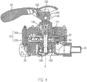
- Fig. 3 shows a section through the multi-way valve along the line II, ie along the line between the lever positions S1 and ZS4, but with the lever 60 to position S1.
- sectional view shows the selected valve element in the closed position.
- the Fig. 3 shows a cross section through the housing 50 with a housing upper part 50 a and a housing lower part 50 b, which are connected to each other via screws (without reference numerals).
- the reference numeral 20 designates again the consumer connections.
- cavities are formed, in which valve body 42 are located. The cavities are formed so that the valve body 42 can move vertically, ie parallel to the central axis A.
- Each valve body 42 has at the bottom a seal 44 and centering 43rd on.
- the valve body 42 has four pins.
- the valves are centered by the four pins on the bottom in the bottom of the housing.
- One of the pins serves as an alignment aid of the valve during assembly.
- two strips are molded in the outflow openings (in Fig. 3 not visible), in which the pin is guided.
- the seal 44 seals the discharge funnel to the consumer port 20 and can compensate for irregularities and unevenness as well as disturbances in the surface of the housing.
- valve body 42 is pressurized, the valve body 42 is pushed down, so that the seal 44, for example, a molded-on valve body 42 seal, is pressed against the lower housing part 50 b, so that the load port 20 is sealed.
- a star-shaped valve guide 47 which is received in a star-shaped recess 41 in the upper housing part 50a, together with the centering 43, the valve body 42 in the axial direction parallel to the central axis A both in the upper housing part 50a and in the lower housing part To lead 50b.
- the cavity for receiving the valve body 42 is configured so that in a closed valve position above the valve body cavities 50c and 50d remain free to allow vertical movement of the valve body 42 (parallel to the central axis A).
- valve body 42 In order to securely hold the valve body 42 in a closed position even at a low pressure at the supply connection, in the region of the star-shaped valve guides 47 there is a compression spring which presses the valve body 42 downwards into the closed position.
- the valve body 42 includes a recess 46 into which a projection 100 a of an actuator 100 can engage. In a closed position of the valve body 42, the projection 100a of the actuator 100 can be freely moved past the valve body 42 without actuating the valve, ie the closed valve remains closed.
- the actuator 100 is rotationally connected to a driver 140 which is connected to a manually operable lever 60 so that rotation of the lever 60 about the central axis A causes rotation of the projection 100a of the actuator 100 about the central axis A.
- a driver 140 which is connected to a manually operable lever 60 so that rotation of the lever 60 about the central axis A causes rotation of the projection 100a of the actuator 100 about the central axis A.
- the actuator 100 In the upper part of the actuator 100 are two slots 190, in which the driver 140 engages.
- the slots allow a rotationally secure engagement of the driver 140 in the actuator 100 and on the other hand allow the actuator 100 relative to the driver 140 remains displaceable parallel to the central axis A.
- the driver 140 rests on a switching shaft 120 and is preferably fixedly connected to the switching shaft 120, or may be an integral part of the switching shaft 120 to hold the driver 140 on the housing 50.
- the shift handle 60 is fixed to the driver 140 with a pin 160.
- the pin 160 also serves as a rotation axis for the handle / lever.
- the lever 60 is therefore rotatably mounted relative to the driver 140 about the pin axis of the pin 160.
- the lever 60 is, however, against rotation with respect to the central axis A relative to the driver 140 of the switching shaft 120, so that upon rotation of the lever 60 about the central axis A, the switching shaft 120 is rotated. Since the actuator 100 is also mounted against rotation with respect to the driver 140, rotates when the lever 60 about the central axis A, the actuator 100 with.
- the switching shaft 120 is rotatably supported on a hollow base shaft 110.
- the base shaft has a collar 130 to prevent rotation with at least one recess. In the recess a nose engages (in Fig. 3 not visible), which may be injection-molded in the housing base 50b.
- the base shaft 110 is fixed to the housing base 50b with a nut (not numbered). The base shaft 110 is therefore fixed relative to the housing 50, that is not rotatable.
- the selector shaft 120 Coaxially and freely rotatably connected to the base shaft is the selector shaft 120. Between the selector shaft 120 and the base shaft 110 may be a sliding washer to reduce wear, or the shift shaft 120 is provided with a wear protection.
- the switching shaft 120 and the base shaft 110 form a mutually rotatable unit, which is held together by a screw 170. The screw is inserted from the outside through the hollow-bored base shaft 110.
- the actuator 100 has a portion 100b in the form of a hollow cylinder and the projection 100a protruding therefrom.
- the hollow cylindrical portion 100b is mounted coaxially on the base shaft in the lower region and coaxially on the selector shaft in the upper region.
- the actuator 100 In the neutral (closed) position of the valve body 42, the actuator 100 can be freely rotated with the projection 100a and up to 360 ° about the central axis A, since the lateral recesses 46 in the valve body 42 can pass the projection 100a unhindered.
- At least one seal 195 seals the actuator 100 relative to the switching shaft 120. Furthermore, the actuator 100 is compared to the base shaft 110 by at least one seal 196, for example, an O-ring, sealed.
- the seal between the actuator 100 and housing upper part 50a takes place in accordance with the embodiment Fig. 3 through a grooved ring 170. Through the grooved ring 170, the sealing effect with increasing pressure is getting better. By acting under pressure self-adjustment of the U-ring can compensate for wear. Furthermore, the U-ring can compensate for non-round and uneven surfaces and disturbances in the surface of the housing.
- the grooved ring 170 is positioned in the housing top 50 a and is fixed by a flange 180. The flange 180 is bolted to the housing top 50a with, for example, three thread-forming screws.
- a cylindrical pin 150 for connecting the actuator 100 to the lever 60 so that when the lever 60 is depressed, ie when the lever 60 rotates about the axis of the pin 160, the actuator 100 is lifted by the cylinder pin 150.
- the cam 140 incorporates a vertical slot in which the cylindrical pin 150 is free to move to ensure that the actuator 100 is free to move relative to the stem in a vertical direction (ie parallel to the central axis A).
- two surfaces may be attached (reference numeral 200 in FIG Fig. 4 ), through which the cylinder pin 150 passes, so that the lever 60 is connected via the cylinder pin 150 to the upper part of the actuator 100 and the actuator 100 by the lever 60th can be raised.
- the surfaces 200 lift the actuator 100 by means of the cylindrical pin 150 and the valve is opened.
- the actuator 100 in the open position as in Fig. 4 is shown on the top of the projection 100a of the actuator 100 is a nose 101a, which engages in the open position in a recess 50e of the housing top 50a, so that the actuator 100 is not rotated about the central axis A. can be. This prevents damage to the valve when attempting to change the position of the actuator 100 in the valve open state.
- Fig. 5 shows a section along the line II-II in Fig. 2 , ie along the line between the lever positions NS (neutral position) and ZS 3, ie intermediate position 3 for selecting the valve elements 40-3 and 40-4.
- Fig. 5 shows a ball pressure screw 210 disposed in the flange 180 so that the ball of the ball pressure screw 210 presses radially inwardly against the actuator 100.
- the ball pressure screw 210 can be adjusted (moved) in the flange 180 to adjust the contact pressure of the ball.
- On an outer surface of the cylindrical portion 100b of the actuator 100 are two rows of counterbores 220 and 230. Each valve is represented by a counterbore.
- the ball pressure screw 210 engages in the upper rim of the counterbores 220 in accordance with a particular valve select position. So a haptic and acoustic feedback of the valve position is given.
- the actuator 100 is pulled up and the ball pressure screw 210 snaps into a countersink in the lower ring of the counterbores 230 and fixes the actuator 100 in the open position.
- the holding force of the ball pressure screw 210 can be adjusted.
- the position of the actuator as well the holding force can be further increased by the fact that a detent is mounted in the switching cam for the intended position.
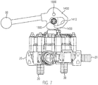
- Fig. 6 and 7 show an alternative embodiment for a hand-operated multiway valve according to the present invention.
- Fig. 6 shows the multiway valve in a closed position
- Fig. 7 shows the multiway valve in an open position. Since the switching forces for opening the actuator are very large, the force required by the short lever 60 and by the simple lifting surface (reference numeral 200 in FIG FIG. 4 ) on the handle / lever 60 may not be applied.
- a multiway valve is provided with an optimized lever 60 for optimizing the axial movement of the actuator.
- the pin 1600 pivot point of the lever 60
- the cylinder pin 1500 for lifting the actuator in FIG.
- the power boost curves 1410 and 1450 will act as support curves 1410 and 1450 on which the cylinder pin 1500 moves as the lever 60 is depressed.
- the slope of the curve 1410 at the beginning of the stroke for example, the first four millimeters stroke, very flat, so that large forces can be transmitted. Since the valve is completely circulated at a stroke of approx. 4 mm and there is almost the same pressure at the top and bottom of the valve body, the valve is in a pressure balanced state. Therefore, the remaining stroke, for example, 6 mm stroke, without additional effort with a greater slope 1450 (see Fig.
- Fig. 8 shows a plan view of the multi-way valve similar to Fig. 2 , but with removed lever and upper housing part.
- the actuator 100 is located in the intermediate position ZS1, that is, the projection 100a of the actuator 100, the valve elements 40-1 and 40-2 simultaneously actuate, ie bring in an open position.
- the protrusion 100a of the actuator 100 protrudes from the cylindrical part 100b of the actuator 100.
- the cylindrical part 100b of the actuator 100 is supported above and around the shift shaft 120.
- the projection 100a of the actuator 100 has a depression 100c, for example, of 4 mm. Since the switching forces are twice as large when two valves are operated simultaneously, the second valve may not be raised until the first valve is in the pressure balanced state. By lowering 100c, the second valve 40-2 hurries when opening the first valve 40-1 and the entire switching operation can be performed with a constant force.
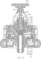
- Fig. 9 and 10 show an embodiment of a multi-way valve with an electric drive. Although only manual or electrical actuation of the multi-way valve will be described in this specification, the present invention is not limited to such operations, but actuation may also be pneumatic or hydraulic.
- Fig. 9 shows a perspective 3D view of an electrically operated multi-way valve and the Fig. 10 shows a section along the central axis of the multi-way valve.
- the lever in the previous figures is replaced by a motor and gear tower.
- Reference numeral 500 denotes a motor for rotating the actuator (in FIG Fig. 9 not shown) to select a valve member
- numeral 600 designates a motor for lifting the actuator to open a valve member.
- the rotational movement of the motors 500 and 600 are transmitted via gears 510 and 610, on the switching shaft and the actuator.
- Fig. 10 shows in the upper region of the actuator 100 has an internal thread 622, into which an external thread 621 of a drive shaft 620 can engage. Turns a motor (in Fig. 10 not shown) via the gear 610, the drive shaft 620, the actuator 100 is raised. Via the gear 510, a motor (in Fig. 10 not shown) rotate the actuator to select a valve element.
- the actuator 100 may be provided with a left-hand thread 622 at the top.
- the drive shaft 620 then receives the corresponding mating thread 621.
- Between actuator 100 and drive shaft 620 may be a freewheel.
- the actuator 100 When the drive shaft 620 rotates to the right, the actuator 100 may be radially positioned, for example, by means of a potentiometer.
- the freewheel stops rotating motion.
- the thread of the drive now acts as a spindle drive, which raises or lowers the actuator 100.
- the freewheel engages again and the actuator 100 can be repositioned.
- the drive can also be mounted to save space on the back of the multi-way valve.
Landscapes
- Engineering & Computer Science (AREA)
- General Engineering & Computer Science (AREA)
- Mechanical Engineering (AREA)
- Mechanically-Actuated Valves (AREA)
Claims (13)
- Vanne multivoies (10) en particulier pour des pulvérisateurs agricoles, qui comprend ce qui suit:- un raccord d'alimentation (30);- N raccords de consommateurs (20);- N éléments de vanne (42), qui peuvent respectivement établir une liaison perméable au fluide entre le raccord d'alimentation (30) et au moins un des N raccords de consommateurs (20); et- un organe de réglage (100) pour sélectionner au moins un des N éléments de vanne (42) et pour actionner l'élément de vanne sélectionné (42) dans une position ouverte ou une position fermée;dans laquelle l'organe de réglage (100) et les N éléments de vanne (42) sont configurés et disposés de telle manière que la sélection et l'actionnement d'un des N éléments de vanne (42) puissent se faire de façon indépendante en deux étapes, de telle manière que pendant la sélection dudit au moins un élément de vanne (42) aucun des N éléments de vanne (42) ne soit actionné, dans lequel l'organe de réglage (100) présente une saillie (100a) s'étendant radialement vers l'extérieur par rapport à un axe central (A); et dans lequel chacun des N éléments de vanne (42) présente une découpe (46), dans laquelle la saillie (46) de l'organe de réglage (100) peut s'engager, caractérisée en ce que la saillie (100a) de l'organe de réglage (100) s'étend sur une région radiale, qui permet au choix l'actionnement d'un seul élément de vanne (42) ou l'actionnement simultané de deux éléments de vanne voisins (42).
- Vanne multivoies (10) selon la revendication 1, dans laquelle les N éléments de vanne (42) sont disposés en forme de cercle autour de l'axe central (A) dans des cavités correspondantes d'un corps de vanne multivoies (50), de telle manière que les N éléments vanne (42) soient mobiles indépendamment l'un de l'autre parallèlement à l'axe central (A) à l'intérieur de la cavité correspondante entre une position ouverte et une position fermée.
- Vanne multivoies (10) selon la revendication 2, dans laquelle l'organe de réglage (100) est monté de façon rotative autour de l'axe central (A) et déplaçable parallèlement à l'axe central (A).
- Vanne multivoies (10) selon l'une quelconque des revendications 1 à 3, qui comprend en outre ce qui suit:- un arbre de commutation (120) disposé de façon coaxiale à l'axe central (A) et monté de façon rotative par rapport au corps de vanne multivoies (50), dans lequel l'organe de réglage (100) est relié à l'arbre de commutation (120) d'une façon calée en rotation par rapport à l'arbre de commutation (120) mais mobile parallèlement à l'arbre central (A), de telle manière que l'organe de réglage (100) puisse être mis en rotation par l'arbre de commutation (120) autour de l'axe central (A), afin de sélectionner au moins un des N éléments de vanne (42); et- un dispositif de déplacement pour déplacer l'organe de réglage (100) parallèlement à l'axe central (A) par rapport à l'arbre de commutation (120), de telle manière que l'organe de réglage (100) puisse être déplacé par le dispositif de déplacement par rapport à l'arbre de commutation (120), le long de l'axe central (A) entre une première position correspondant à une vanne fermée et une deuxième position correspondant à une vanne ouverte, afin d'ouvrir ou de fermer ledit au moins un élément de vanne sélectionné (42).
- Vanne multivoies (10) selon la revendication 4, dans laquelle l'organe de réglage (100) est disposé de façon coaxiale autour de l'arbre de commutation (120).
- Vanne multivoies (10) selon une des revendications 4 ou 5, dans laquelle l'organe de réglage (100) et les N éléments de vanne (42) sont configurés et disposés de telle manière que l'arbre de commutation (120) ne puisse être mis en rotation que lorsque l'organe de réglage (100) se trouve dans la première position.
- Vanne multivoies (10) selon l'une quelconque des revendications 1 à 6, dans laquelle la vanne multivoies (10) est configurée de telle manière que tous les N éléments de vanne (42) se trouvent dans la position fermée, lorsque le raccord d'alimentation (30) se trouve sous pression.
- Vanne multivoies (10) selon l'une quelconque des revendications 1 à 7, qui comprend en outre au moins un élément de précontrainte (45), qui maintient au moins un des N éléments de vanne (42) dans une position fermée, aussi longtemps qu'il n'est pas actionné par l'organe de réglage (100).
- Vanne multivoies (10) selon l'une quelconque des revendications 1 à 8, qui présente en outre un dispositif pour sélectionner un élément de vanne (42) et pour actionner l'élément de vanne sélectionné (42).
- Vanne multivoies (10) selon la revendication 9, dans laquelle le dispositif de sélection et d'actionnement est un levier actionnable manuellement (60), qui est fixé par une tige (160) à un élément d'entraînement (160) à l'extrémité de l'arbre de commutation (120), de telle manière que le levier (60) puisse tourner perpendiculairement à l'axe central (A) et soit calé en rotation par rapport à l'arbre de commutation (120) parallèlement à l'axe central (A), dans laquelle le levier (60) est en outre fixé par une tige cylindrique (150) à une extrémité de l'organe de réglage (100), de telle manière que l'organe de réglage (100) puisse être déplacé par rapport à l'arbre de commutation (120) avec le levier (60).
- Vanne multivoies (10) selon la revendication 10, qui présente en outre deux rangées superposées avec N encoches ou en option 2 x N encoches sur un côté extérieur d'une partie cylindrique de l'organe de réglage (100), de telle manière que l'organe de réglage (100) à une position de vanne sélectionnée ou en option en plus à une position intermédiaire puisse s'encliqueter dans une position ouverte ou dans une position fermée.
- Vanne multivoies (10) selon l'une quelconque des revendications 4 à 11, qui présente en outre un anneau d'étanchéité (195) entre l'arbre de commutation (120) et l'organe de réglage (100), ainsi qu'un joint à gorge (170) entre l'organe de réglage (100) et le corps (50) pour l'étanchéité du corps (50).
- Vanne multivoies (10) selon la revendication 9, dans laquelle le dispositif de sélection est un premier moteur (500) avec un premier mécanisme de transmission (510, 520) et le dispositif d'actionnement est un deuxième moteur (600) avec un deuxième mécanisme de transmission (610, 620, 621)
Applications Claiming Priority (1)
| Application Number | Priority Date | Filing Date | Title |
|---|---|---|---|
| DE102014108472.1A DE102014108472A1 (de) | 2014-06-17 | 2014-06-17 | Mehrwegeventil mit zweistufiger Betätigung |
Publications (2)
| Publication Number | Publication Date |
|---|---|
| EP2957802A1 EP2957802A1 (fr) | 2015-12-23 |
| EP2957802B1 true EP2957802B1 (fr) | 2017-09-13 |
Family
ID=53716419
Family Applications (1)
| Application Number | Title | Priority Date | Filing Date |
|---|---|---|---|
| EP15401048.2A Active EP2957802B1 (fr) | 2014-06-17 | 2015-06-01 | Vanne multi-voies a actionnement en deux etapes |
Country Status (3)
| Country | Link |
|---|---|
| EP (1) | EP2957802B1 (fr) |
| DE (1) | DE102014108472A1 (fr) |
| DK (1) | DK2957802T3 (fr) |
Families Citing this family (1)
| Publication number | Priority date | Publication date | Assignee | Title |
|---|---|---|---|---|
| CN112324949B (zh) * | 2020-11-10 | 2022-09-23 | 中核嘉华设备制造股份公司 | 一种哈氏合金旋塞阀及其使用方法 |
Family Cites Families (4)
| Publication number | Priority date | Publication date | Assignee | Title |
|---|---|---|---|---|
| NL59688C (fr) * | ||||
| DE1045749B (de) * | 1955-08-19 | 1958-12-04 | Amp Inc | Vorrichtung zum Steuern von Fluessigkeiten mit mehreren Anschluessen und einem einzigen Handgriff |
| DE102006006985A1 (de) | 2006-02-15 | 2007-08-23 | Amazonen-Werke H. Dreyer Gmbh & Co. Kg | Mehrwegeventil |
| DE102007007870A1 (de) | 2007-02-14 | 2008-08-21 | Amazonen-Werke H. Dreyer Gmbh & Co. Kg | Mehrwegeventil |
-
2014
- 2014-06-17 DE DE102014108472.1A patent/DE102014108472A1/de not_active Withdrawn
-
2015
- 2015-06-01 EP EP15401048.2A patent/EP2957802B1/fr active Active
- 2015-06-01 DK DK15401048.2T patent/DK2957802T3/en active
Non-Patent Citations (1)
| Title |
|---|
| None * |
Also Published As
| Publication number | Publication date |
|---|---|
| EP2957802A1 (fr) | 2015-12-23 |
| DK2957802T3 (en) | 2017-12-11 |
| DE102014108472A1 (de) | 2015-12-17 |
Similar Documents
| Publication | Publication Date | Title |
|---|---|---|
| EP2585687B1 (fr) | Arbres à cames pouvant être déphasé | |
| DE112022003926T5 (de) | Mehrwegeventil | |
| DE102004056867A1 (de) | Düsenvorrichtung | |
| EP2479465B1 (fr) | Dispositif de soupape doté d'un dispositif d'actionnement auxiliaire manuel | |
| WO2016155976A1 (fr) | Soupape à dépression | |
| EP2141113A1 (fr) | Dispositif de réglage destiné à positionner une charge | |
| EP3447346B1 (fr) | Soupape, en particulier servosoupape | |
| AT507158B1 (de) | Stelleinrichtung zum positionieren einer last | |
| EP2957802B1 (fr) | Vanne multi-voies a actionnement en deux etapes | |
| DE2056066A1 (de) | Abschaltventilvorrichtung bei einer Servolenkung für Fahrzeuge | |
| EP2047156B1 (fr) | Dispositif de soupape à système de commande auxiliaire manuel | |
| DE10305590B4 (de) | Elektromagnetische Federdruckbremse | |
| DE102011118240B4 (de) | Mechanischer Lösemechanismus | |
| EP2159358B1 (fr) | Verrou pour un composant destiné à la fermeture d'une ouverture | |
| EP0271661B1 (fr) | Dispositif pour transmettre une force de commande entre deux pièces de construction | |
| EP2966281B1 (fr) | Dispositif de couplage | |
| EP3927997B1 (fr) | Entraînement à vis à billes avec dispositif d'antirotation | |
| EP2818619B1 (fr) | Dispositif de régulation de la séquence de fermeture d'une installation de porte rotative à deux battants | |
| DE102016208788A1 (de) | Betätigungsvorrichtung für ein Getriebe | |
| DE19715239C2 (de) | Elektrischer Ventilstellantrieb | |
| EP1310388B1 (fr) | Soupape de régulation de niveau pour maintenir constante automatiquement la hauteur d'un véhicule utilitaire à suspension pneumatique | |
| WO2025219333A1 (fr) | Entraînement de soupape pour soupape à double siège et soupape à double siège | |
| DE19912906B4 (de) | Hydraulischer Stellantrieb | |
| DE19828465C2 (de) | Schwenkantrieb für Armaturen | |
| DE10259471C1 (de) | Antriebsvorrichtung für eine Armatur |
Legal Events
| Date | Code | Title | Description |
|---|---|---|---|
| PUAI | Public reference made under article 153(3) epc to a published international application that has entered the european phase |
Free format text: ORIGINAL CODE: 0009012 |
|
| AK | Designated contracting states |
Kind code of ref document: A1 Designated state(s): AL AT BE BG CH CY CZ DE DK EE ES FI FR GB GR HR HU IE IS IT LI LT LU LV MC MK MT NL NO PL PT RO RS SE SI SK SM TR |
|
| AX | Request for extension of the european patent |
Extension state: BA ME |
|
| 17P | Request for examination filed |
Effective date: 20160524 |
|
| RBV | Designated contracting states (corrected) |
Designated state(s): AL AT BE BG CH CY CZ DE DK EE ES FI FR GB GR HR HU IE IS IT LI LT LU LV MC MK MT NL NO PL PT RO RS SE SI SK SM TR |
|
| GRAP | Despatch of communication of intention to grant a patent |
Free format text: ORIGINAL CODE: EPIDOSNIGR1 |
|
| INTG | Intention to grant announced |
Effective date: 20170613 |
|
| GRAS | Grant fee paid |
Free format text: ORIGINAL CODE: EPIDOSNIGR3 |
|
| GRAA | (expected) grant |
Free format text: ORIGINAL CODE: 0009210 |
|
| AK | Designated contracting states |
Kind code of ref document: B1 Designated state(s): AL AT BE BG CH CY CZ DE DK EE ES FI FR GB GR HR HU IE IS IT LI LT LU LV MC MK MT NL NO PL PT RO RS SE SI SK SM TR |
|
| REG | Reference to a national code |
Ref country code: GB Ref legal event code: FG4D Free format text: NOT ENGLISH |
|
| REG | Reference to a national code |
Ref country code: CH Ref legal event code: EP |
|
| REG | Reference to a national code |
Ref country code: IE Ref legal event code: FG4D Free format text: LANGUAGE OF EP DOCUMENT: GERMAN |
|
| REG | Reference to a national code |
Ref country code: AT Ref legal event code: REF Ref document number: 928499 Country of ref document: AT Kind code of ref document: T Effective date: 20171015 |
|
| REG | Reference to a national code |
Ref country code: DE Ref legal event code: R096 Ref document number: 502015001894 Country of ref document: DE |
|
| REG | Reference to a national code |
Ref country code: DK Ref legal event code: T3 Effective date: 20171206 |
|
| REG | Reference to a national code |
Ref country code: NL Ref legal event code: FP |
|
| REG | Reference to a national code |
Ref country code: LT Ref legal event code: MG4D |
|
| PG25 | Lapsed in a contracting state [announced via postgrant information from national office to epo] |
Ref country code: HR Free format text: LAPSE BECAUSE OF FAILURE TO SUBMIT A TRANSLATION OF THE DESCRIPTION OR TO PAY THE FEE WITHIN THE PRESCRIBED TIME-LIMIT Effective date: 20170913 Ref country code: FI Free format text: LAPSE BECAUSE OF FAILURE TO SUBMIT A TRANSLATION OF THE DESCRIPTION OR TO PAY THE FEE WITHIN THE PRESCRIBED TIME-LIMIT Effective date: 20170913 Ref country code: SE Free format text: LAPSE BECAUSE OF FAILURE TO SUBMIT A TRANSLATION OF THE DESCRIPTION OR TO PAY THE FEE WITHIN THE PRESCRIBED TIME-LIMIT Effective date: 20170913 Ref country code: LT Free format text: LAPSE BECAUSE OF FAILURE TO SUBMIT A TRANSLATION OF THE DESCRIPTION OR TO PAY THE FEE WITHIN THE PRESCRIBED TIME-LIMIT Effective date: 20170913 Ref country code: NO Free format text: LAPSE BECAUSE OF FAILURE TO SUBMIT A TRANSLATION OF THE DESCRIPTION OR TO PAY THE FEE WITHIN THE PRESCRIBED TIME-LIMIT Effective date: 20171213 |
|
| PG25 | Lapsed in a contracting state [announced via postgrant information from national office to epo] |
Ref country code: BG Free format text: LAPSE BECAUSE OF FAILURE TO SUBMIT A TRANSLATION OF THE DESCRIPTION OR TO PAY THE FEE WITHIN THE PRESCRIBED TIME-LIMIT Effective date: 20171213 Ref country code: ES Free format text: LAPSE BECAUSE OF FAILURE TO SUBMIT A TRANSLATION OF THE DESCRIPTION OR TO PAY THE FEE WITHIN THE PRESCRIBED TIME-LIMIT Effective date: 20170913 Ref country code: GR Free format text: LAPSE BECAUSE OF FAILURE TO SUBMIT A TRANSLATION OF THE DESCRIPTION OR TO PAY THE FEE WITHIN THE PRESCRIBED TIME-LIMIT Effective date: 20171214 Ref country code: RS Free format text: LAPSE BECAUSE OF FAILURE TO SUBMIT A TRANSLATION OF THE DESCRIPTION OR TO PAY THE FEE WITHIN THE PRESCRIBED TIME-LIMIT Effective date: 20170913 Ref country code: LV Free format text: LAPSE BECAUSE OF FAILURE TO SUBMIT A TRANSLATION OF THE DESCRIPTION OR TO PAY THE FEE WITHIN THE PRESCRIBED TIME-LIMIT Effective date: 20170913 |
|
| REG | Reference to a national code |
Ref country code: FR Ref legal event code: PLFP Year of fee payment: 4 |
|
| PG25 | Lapsed in a contracting state [announced via postgrant information from national office to epo] |
Ref country code: CZ Free format text: LAPSE BECAUSE OF FAILURE TO SUBMIT A TRANSLATION OF THE DESCRIPTION OR TO PAY THE FEE WITHIN THE PRESCRIBED TIME-LIMIT Effective date: 20170913 Ref country code: RO Free format text: LAPSE BECAUSE OF FAILURE TO SUBMIT A TRANSLATION OF THE DESCRIPTION OR TO PAY THE FEE WITHIN THE PRESCRIBED TIME-LIMIT Effective date: 20170913 Ref country code: PL Free format text: LAPSE BECAUSE OF FAILURE TO SUBMIT A TRANSLATION OF THE DESCRIPTION OR TO PAY THE FEE WITHIN THE PRESCRIBED TIME-LIMIT Effective date: 20170913 |
|
| PG25 | Lapsed in a contracting state [announced via postgrant information from national office to epo] |
Ref country code: IS Free format text: LAPSE BECAUSE OF FAILURE TO SUBMIT A TRANSLATION OF THE DESCRIPTION OR TO PAY THE FEE WITHIN THE PRESCRIBED TIME-LIMIT Effective date: 20180113 Ref country code: SM Free format text: LAPSE BECAUSE OF FAILURE TO SUBMIT A TRANSLATION OF THE DESCRIPTION OR TO PAY THE FEE WITHIN THE PRESCRIBED TIME-LIMIT Effective date: 20170913 Ref country code: EE Free format text: LAPSE BECAUSE OF FAILURE TO SUBMIT A TRANSLATION OF THE DESCRIPTION OR TO PAY THE FEE WITHIN THE PRESCRIBED TIME-LIMIT Effective date: 20170913 Ref country code: SK Free format text: LAPSE BECAUSE OF FAILURE TO SUBMIT A TRANSLATION OF THE DESCRIPTION OR TO PAY THE FEE WITHIN THE PRESCRIBED TIME-LIMIT Effective date: 20170913 |
|
| REG | Reference to a national code |
Ref country code: DE Ref legal event code: R097 Ref document number: 502015001894 Country of ref document: DE |
|
| PLBE | No opposition filed within time limit |
Free format text: ORIGINAL CODE: 0009261 |
|
| STAA | Information on the status of an ep patent application or granted ep patent |
Free format text: STATUS: NO OPPOSITION FILED WITHIN TIME LIMIT |
|
| 26N | No opposition filed |
Effective date: 20180614 |
|
| PG25 | Lapsed in a contracting state [announced via postgrant information from national office to epo] |
Ref country code: MT Free format text: LAPSE BECAUSE OF FAILURE TO SUBMIT A TRANSLATION OF THE DESCRIPTION OR TO PAY THE FEE WITHIN THE PRESCRIBED TIME-LIMIT Effective date: 20170913 |
|
| PG25 | Lapsed in a contracting state [announced via postgrant information from national office to epo] |
Ref country code: SI Free format text: LAPSE BECAUSE OF FAILURE TO SUBMIT A TRANSLATION OF THE DESCRIPTION OR TO PAY THE FEE WITHIN THE PRESCRIBED TIME-LIMIT Effective date: 20170913 |
|
| REG | Reference to a national code |
Ref country code: CH Ref legal event code: PL |
|
| REG | Reference to a national code |
Ref country code: BE Ref legal event code: MM Effective date: 20180630 |
|
| REG | Reference to a national code |
Ref country code: IE Ref legal event code: MM4A |
|
| PG25 | Lapsed in a contracting state [announced via postgrant information from national office to epo] |
Ref country code: LU Free format text: LAPSE BECAUSE OF NON-PAYMENT OF DUE FEES Effective date: 20180601 Ref country code: MC Free format text: LAPSE BECAUSE OF FAILURE TO SUBMIT A TRANSLATION OF THE DESCRIPTION OR TO PAY THE FEE WITHIN THE PRESCRIBED TIME-LIMIT Effective date: 20170913 |
|
| PG25 | Lapsed in a contracting state [announced via postgrant information from national office to epo] |
Ref country code: CH Free format text: LAPSE BECAUSE OF NON-PAYMENT OF DUE FEES Effective date: 20180630 Ref country code: LI Free format text: LAPSE BECAUSE OF NON-PAYMENT OF DUE FEES Effective date: 20180630 Ref country code: IE Free format text: LAPSE BECAUSE OF NON-PAYMENT OF DUE FEES Effective date: 20180601 |
|
| PG25 | Lapsed in a contracting state [announced via postgrant information from national office to epo] |
Ref country code: BE Free format text: LAPSE BECAUSE OF NON-PAYMENT OF DUE FEES Effective date: 20180630 |
|
| GBPC | Gb: european patent ceased through non-payment of renewal fee |
Effective date: 20190601 |
|
| PG25 | Lapsed in a contracting state [announced via postgrant information from national office to epo] |
Ref country code: TR Free format text: LAPSE BECAUSE OF FAILURE TO SUBMIT A TRANSLATION OF THE DESCRIPTION OR TO PAY THE FEE WITHIN THE PRESCRIBED TIME-LIMIT Effective date: 20170913 |
|
| PG25 | Lapsed in a contracting state [announced via postgrant information from national office to epo] |
Ref country code: GB Free format text: LAPSE BECAUSE OF NON-PAYMENT OF DUE FEES Effective date: 20190601 |
|
| PG25 | Lapsed in a contracting state [announced via postgrant information from national office to epo] |
Ref country code: PT Free format text: LAPSE BECAUSE OF FAILURE TO SUBMIT A TRANSLATION OF THE DESCRIPTION OR TO PAY THE FEE WITHIN THE PRESCRIBED TIME-LIMIT Effective date: 20170913 |
|
| PG25 | Lapsed in a contracting state [announced via postgrant information from national office to epo] |
Ref country code: CY Free format text: LAPSE BECAUSE OF FAILURE TO SUBMIT A TRANSLATION OF THE DESCRIPTION OR TO PAY THE FEE WITHIN THE PRESCRIBED TIME-LIMIT Effective date: 20170913 Ref country code: HU Free format text: LAPSE BECAUSE OF FAILURE TO SUBMIT A TRANSLATION OF THE DESCRIPTION OR TO PAY THE FEE WITHIN THE PRESCRIBED TIME-LIMIT; INVALID AB INITIO Effective date: 20150601 Ref country code: MK Free format text: LAPSE BECAUSE OF NON-PAYMENT OF DUE FEES Effective date: 20170913 |
|
| PG25 | Lapsed in a contracting state [announced via postgrant information from national office to epo] |
Ref country code: AL Free format text: LAPSE BECAUSE OF FAILURE TO SUBMIT A TRANSLATION OF THE DESCRIPTION OR TO PAY THE FEE WITHIN THE PRESCRIBED TIME-LIMIT Effective date: 20170913 |
|
| REG | Reference to a national code |
Ref country code: DE Ref legal event code: R081 Ref document number: 502015001894 Country of ref document: DE Owner name: AMAZONEN-WERKE H. DREYER SE & CO. KG, DE Free format text: FORMER OWNER: AMAZONEN-WERKE H. DREYER GMBH & CO. KG, 49205 HASBERGEN, DE |
|
| REG | Reference to a national code |
Ref country code: AT Ref legal event code: MM01 Ref document number: 928499 Country of ref document: AT Kind code of ref document: T Effective date: 20200601 |
|
| PG25 | Lapsed in a contracting state [announced via postgrant information from national office to epo] |
Ref country code: AT Free format text: LAPSE BECAUSE OF NON-PAYMENT OF DUE FEES Effective date: 20200601 |
|
| REG | Reference to a national code |
Ref country code: FR Ref legal event code: PLFP Year of fee payment: 9 |
|
| P01 | Opt-out of the competence of the unified patent court (upc) registered |
Effective date: 20230523 |
|
| PGFP | Annual fee paid to national office [announced via postgrant information from national office to epo] |
Ref country code: NL Payment date: 20250409 Year of fee payment: 11 |
|
| PGFP | Annual fee paid to national office [announced via postgrant information from national office to epo] |
Ref country code: DE Payment date: 20250402 Year of fee payment: 11 |
|
| PGFP | Annual fee paid to national office [announced via postgrant information from national office to epo] |
Ref country code: DK Payment date: 20250618 Year of fee payment: 11 |
|
| PGFP | Annual fee paid to national office [announced via postgrant information from national office to epo] |
Ref country code: IT Payment date: 20250522 Year of fee payment: 11 |
|
| PGFP | Annual fee paid to national office [announced via postgrant information from national office to epo] |
Ref country code: FR Payment date: 20250401 Year of fee payment: 11 |