EP2957821B1 - Drehbares beleuchtungs- und/oder signalisierungsmodul - Google Patents
Drehbares beleuchtungs- und/oder signalisierungsmodul Download PDFInfo
- Publication number
- EP2957821B1 EP2957821B1 EP15166197.2A EP15166197A EP2957821B1 EP 2957821 B1 EP2957821 B1 EP 2957821B1 EP 15166197 A EP15166197 A EP 15166197A EP 2957821 B1 EP2957821 B1 EP 2957821B1
- Authority
- EP
- European Patent Office
- Prior art keywords
- frame
- optical device
- screen
- additional optical
- screens
- Prior art date
- Legal status (The legal status is an assumption and is not a legal conclusion. Google has not performed a legal analysis and makes no representation as to the accuracy of the status listed.)
- Active
Links
Images

Classifications
-
- F—MECHANICAL ENGINEERING; LIGHTING; HEATING; WEAPONS; BLASTING
- F21—LIGHTING
- F21S—NON-PORTABLE LIGHTING DEVICES; SYSTEMS THEREOF; VEHICLE LIGHTING DEVICES SPECIALLY ADAPTED FOR VEHICLE EXTERIORS
- F21S43/00—Signalling devices specially adapted for vehicle exteriors, e.g. brake lamps, direction indicator lights or reversing lights
-
- F—MECHANICAL ENGINEERING; LIGHTING; HEATING; WEAPONS; BLASTING
- F21—LIGHTING
- F21S—NON-PORTABLE LIGHTING DEVICES; SYSTEMS THEREOF; VEHICLE LIGHTING DEVICES SPECIALLY ADAPTED FOR VEHICLE EXTERIORS
- F21S43/00—Signalling devices specially adapted for vehicle exteriors, e.g. brake lamps, direction indicator lights or reversing lights
- F21S43/20—Signalling devices specially adapted for vehicle exteriors, e.g. brake lamps, direction indicator lights or reversing lights characterised by refractors, transparent cover plates, light guides or filters
- F21S43/235—Light guides
- F21S43/242—Light guides characterised by the emission area
- F21S43/245—Light guides characterised by the emission area emitting light from one or more of its major surfaces
-
- F—MECHANICAL ENGINEERING; LIGHTING; HEATING; WEAPONS; BLASTING
- F21—LIGHTING
- F21S—NON-PORTABLE LIGHTING DEVICES; SYSTEMS THEREOF; VEHICLE LIGHTING DEVICES SPECIALLY ADAPTED FOR VEHICLE EXTERIORS
- F21S41/00—Illuminating devices specially adapted for vehicle exteriors, e.g. headlamps
- F21S41/60—Illuminating devices specially adapted for vehicle exteriors, e.g. headlamps characterised by a variable light distribution
-
- F—MECHANICAL ENGINEERING; LIGHTING; HEATING; WEAPONS; BLASTING
- F21—LIGHTING
- F21S—NON-PORTABLE LIGHTING DEVICES; SYSTEMS THEREOF; VEHICLE LIGHTING DEVICES SPECIALLY ADAPTED FOR VEHICLE EXTERIORS
- F21S41/00—Illuminating devices specially adapted for vehicle exteriors, e.g. headlamps
- F21S41/60—Illuminating devices specially adapted for vehicle exteriors, e.g. headlamps characterised by a variable light distribution
- F21S41/63—Illuminating devices specially adapted for vehicle exteriors, e.g. headlamps characterised by a variable light distribution by acting on refractors, filters or transparent cover plates
- F21S41/635—Illuminating devices specially adapted for vehicle exteriors, e.g. headlamps characterised by a variable light distribution by acting on refractors, filters or transparent cover plates by moving refractors, filters or transparent cover plates
-
- F—MECHANICAL ENGINEERING; LIGHTING; HEATING; WEAPONS; BLASTING
- F21—LIGHTING
- F21S—NON-PORTABLE LIGHTING DEVICES; SYSTEMS THEREOF; VEHICLE LIGHTING DEVICES SPECIALLY ADAPTED FOR VEHICLE EXTERIORS
- F21S41/00—Illuminating devices specially adapted for vehicle exteriors, e.g. headlamps
- F21S41/60—Illuminating devices specially adapted for vehicle exteriors, e.g. headlamps characterised by a variable light distribution
- F21S41/68—Illuminating devices specially adapted for vehicle exteriors, e.g. headlamps characterised by a variable light distribution by acting on screens
- F21S41/683—Illuminating devices specially adapted for vehicle exteriors, e.g. headlamps characterised by a variable light distribution by acting on screens by moving screens
- F21S41/695—Screens rotating around a vertical axis
-
- F—MECHANICAL ENGINEERING; LIGHTING; HEATING; WEAPONS; BLASTING
- F21—LIGHTING
- F21S—NON-PORTABLE LIGHTING DEVICES; SYSTEMS THEREOF; VEHICLE LIGHTING DEVICES SPECIALLY ADAPTED FOR VEHICLE EXTERIORS
- F21S43/00—Signalling devices specially adapted for vehicle exteriors, e.g. brake lamps, direction indicator lights or reversing lights
- F21S43/10—Signalling devices specially adapted for vehicle exteriors, e.g. brake lamps, direction indicator lights or reversing lights characterised by the light source
- F21S43/13—Signalling devices specially adapted for vehicle exteriors, e.g. brake lamps, direction indicator lights or reversing lights characterised by the light source characterised by the type of light source
- F21S43/14—Light emitting diodes [LED]
-
- F—MECHANICAL ENGINEERING; LIGHTING; HEATING; WEAPONS; BLASTING
- F21—LIGHTING
- F21S—NON-PORTABLE LIGHTING DEVICES; SYSTEMS THEREOF; VEHICLE LIGHTING DEVICES SPECIALLY ADAPTED FOR VEHICLE EXTERIORS
- F21S43/00—Signalling devices specially adapted for vehicle exteriors, e.g. brake lamps, direction indicator lights or reversing lights
- F21S43/20—Signalling devices specially adapted for vehicle exteriors, e.g. brake lamps, direction indicator lights or reversing lights characterised by refractors, transparent cover plates, light guides or filters
- F21S43/235—Light guides
- F21S43/236—Light guides characterised by the shape of the light guide
- F21S43/241—Light guides characterised by the shape of the light guide of complex shape
-
- F—MECHANICAL ENGINEERING; LIGHTING; HEATING; WEAPONS; BLASTING
- F21—LIGHTING
- F21V—FUNCTIONAL FEATURES OR DETAILS OF LIGHTING DEVICES OR SYSTEMS THEREOF; STRUCTURAL COMBINATIONS OF LIGHTING DEVICES WITH OTHER ARTICLES, NOT OTHERWISE PROVIDED FOR
- F21V19/00—Fastening of light sources or lamp holders
- F21V19/001—Fastening of light sources or lamp holders the light sources being semiconductors devices, e.g. LEDs
-
- F—MECHANICAL ENGINEERING; LIGHTING; HEATING; WEAPONS; BLASTING
- F21—LIGHTING
- F21V—FUNCTIONAL FEATURES OR DETAILS OF LIGHTING DEVICES OR SYSTEMS THEREOF; STRUCTURAL COMBINATIONS OF LIGHTING DEVICES WITH OTHER ARTICLES, NOT OTHERWISE PROVIDED FOR
- F21V21/00—Supporting, suspending, or attaching arrangements for lighting devices; Hand grips
- F21V21/14—Adjustable mountings
- F21V21/30—Pivoted housings or frames
-
- F—MECHANICAL ENGINEERING; LIGHTING; HEATING; WEAPONS; BLASTING
- F21—LIGHTING
- F21W—INDEXING SCHEME ASSOCIATED WITH SUBCLASSES F21K, F21L, F21S and F21V, RELATING TO USES OR APPLICATIONS OF LIGHTING DEVICES OR SYSTEMS
- F21W2102/00—Exterior vehicle lighting devices for illuminating purposes
-
- F—MECHANICAL ENGINEERING; LIGHTING; HEATING; WEAPONS; BLASTING
- F21—LIGHTING
- F21W—INDEXING SCHEME ASSOCIATED WITH SUBCLASSES F21K, F21L, F21S and F21V, RELATING TO USES OR APPLICATIONS OF LIGHTING DEVICES OR SYSTEMS
- F21W2107/00—Use or application of lighting devices on or in particular types of vehicles
- F21W2107/10—Use or application of lighting devices on or in particular types of vehicles for land vehicles
Definitions
- the invention relates to the field of lighting and / or signaling, especially for motor vehicles. More particularly, the invention relates to a lighting and / or signaling module for a motor vehicle, and a projector comprising such a module.
- the document EP 2902701 A which falls under Article 54 (3) EPC, describes a lighting and / or signaling module, in particular for a motor vehicle, comprising a support of a first face reflecting the light rays emitted by a first fixed light source.
- It further comprises a frame comprising two screens, at least one of which acts as an optical guide, and a base connecting them transversely to one of their end, said frame being rotatably mounted around an axis under the effect of an actuator, so that said two screens are able to take alternately an active position upstream of the support, in particular in the path of the light rays deflected by said optical deflection means, and in which the screen in active position is located at the right of a second light source, also fixed.
- the document FR 2 817 212 describes a motor vehicle headlamp with a directional lighting function better known by the acronym DBL (Dynamic Bending Light).
- the projector includes an optical system whose lighting direction is rotated, an output shaft coupled to the optical system for driving, an engine, and a rotational transmission mechanism coupled to the engine so that it is rotated. transmits the rotation of the motor to the output shaft, wherein the motor, the output shaft and the rotation transmission mechanism are placed in a housing body, and a rotating shaft of the motor is supported by the housing body .
- a support shaft of an intermediate gear placed between the motor and the output shaft is directly supported by the housing body.
- the document EP 1 285812 discloses a projector having a movable assembly provided with a reflector and a light source, and a fixed assembly at least partially bordering the moving assembly which is rotatable relative to the fixed assembly about a first vertical axis for azimuth adjustment, and around a horizontal transverse axis for on-site adjustment. Such an arrangement is intended to keep the running games constant between the fixed parts and the moving parts.
- the document EP 2 423 047 describes a headlamp of a motor vehicle designed to combine the night lighting function with the daylighting function known by the acronym DRL (Daytime Running Light). Night lighting is achieved by a fixed lighting module, while DRL lighting is realized by means of a network of light-emitting diodes which can be retracted into a position inside the projector.
- DRL Daytime Running Light
- the invention aims to provide a module and a lighting projector and / or signaling capable of providing at least two lighting and / or signaling functions and simple and compact construction.
- the subject of the invention is a lighting and / or signaling module, in particular for a motor vehicle, comprising a support for means for optical deflection of light rays emitted by a first fixed light source, in which a chassis comprises two screens and a base connecting them transversely to one of their end, said frame being rotatably mounted about an axis under the effect of an actuator, so that said two screens are able to take alternately a position active upstream of the support, in particular on the path of the light rays deflected by said optical deflection means, and wherein the active position screen is in line with a second light source, also fixed. At least one additional optical device extends between the screens.
- the invention also relates to a lighting and / or signaling projector for a motor vehicle, comprising a housing and at least one lighting and / or signaling module, in which the lighting and / or signaling module conforms to to what has been described previously.
- the projector can advantageously comprise three lighting modules and / or signaling.
- a lighting and / or signaling module 10 is fixed in a housing (not shown) of a projector, and it comprises a support 16 having a reflecting face and an aspect face, as well as a frame 18 which has two light-transparent screens and which is mounted around the support 16 so that each of the screens of the frame can be arranged facing one of the faces of the support.
- This frame may be fixed relative to the module, or may be rotatably mounted, and this in solidarity with rotation of the support or independently of the support, so that the frame can rotate around the support, while that it remains fixed or rotates elsewhere.
- An embodiment will be described below, in which the support is rotatably mounted and the chassis rotates in solidarity with it, but it will be understood that the variants mentioned at the beginning of this paragraph can be easily implemented without depart from the context of the invention.
- the support is rotatably mounted and the module comprises for this purpose a first actuator 12 integral with the housing of the projector in which the module is housed, and a first axis 14 rotated by the first actuator 12 and secured to the support.
- the first actuator 12 comprises an electric motor, driven by control means (not visible on the Figures 1 and 2 ) and able to transmit a command instruction to said engine, and means for transmitting in rotation between the engine and the first axis.
- the first axis 14 supports the support 16 in its lower part, and the first axis 14 is substantially vertical, but it could have another orientation.
- the support 16 of the module 10 comprises optical deflection means on a first reflecting face 20, which act as a reflector capable of providing a lighting function and / or regulatory signaling. This function is fulfilled by the cooperation of the reflector 20 with a first light source 22.
- the first light source 22 is fixed relative to the actuator.
- a lighting and / or signaling function complies with the regulations in force.
- This lighting function and / or regulatory signaling may be a day signaling function, commonly referred to as the DRL (the English acronym “Daytime Running Light”), or a lighting function of crossing, commonly referred to as “code”, or a lighting function commonly referred to as “road”.
- the first reflecting surface 20 thus ensures the formation of a lighting beam and / or regulatory signaling directed towards the front of the vehicle.
- the first light source 22 is a semiconductor source, and preferably of the electroluminescence diode (LED) type, and is substantially aligned with the first axis 14.
- substantially aligned means that the distance between the geometric center of the light-emitting diode 22 and the axis of rotation of the support 16 is not greater than the dimensions of the light-emitting diode 22.
- the latter can be fixed and positioned on a printed circuit board 24, itself fixed in the case (not shown) of the projector.
- the support 16 of the module 10 also comprises a second face 26 opposite to the first face forming the reflector 20 and providing a second function.
- This second function can be either a regulation day signaling function, a crossover and / or regulatory route function, or an aspect function.
- the module 10 may comprise an upper pivot 36 collinear with the first axis 14 via the support 16 to increase the accuracy of the relative positioning of the first light source 22 with respect to the reflector 20.
- the frame 18 is made of a material transparent to light and has two screens 28 and 30 which extend substantially vertically in the module, parallel to each other, and among which at least one plays the role of light guide.
- Each screen has a peripheral edge 38 and an upper edge 40.
- the screens are connected at their upper end by transverse connecting walls 32 which are connected perpendicularly to the lateral ends of the upper edge of the screen forming an upper connecting base with the support, so that the frame is rotated integrally of the support when it is rotated by the actuator.
- the screens preferably take the form of a sheet light guide, with a central portion of the sheet having a curved profile whose curvature substantially follows the direction of rotation of the frame.
- the chassis is thus arranged in the module so that it surrounds the support, with the first screen 28 or the second screen 30 which is adapted according to the position of the chassis to take the active position upstream of the support.
- upstream the position in which the screen is disposed between the support and the front of the vehicle, to which the lighting and / or signaling functions are directed.
- the central portion of the web of each screen may carry decoupling means, including prisms, for the deviation of the rays reflected by the reflector and through the screen.
- the two screens have different optical surfaces, one having for example a neutral surface, able not to hinder the diffusion of the light rays emitted by the first source 22 and deflected by the reflector, while the other may comprise optical devices whose arrangement may form one or more representative patterns, for example of a mark that is to be highlighted during a signaling function.
- Other structural differences may appear, such as the fact that one of the screens of the frame has elements of decoupling of the light on all or part of its surface for the appearance function, while the other screen does not does not present such an aspect to remain neutral.
- a second light source 34 fixed and positioned on a printed circuit board, advantageously also the card carrying the first light source 22.
- the second light source is able to illuminate the screen of the frame which is in the active position upstream of the support. It is expected that the second light source is disposed at a predetermined distance from the first light source so that the screen of the frame, when in the active position upstream of the support, is arranged in line with the second source of light. light and can be illuminated by it.
- the second light source 34 is fixed relative to the first light source 22 and remains fixed while the support and / or chassis rotates. It may consist of one or more semiconductor sources, for example light-emitting diodes (LEDs). In the illustrated embodiments, two light emitting diodes are provided to form the second light source.
- LEDs light-emitting diodes
- the first screen or the second screen of the frame 18 found in this active position upstream of the support is arranged at the right of the second light source 34 so as to ensure a regulatory signaling function if the second source of light is on.
- the input face of the optical guide, made by one or other of the screens, for the light rays emitted by this second light source is formed by the upper edge of the screen while the exit faces are arranged in the peripheral edge.
- a lighting and / or signaling function is thus realized, distinct from that achieved by the reflection of the light rays of the first light source.
- the peripheral portion of the screen may have a prism oriented in such or such way to proceed to return the light from the second source 34 towards the front of the vehicle to perform a signaling function and / or back to participate to the appearance function.
- the second light source 34 can be turned on in addition to the first light source 22 so that the peripheral portion 38 of the first screen 28, facing the reflector, emits light. This makes it possible to use a first screen of the frame 18 in addition to the reflector 20.
- a preferred use of the two light sources is to keep the second source constantly lit and to increase the intensity of the second light source if one wish to perform a signaling function, or to turn on the first light source if it is desired to perform a lighting function.
- This additional optical device 70 here takes the form of an additional optical device 72, integral with the screens, whose input face is disposed in the horizontal continuity of the upper edge 40 of the screens, and whose output face 74 takes place between the two screens.
- the additional guide 72 is adapted to conduct the light emitted by the second light source 34 and penetrating through the input face, from this input face to the output face 74 by successive internal reflections.
- the additional guide is curved.
- a first curvature is such that the projection of the additional guide in the plane perpendicular to the axis of rotation takes the form of a circular arc centered on said axis of rotation.
- This first curvature of the structural elements has a double interest: a first mechanical interest, in that it allows a radial clearance of the structural elements to allow the relative rotation of the support relative to the frame, and a second aesthetic interest in that it allows to register each of the structural elements in the continuity of the screens of the frame, curves also.
- the exit face of the additional guide is inclined relative to the horizontal, so that it is not completely included in the plane of rotation of the frame.
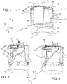
- FIG. 1 discloses a module in which the output face of the additional optical device has a continuous shape, to create a substantially regular rising profile.
- the figure 2 discloses a module in which the output face has, from one edge of a screen to the edge of the other screen, successive successive slopes.
- the figure 3 discloses a module in which the output face of the additional optical device has a stair step shape.
- the module has two additional optical devices.
- a first additional device 70 extends between a first edge of the first screen and a first edge opposite the second screen
- a second additional device 71 extends between a second edge of the first screen and a second edge opposite the second screen.
- second screen This is particularly interesting when the module is rotatable over more than half a turn, since this provides continuity for the observer in front of the vehicle. For a complete turn, the observer can see the following sequence: first screen 28-first additional device 70-second screen 30-second additional device 71-first screen 28.
- the two additional optical devices arranged in the same module are identical and arranged symmetrically with respect to the axis of rotation of the chassis. In this way, when a first additional optical device has an output face which has, for a given direction of rotation of the frame, a rising profile, the second symmetrical additional guide has an exit face which has, for the same direction of rotation, a rising profile also.
- the additional optical device may take other forms than an additional optical device, forming a fairing forming part of the continuity of the screens, since its arrangement and its orientation allow to reflect the light output of the projector with a vertical component modified as the horizontal rotation of the frame is actually made.
- the module is arranged so that when the frame, integrally or not support, is rotatable to move from a position where a first screen is disposed in the active position under the second light source to a position where it is the second screen which is arranged in this active position, it is observed that one or the other additional optical devices, according to the direction of rotation of the frame, passes under the second fixed light source.
- the figure 4 illustrates the module in a configuration where the second screen 28 of the chassis and the aspect face of the support are in the active position, so that the two diodes here forming the second light source 34 can emit rays able to penetrate the screen and to illuminate the exit faces formed by the peripheral portions 38 of the screen.
- FIGS. 5 and 6 illustrate intermediate states between this position of the figure 4 and the position shown on the figure 7 , in which the module has been rotated so that it is the reflective face of the support and the first screen which are in the active position.
- the rays emitted by the second light source impact a part of the output face that is higher and higher.
- the vertical component of the arrangement of the output face of the additional optical device ensures that the point of impact of the light rays emitted by the second source on the output face of the additional optical device as and when required. its passage in front of the second source moves vertically.
- the observer can thus have the impression that the module undergoes both a rotation in the horizontal plane and a vertical translation, similar to a rising helical movement.
- the headlight of a motor vehicle for performing lighting and / or signaling functions, may comprise one or more modules identical to that which has been described, arranged in series in a housing.
- a series of several modules advantageously three, it will be possible to rotate the frame of each module by actuators that can be controlled independently of each other, to provide greater flexibility in the functions of lighting and / or signaling.
Landscapes
- Engineering & Computer Science (AREA)
- General Engineering & Computer Science (AREA)
- Physics & Mathematics (AREA)
- Microelectronics & Electronic Packaging (AREA)
- Optics & Photonics (AREA)
- Non-Portable Lighting Devices Or Systems Thereof (AREA)
- Lighting Device Outwards From Vehicle And Optical Signal (AREA)
Claims (16)
- Beleuchtungs- und/oder Signalisierungsmodul, insbesondere für ein Kraftfahrzeug, das einen Träger (16) für Mittel zur optischen Ablenkung (20) von Lichtstrahlen aufweist, die von einer ersten festen Lichtquelle (22) abgegeben werden,
wobei das Modul ferner ein Gestell (18) aufweist, das zwei Schirme (28, 30), von denen mindestens einer die Rolle eines optischen Leiters übernimmt, sowie eine Basis (32), die sie quer an einem ihres Endes verbindet, aufweist, wobei das Gestell unter der Wirkung eines Betätigungselements drehbar um eine Achse angebracht ist, damit die zwei Schirme geeignet sind, abwechselnd eine aktive Position stromauf des Trägers einzunehmen, insbesondere auf der Bahn der Lichtstrahlen, die von den Mitteln zur optischen Ablenkung abgelenkt werden, und wobei sich der Schirm in aktiver Position gegenüber einer zweiten, ebenfalls festen Lichtquelle (34) befindet, wobei das Modul mindestens eine zusätzliche optische Vorrichtung (70) aufweist, die sich zwischen den Schirmen erstreckt. - Modul nach Anspruch 1, dadurch gekennzeichnet, dass die mindestens eine zusätzliche optische Vorrichtung (70) angeordnet ist, während der Drehung des Gestells (18) gegenüber der zweiten festen Lichtquelle (34) vorbeizulaufen.
- Modul nach Anspruch 2, dadurch gekennzeichnet, dass die mindestens eine zusätzliche optische Vorrichtung (70) vertikal bezogen auf die horizontale Drehebene des Gestells (18) geneigt ist, damit der Reflexionspunkt auf der zusätzlichen optischen Anordnung des Lichts, das von der zweiten Lichtquelle (34) abgegeben wird, während der Drehung des Gestells in der Höhe variiert.
- Modul nach dem vorhergehenden Anspruch, dadurch gekennzeichnet, dass die mindestens eine zusätzliche optische Vorrichtung (70) eine Krümmung in der horizontalen Drehebene des Gestells (18) aufweist, die der Krümmung in derselben Ebene (28, 30) der Schirme im Wesentlichen gleichwertig ist, um sich in der Verlängerung der Schirme zu befinden.
- Modul nach einem der vorhergehenden Ansprüche, dadurch gekennzeichnet, dass die zusätzliche optische Vorrichtung (70) aus einer zusätzlichen optischen Vorrichtung (72) besteht, die zwischen dem Rand eines ersten Schirms (28) des Gestells (18) und dem Rand gegenüber dem zweiten Schirm (30) angeordnet ist.
- Modul nach dem vorhergehenden Anspruch, dadurch gekennzeichnet, dass die zusätzliche optische Vorrichtung (72) eine Eintrittsseite, die im Wesentlichen auf den oberen Rand (40) der Schirme des Gestells ausgerichtet ist und geeignet ist, die Strahlen zu empfangen, die von der zweiten Lichtquelle (34) abgegeben werden, wenn das Gestell gegenüber der zweiten Lichtquelle vorbeiläuft, und eine Austrittsseite (74), die sich zwischen den Rändern der zwei Schirme (28, 30) erstreckt, aufweist, wobei die zusätzliche optische Vorrichtung geeignet ist, die Lichtstrahlen durch aufeinanderfolgende innere Reflexionen von der Eintrittsseite zu der Austrittsseite zu leiten.
- Modul nach Anspruch 6, dadurch gekennzeichnet, dass die Austrittsseite (74) der zusätzlichen optischen Vorrichtung (72) eine durchgehende Form aufweist, die im Wesentlichen regelmäßig ist.
- Modul nach Anspruch 6, dadurch gekennzeichnet, dass die Austrittsseite (74) von einem Rand eines Schirms (28) zum Rand des anderen Schirms (30) aufeinanderfolgende variable Schrägen aufweist.
- Modul nach Anspruch 6, dadurch gekennzeichnet, dass die Austrittsseite (74) der zusätzlichen optischen Vorrichtung (72) eine Treppenstufenform aufweist.
- Modul nach einem der vorhergehenden Ansprüche, dadurch gekennzeichnet, dass es eine zusätzliche optische Vorrichtung (70), die zwischen einem ersten Rand des ersten Schirms (28) und einem ersten Rand gegenüber dem zweiten Schirm (30) angeordnet ist, sowie eine zweite zusätzliche optische Vorrichtung (71), die zwischen einem zweiten Rand des ersten Schirms (28) und einem zweiten Rand gegenüber dem zweiten Schirm (30) angeordnet ist, aufweist.
- Modul nach einem der vorhergehenden Ansprüche, dadurch gekennzeichnet, dass die Mittel zur optischen Ablenkung (20) unter der Wirkung eines Betätigungselements drehbar um eine zweite Achse angebracht sind, während die erste Lichtquelle bezogen auf das Betätigungselement fest bleibt.
- Modul nach dem vorhergehenden Anspruch, dadurch gekennzeichnet, dass das Gestell (18) unabhängig von den Mitteln zur optischen Ablenkung (20) in Drehung versetzt wird.
- Modul nach einem der vorhergehenden Ansprüche, dadurch gekennzeichnet, dass die Schirme (28, 30) des Gestells (18) von einer Flächenführung gebildet sind, deren Randbereich (38) das Licht der zweiten Lichtquelle (34) zurückwirft, um eine Signalfunktion zu erfüllen.
- Modul nach dem vorhergehenden Anspruch, dadurch gekennzeichnet, dass die mindestens eine zusätzliche optische Vorrichtung (70) mit den Schirmen (28, 30) des Gestells (18) am Randbereich (38) der Schirme verbunden ist.
- Beleuchtungs- und/oder Signalisierungsscheinwerfer für ein Kraftfahrzeug, umfassend ein Gehäuse und mindestens ein Beleuchtungs- und/oder Signalisierungsmodul, dadurch gekennzeichnet, dass das Beleuchtungs- und/oder Signalisierungsmodul einem der Ansprüche 1 bis 14 entspricht.
- Scheinwerfer nach dem vorhergehenden Anspruch, dadurch gekennzeichnet, dass er mindestens zwei Beleuchtungs- und/oder Signalisierungsmodule aufweist.
Applications Claiming Priority (1)
| Application Number | Priority Date | Filing Date | Title |
|---|---|---|---|
| FR1455500A FR3022322B1 (fr) | 2014-06-16 | 2014-06-16 | Module d'eclairage et/ou de signalisation rotatif |
Publications (2)
| Publication Number | Publication Date |
|---|---|
| EP2957821A1 EP2957821A1 (de) | 2015-12-23 |
| EP2957821B1 true EP2957821B1 (de) | 2018-06-13 |
Family
ID=51298857
Family Applications (1)
| Application Number | Title | Priority Date | Filing Date |
|---|---|---|---|
| EP15166197.2A Active EP2957821B1 (de) | 2014-06-16 | 2015-05-04 | Drehbares beleuchtungs- und/oder signalisierungsmodul |
Country Status (3)
| Country | Link |
|---|---|
| EP (1) | EP2957821B1 (de) |
| CN (1) | CN105180047B (de) |
| FR (1) | FR3022322B1 (de) |
Families Citing this family (5)
| Publication number | Priority date | Publication date | Assignee | Title |
|---|---|---|---|---|
| FR3050797B1 (fr) * | 2016-04-28 | 2019-11-29 | Valeo Vision | Module lumineux rotatif |
| EP3441261B8 (de) | 2017-08-08 | 2020-04-08 | Marelli Automotive Lighting Italy S.p.A. | Beleuchtungsvorrichtung für fahrzeuge mit rotierenden modulen |
| EP3441665B1 (de) | 2017-08-08 | 2022-05-11 | Marelli Automotive Lighting Italy S.p.A. | Rotierendes beleuchtungsmodul für fahrzeuge und zugehörige beleuchtungsvorrichtung für fahrzeuge |
| WO2019155426A1 (en) * | 2018-02-09 | 2019-08-15 | Gentex Corporation | Adaptive lighting array with image-based control |
| FR3090523B1 (fr) * | 2018-12-19 | 2021-01-01 | Valeo Comfort & Driving Assistance | Dispositif d'éclairage pour plafonnier de véhicule |
Family Cites Families (16)
| Publication number | Priority date | Publication date | Assignee | Title |
|---|---|---|---|---|
| FR2797677B1 (fr) * | 1999-08-19 | 2001-11-23 | Peugeot Citroen Automobiles Sa | Dispositif d'eclairage et/ou de signalisation pour vehicule, et vehicule pourvu d'un tel dispositif |
| JP2002160581A (ja) | 2000-11-24 | 2002-06-04 | Koito Mfg Co Ltd | 車輌用灯具及び回動用駆動装置 |
| FR2828851B1 (fr) | 2001-08-21 | 2003-12-12 | Valeo Vision | Appareil d'eclairage, notamment projecteur, automobile |
| FR2882589B1 (fr) * | 2005-02-28 | 2007-12-28 | Valeo Vision Sa | Dispositif d'eclairage ou de signalisation perfectionne pour vehicule automobile |
| JP2008004512A (ja) * | 2006-06-26 | 2008-01-10 | Ichikoh Ind Ltd | 車両用補助前照ランプ |
| CN101266031B (zh) * | 2008-05-13 | 2011-04-06 | 郭廷麟 | 机动车前照灯 |
| JP5177873B2 (ja) * | 2008-07-11 | 2013-04-10 | 株式会社小糸製作所 | 車両用灯具 |
| FR2940403B1 (fr) * | 2008-12-19 | 2014-01-17 | Valeo Vision Sas | Dispositif d'eclairage pour projecteur de vehicule assurant plusieurs fonctions d'eclairage ou une fonction variable avec une seule source lumineuse |
| DE102009033062A1 (de) * | 2009-07-03 | 2011-01-05 | Volkswagen Ag | Scheinwerfersystem mit Lichtauskoppelfunktion |
| FR2965039B1 (fr) * | 2010-07-26 | 2016-04-15 | Valeo Vision | Module optique de dispositif d'eclairage et/ou de signalisation d'un vehicule automobile |
| FR2964069B1 (fr) | 2010-08-31 | 2013-04-12 | Valeo Vision | Dispositif d'eclairage et/ou de signalisation a element diurne mobile |
| FR2970543A1 (fr) * | 2011-01-14 | 2012-07-20 | Valeo Vision | Dispositif d'eclairage ou de signalisation a guide optique pour vehicule automobile |
| FR2983279B1 (fr) * | 2011-11-24 | 2015-08-21 | Valeo Vision | Element opaque et mobile empechant une focalisation des rayons solaires dans un projecteur |
| JP2013161569A (ja) * | 2012-02-02 | 2013-08-19 | Ichikoh Ind Ltd | 車両用前照灯および車両用前照灯装置 |
| FR2998944B1 (fr) * | 2012-11-30 | 2019-06-28 | Valeo Illuminacion | Dispositif d'eclairage et/ou de signalisation pour vehicule automobile |
| FR3017189B1 (fr) * | 2014-02-04 | 2019-04-26 | Valeo Vision | Module d'eclairage et/ou de signalisation rotatif a source lumineuse fixe |
-
2014
- 2014-06-16 FR FR1455500A patent/FR3022322B1/fr active Active
-
2015
- 2015-05-04 EP EP15166197.2A patent/EP2957821B1/de active Active
- 2015-06-11 CN CN201510319197.XA patent/CN105180047B/zh active Active
Non-Patent Citations (1)
| Title |
|---|
| None * |
Also Published As
| Publication number | Publication date |
|---|---|
| FR3022322A1 (fr) | 2015-12-18 |
| CN105180047A (zh) | 2015-12-23 |
| EP2957821A1 (de) | 2015-12-23 |
| CN105180047B (zh) | 2019-11-12 |
| FR3022322B1 (fr) | 2016-07-15 |
Similar Documents
| Publication | Publication Date | Title |
|---|---|---|
| EP2957822B1 (de) | Drehbares beleuchtungs- und/oder signalisierungsmodul | |
| EP2902701B1 (de) | Drehbares Beleuchtungs- und/oder Signalisierungsmodul mit feststehender Lichtquelle | |
| EP3094919B1 (de) | Beleuchtungsvorrichtung mit beweglicher linse für kraftfahrzeug | |
| EP2957464B1 (de) | Drehbares beleuchtungs- und/oder signalisierungsmodul | |
| EP2957821B1 (de) | Drehbares beleuchtungs- und/oder signalisierungsmodul | |
| EP2799286B1 (de) | Drehbar und multifunktionnale Modul für Signalisierung und/or für Beleuchtung | |
| EP2546569A2 (de) | Multifunktions-Beleuchtungs-/Signalisierungsvorrichtung für Kraftfahrzeug | |
| EP3238991A1 (de) | Drehbares beleuchtungsmodul | |
| EP2957823B1 (de) | Drehbares beleuchtungs- und/oder signalisierungsmodul | |
| EP3152480B1 (de) | Beleuchtungsvorrichtung mit beweglicher linse für kraftfahrzeug | |
| EP2957819A1 (de) | Drehbares beleuchtungs- und/oder signalisierungsmodul | |
| EP3238992B1 (de) | Drehbares leuchtmodul | |
| EP2957820B1 (de) | Drehbares beleuchtungs- und/oder signalisierungsmodul | |
| EP2853804B1 (de) | Beleuchtungs- und/oder signalisierungsmodul mit mehreren drehbaren optischen systemen | |
| FR3022323A1 (fr) | Module d'eclairage et/ou de signalisation rotatif | |
| FR3016569A1 (fr) | Dispositif de signalisation par diffusion pour vehicule automobile | |
| FR3016566A1 (fr) | Dispositif d'eclairage pendulaire pour vehicule automobile | |
| FR3146976A1 (fr) | Dispositif d’éclairage à guide de lumière à prismes de réflexion dispersifs | |
| FR3062706B1 (fr) | Reflecteur multifonction par deplacement | |
| FR3022329A1 (fr) | Module d'eclairage et/ou de signalisation rotatif | |
| WO2020079341A1 (fr) | Module lumineux assurant deux fonctions photométriques présentant des signatures lumineuses distinctes | |
| EP1953039A2 (de) | Multifunktionsbeleuchtungsvorrichtung für Kraftfahrzeug | |
| FR3025862A1 (fr) | Dispositif d'eclairage rotatif a lentille a position relative variable par rapport au reflecteur, pour un bloc optique de vehicule | |
| EP2947379A2 (de) | Elliptisches optisches modul für beleuchtungsvorrichtung eines kraftfahrzeugs |
Legal Events
| Date | Code | Title | Description |
|---|---|---|---|
| PUAI | Public reference made under article 153(3) epc to a published international application that has entered the european phase |
Free format text: ORIGINAL CODE: 0009012 |
|
| AK | Designated contracting states |
Kind code of ref document: A1 Designated state(s): AL AT BE BG CH CY CZ DE DK EE ES FI FR GB GR HR HU IE IS IT LI LT LU LV MC MK MT NL NO PL PT RO RS SE SI SK SM TR |
|
| AX | Request for extension of the european patent |
Extension state: BA ME |
|
| 17P | Request for examination filed |
Effective date: 20160302 |
|
| RBV | Designated contracting states (corrected) |
Designated state(s): AL AT BE BG CH CY CZ DE DK EE ES FI FR GB GR HR HU IE IS IT LI LT LU LV MC MK MT NL NO PL PT RO RS SE SI SK SM TR |
|
| REG | Reference to a national code |
Ref country code: DE Ref legal event code: R079 Ref document number: 602015012133 Country of ref document: DE Free format text: PREVIOUS MAIN CLASS: F21S0008100000 Ipc: F21S0041148000 |
|
| GRAP | Despatch of communication of intention to grant a patent |
Free format text: ORIGINAL CODE: EPIDOSNIGR1 |
|
| STAA | Information on the status of an ep patent application or granted ep patent |
Free format text: STATUS: GRANT OF PATENT IS INTENDED |
|
| INTG | Intention to grant announced |
Effective date: 20180115 |
|
| RIC1 | Information provided on ipc code assigned before grant |
Ipc: F21S 41/148 20180101AFI20180110BHEP Ipc: F21S 41/663 20180101ALI20180110BHEP Ipc: F21S 41/695 20180101ALI20180110BHEP Ipc: F21S 41/683 20180101ALI20180110BHEP |
|
| GRAS | Grant fee paid |
Free format text: ORIGINAL CODE: EPIDOSNIGR3 |
|
| GRAA | (expected) grant |
Free format text: ORIGINAL CODE: 0009210 |
|
| STAA | Information on the status of an ep patent application or granted ep patent |
Free format text: STATUS: THE PATENT HAS BEEN GRANTED |
|
| AK | Designated contracting states |
Kind code of ref document: B1 Designated state(s): AL AT BE BG CH CY CZ DE DK EE ES FI FR GB GR HR HU IE IS IT LI LT LU LV MC MK MT NL NO PL PT RO RS SE SI SK SM TR |
|
| REG | Reference to a national code |
Ref country code: GB Ref legal event code: FG4D Free format text: NOT ENGLISH |
|
| REG | Reference to a national code |
Ref country code: CH Ref legal event code: EP Ref country code: AT Ref legal event code: REF Ref document number: 1008860 Country of ref document: AT Kind code of ref document: T Effective date: 20180615 |
|
| REG | Reference to a national code |
Ref country code: DE Ref legal event code: R096 Ref document number: 602015012133 Country of ref document: DE |
|
| REG | Reference to a national code |
Ref country code: IE Ref legal event code: FG4D Free format text: LANGUAGE OF EP DOCUMENT: FRENCH |
|
| REG | Reference to a national code |
Ref country code: NL Ref legal event code: MP Effective date: 20180613 |
|
| REG | Reference to a national code |
Ref country code: LT Ref legal event code: MG4D |
|
| PG25 | Lapsed in a contracting state [announced via postgrant information from national office to epo] |
Ref country code: FI Free format text: LAPSE BECAUSE OF FAILURE TO SUBMIT A TRANSLATION OF THE DESCRIPTION OR TO PAY THE FEE WITHIN THE PRESCRIBED TIME-LIMIT Effective date: 20180613 Ref country code: NO Free format text: LAPSE BECAUSE OF FAILURE TO SUBMIT A TRANSLATION OF THE DESCRIPTION OR TO PAY THE FEE WITHIN THE PRESCRIBED TIME-LIMIT Effective date: 20180913 Ref country code: CY Free format text: LAPSE BECAUSE OF FAILURE TO SUBMIT A TRANSLATION OF THE DESCRIPTION OR TO PAY THE FEE WITHIN THE PRESCRIBED TIME-LIMIT Effective date: 20180613 Ref country code: BG Free format text: LAPSE BECAUSE OF FAILURE TO SUBMIT A TRANSLATION OF THE DESCRIPTION OR TO PAY THE FEE WITHIN THE PRESCRIBED TIME-LIMIT Effective date: 20180913 Ref country code: ES Free format text: LAPSE BECAUSE OF FAILURE TO SUBMIT A TRANSLATION OF THE DESCRIPTION OR TO PAY THE FEE WITHIN THE PRESCRIBED TIME-LIMIT Effective date: 20180613 Ref country code: SE Free format text: LAPSE BECAUSE OF FAILURE TO SUBMIT A TRANSLATION OF THE DESCRIPTION OR TO PAY THE FEE WITHIN THE PRESCRIBED TIME-LIMIT Effective date: 20180613 Ref country code: LT Free format text: LAPSE BECAUSE OF FAILURE TO SUBMIT A TRANSLATION OF THE DESCRIPTION OR TO PAY THE FEE WITHIN THE PRESCRIBED TIME-LIMIT Effective date: 20180613 |
|
| PG25 | Lapsed in a contracting state [announced via postgrant information from national office to epo] |
Ref country code: LV Free format text: LAPSE BECAUSE OF FAILURE TO SUBMIT A TRANSLATION OF THE DESCRIPTION OR TO PAY THE FEE WITHIN THE PRESCRIBED TIME-LIMIT Effective date: 20180613 Ref country code: RS Free format text: LAPSE BECAUSE OF FAILURE TO SUBMIT A TRANSLATION OF THE DESCRIPTION OR TO PAY THE FEE WITHIN THE PRESCRIBED TIME-LIMIT Effective date: 20180613 Ref country code: GR Free format text: LAPSE BECAUSE OF FAILURE TO SUBMIT A TRANSLATION OF THE DESCRIPTION OR TO PAY THE FEE WITHIN THE PRESCRIBED TIME-LIMIT Effective date: 20180914 Ref country code: HR Free format text: LAPSE BECAUSE OF FAILURE TO SUBMIT A TRANSLATION OF THE DESCRIPTION OR TO PAY THE FEE WITHIN THE PRESCRIBED TIME-LIMIT Effective date: 20180613 |
|
| REG | Reference to a national code |
Ref country code: AT Ref legal event code: MK05 Ref document number: 1008860 Country of ref document: AT Kind code of ref document: T Effective date: 20180613 |
|
| PG25 | Lapsed in a contracting state [announced via postgrant information from national office to epo] |
Ref country code: NL Free format text: LAPSE BECAUSE OF FAILURE TO SUBMIT A TRANSLATION OF THE DESCRIPTION OR TO PAY THE FEE WITHIN THE PRESCRIBED TIME-LIMIT Effective date: 20180613 |
|
| PG25 | Lapsed in a contracting state [announced via postgrant information from national office to epo] |
Ref country code: AT Free format text: LAPSE BECAUSE OF FAILURE TO SUBMIT A TRANSLATION OF THE DESCRIPTION OR TO PAY THE FEE WITHIN THE PRESCRIBED TIME-LIMIT Effective date: 20180613 Ref country code: PL Free format text: LAPSE BECAUSE OF FAILURE TO SUBMIT A TRANSLATION OF THE DESCRIPTION OR TO PAY THE FEE WITHIN THE PRESCRIBED TIME-LIMIT Effective date: 20180613 Ref country code: EE Free format text: LAPSE BECAUSE OF FAILURE TO SUBMIT A TRANSLATION OF THE DESCRIPTION OR TO PAY THE FEE WITHIN THE PRESCRIBED TIME-LIMIT Effective date: 20180613 Ref country code: IS Free format text: LAPSE BECAUSE OF FAILURE TO SUBMIT A TRANSLATION OF THE DESCRIPTION OR TO PAY THE FEE WITHIN THE PRESCRIBED TIME-LIMIT Effective date: 20181013 Ref country code: RO Free format text: LAPSE BECAUSE OF FAILURE TO SUBMIT A TRANSLATION OF THE DESCRIPTION OR TO PAY THE FEE WITHIN THE PRESCRIBED TIME-LIMIT Effective date: 20180613 Ref country code: CZ Free format text: LAPSE BECAUSE OF FAILURE TO SUBMIT A TRANSLATION OF THE DESCRIPTION OR TO PAY THE FEE WITHIN THE PRESCRIBED TIME-LIMIT Effective date: 20180613 Ref country code: SK Free format text: LAPSE BECAUSE OF FAILURE TO SUBMIT A TRANSLATION OF THE DESCRIPTION OR TO PAY THE FEE WITHIN THE PRESCRIBED TIME-LIMIT Effective date: 20180613 |
|
| PG25 | Lapsed in a contracting state [announced via postgrant information from national office to epo] |
Ref country code: SM Free format text: LAPSE BECAUSE OF FAILURE TO SUBMIT A TRANSLATION OF THE DESCRIPTION OR TO PAY THE FEE WITHIN THE PRESCRIBED TIME-LIMIT Effective date: 20180613 Ref country code: IT Free format text: LAPSE BECAUSE OF FAILURE TO SUBMIT A TRANSLATION OF THE DESCRIPTION OR TO PAY THE FEE WITHIN THE PRESCRIBED TIME-LIMIT Effective date: 20180613 |
|
| REG | Reference to a national code |
Ref country code: DE Ref legal event code: R097 Ref document number: 602015012133 Country of ref document: DE |
|
| PLBE | No opposition filed within time limit |
Free format text: ORIGINAL CODE: 0009261 |
|
| STAA | Information on the status of an ep patent application or granted ep patent |
Free format text: STATUS: NO OPPOSITION FILED WITHIN TIME LIMIT |
|
| 26N | No opposition filed |
Effective date: 20190314 |
|
| PG25 | Lapsed in a contracting state [announced via postgrant information from national office to epo] |
Ref country code: SI Free format text: LAPSE BECAUSE OF FAILURE TO SUBMIT A TRANSLATION OF THE DESCRIPTION OR TO PAY THE FEE WITHIN THE PRESCRIBED TIME-LIMIT Effective date: 20180613 Ref country code: DK Free format text: LAPSE BECAUSE OF FAILURE TO SUBMIT A TRANSLATION OF THE DESCRIPTION OR TO PAY THE FEE WITHIN THE PRESCRIBED TIME-LIMIT Effective date: 20180613 |
|
| PG25 | Lapsed in a contracting state [announced via postgrant information from national office to epo] |
Ref country code: AL Free format text: LAPSE BECAUSE OF FAILURE TO SUBMIT A TRANSLATION OF THE DESCRIPTION OR TO PAY THE FEE WITHIN THE PRESCRIBED TIME-LIMIT Effective date: 20180613 |
|
| REG | Reference to a national code |
Ref country code: CH Ref legal event code: PL |
|
| GBPC | Gb: european patent ceased through non-payment of renewal fee |
Effective date: 20190504 |
|
| PG25 | Lapsed in a contracting state [announced via postgrant information from national office to epo] |
Ref country code: LI Free format text: LAPSE BECAUSE OF NON-PAYMENT OF DUE FEES Effective date: 20190531 Ref country code: MC Free format text: LAPSE BECAUSE OF FAILURE TO SUBMIT A TRANSLATION OF THE DESCRIPTION OR TO PAY THE FEE WITHIN THE PRESCRIBED TIME-LIMIT Effective date: 20180613 Ref country code: CH Free format text: LAPSE BECAUSE OF NON-PAYMENT OF DUE FEES Effective date: 20190531 |
|
| REG | Reference to a national code |
Ref country code: BE Ref legal event code: MM Effective date: 20190531 |
|
| PG25 | Lapsed in a contracting state [announced via postgrant information from national office to epo] |
Ref country code: LU Free format text: LAPSE BECAUSE OF NON-PAYMENT OF DUE FEES Effective date: 20190504 |
|
| PG25 | Lapsed in a contracting state [announced via postgrant information from national office to epo] |
Ref country code: TR Free format text: LAPSE BECAUSE OF FAILURE TO SUBMIT A TRANSLATION OF THE DESCRIPTION OR TO PAY THE FEE WITHIN THE PRESCRIBED TIME-LIMIT Effective date: 20180613 |
|
| PG25 | Lapsed in a contracting state [announced via postgrant information from national office to epo] |
Ref country code: IE Free format text: LAPSE BECAUSE OF NON-PAYMENT OF DUE FEES Effective date: 20190504 Ref country code: GB Free format text: LAPSE BECAUSE OF NON-PAYMENT OF DUE FEES Effective date: 20190504 |
|
| PG25 | Lapsed in a contracting state [announced via postgrant information from national office to epo] |
Ref country code: BE Free format text: LAPSE BECAUSE OF NON-PAYMENT OF DUE FEES Effective date: 20190531 |
|
| PG25 | Lapsed in a contracting state [announced via postgrant information from national office to epo] |
Ref country code: PT Free format text: LAPSE BECAUSE OF FAILURE TO SUBMIT A TRANSLATION OF THE DESCRIPTION OR TO PAY THE FEE WITHIN THE PRESCRIBED TIME-LIMIT Effective date: 20181015 |
|
| PG25 | Lapsed in a contracting state [announced via postgrant information from national office to epo] |
Ref country code: MT Free format text: LAPSE BECAUSE OF FAILURE TO SUBMIT A TRANSLATION OF THE DESCRIPTION OR TO PAY THE FEE WITHIN THE PRESCRIBED TIME-LIMIT Effective date: 20180613 Ref country code: HU Free format text: LAPSE BECAUSE OF FAILURE TO SUBMIT A TRANSLATION OF THE DESCRIPTION OR TO PAY THE FEE WITHIN THE PRESCRIBED TIME-LIMIT; INVALID AB INITIO Effective date: 20150504 |
|
| PG25 | Lapsed in a contracting state [announced via postgrant information from national office to epo] |
Ref country code: MK Free format text: LAPSE BECAUSE OF FAILURE TO SUBMIT A TRANSLATION OF THE DESCRIPTION OR TO PAY THE FEE WITHIN THE PRESCRIBED TIME-LIMIT Effective date: 20180613 |
|
| P01 | Opt-out of the competence of the unified patent court (upc) registered |
Effective date: 20230528 |
|
| PGFP | Annual fee paid to national office [announced via postgrant information from national office to epo] |
Ref country code: DE Payment date: 20250513 Year of fee payment: 11 |
|
| PGFP | Annual fee paid to national office [announced via postgrant information from national office to epo] |
Ref country code: FR Payment date: 20250530 Year of fee payment: 11 |