EP2957917A1 - Dispositif de pipetage dote d'un boitier - Google Patents
Dispositif de pipetage dote d'un boitier Download PDFInfo
- Publication number
- EP2957917A1 EP2957917A1 EP15172457.2A EP15172457A EP2957917A1 EP 2957917 A1 EP2957917 A1 EP 2957917A1 EP 15172457 A EP15172457 A EP 15172457A EP 2957917 A1 EP2957917 A1 EP 2957917A1
- Authority
- EP
- European Patent Office
- Prior art keywords
- housing part
- pipetting device
- housing
- pipetting
- side walls
- Prior art date
- Legal status (The legal status is an assumption and is not a legal conclusion. Google has not performed a legal analysis and makes no representation as to the accuracy of the status listed.)
- Granted
Links
Images



Classifications
-
- G—PHYSICS
- G01—MEASURING; TESTING
- G01N—INVESTIGATING OR ANALYSING MATERIALS BY DETERMINING THEIR CHEMICAL OR PHYSICAL PROPERTIES
- G01N35/00—Automatic analysis not limited to methods or materials provided for in any single one of groups G01N1/00 - G01N33/00; Handling materials therefor
- G01N35/10—Devices for transferring samples or any liquids to, in, or from, the analysis apparatus, e.g. suction devices, injection devices
Definitions
- the invention relates to a pipetting device with housing, in particular a pipetting robot accommodated in a housing or a casing.
- Pipetting devices for the automated analysis of biological or medical samples are usually housed in a housing in order to provide a largely closed during processing of sample liquid working space can.
- the housing serves in particular to counteract the evaporation of sample liquid by reducing air flows in the working space. Further, the housings also serve to protect operators during the automatic processing of samples when the at least one pipetting unit is reciprocated at high speed within the working space. Finally, contamination of the pipetting device can also be reduced or prevented by the housing.
- the housing is usually designed so that it is firmly connected to a support structure (frame construction) of the pipetting device.
- the housing is formed by fixing shuttering elements, for example in the form of at least partially transparent flaps or plates, to a support structure ensuring the stability of the pipetting device.
- shuttering elements for example in the form of at least partially transparent flaps or plates
- Examples of such pipetting devices with housings can be found, for example, in Applicants' brochure for their STARLINE products, which was available on the Internet at the time of filing of this application under the following link: http://www.hamiltonrobotics.com/fileadmin/user_upload/products/ startour / MR -0805-03_STAR_LINE_web.pdf
- Such housings which are also part of the supporting structure for the pipetting device, have the disadvantage that access to the pipetting device can be difficult and that the assembly of such a pipetting device together with the housing is very complicated.
- the object of the invention is to provide a pipetting device with housing, in which the mentioned disadvantages can be reduced or prevented.
- the housing is designed with its lower and lower housing part independent of a support structure of the pipetting device.
- the upper housing part can be placed in the manner of a hood on the lower housing part or removed from this.
- the housing is basically constructed so that the upper and the lower housing part have a self-supporting structure, so that the housing is stable even without it incorporated pipetting in itself and thus is freely deployable.
- the pipetting device is mounted on the lower housing part due to the force of gravity. Connections for the mutual stabilization of the pipetting device and the two housing parts are not absolutely necessary.
- the achieved unbundling of the housing and pipetting device constructions enables separate production of the pipetting device and the housing and easy assembly, essentially by placing the pipetting device in the lower housing part and subsequently placing the upper housing part on the lower housing part.
- the lower side walls have end faces which face the upper housing part and which comprise at least one partially inclined lower support section.
- the upper side walls have end faces which face the lower housing part and which comprise at least one partially inclined upper support section.
- each end face which are inclined so that they divide in an imaginary extension along the respective lower or upper side wall at an obtuse angle
- the upper housing part and the lower housing part in the region of their end faces with each other in positive connection can be brought. Due to the inclined arrangement of the end faces, a movement of the upper housing part on the lower housing part can be prevented, in particular along a substantially horizontal and substantially parallel to the side walls direction.
- projections and corresponding recesses may be provided on the upper housing part and the lower housing part so that they engage with each other when the upper housing part is arranged on the lower housing part. This can be achieved in particular by drilling in the lower side walls or their end faces and corresponding pins or pins in the upper side walls or their end faces.
- the arrangement of recesses and projections on the upper and lower end sides can be chosen freely and it is conceivable that both recesses and projections are provided on one end face.
- a cutout can be provided, in which a particularly transparent side wall element connecting the upper and lower side walls, preferably a window element made of plastic or glass, can be received or accommodated.
- a particularly transparent side wall element connecting the upper and lower side walls preferably a window element made of plastic or glass
- a groove into which the side wall element can be received or added may be provided.
- the lower housing part has on its front side at least one lower door element, which is movable between an open position and a closed position, in particular pivotable, wherein preferably the lower door element is at least partially made of a transparent material.
- the upper housing part may have on its front side at least one upper door element, which is movable between an open position and a closed position, in particular pivotable, wherein preferably the upper door element is at least partially made of a transparent material.
- an access to the pipetting device can be provided, which is accommodated in the housing.
- sample containers or so-called racks can be introduced or removed from the pipetting device through an opened lower door element.
- the upper and the lower door element are preferably rotatable about an upper or lower pivot axis, such that the upper door element is pivoted when opening upwards and the lower door element is pivoted downwards when opening.
- a closed working space formed by the housing can be formed, in which the pipetting device is received during operation.
- the housing bottom a plurality of mutually separate recesses may be provided, the respective bottom surface is lower than the support surface for the pipetting device.
- the depressions are designed in such a way that they can accommodate further components serving for the operation of the pipetting device, such as, for example, power supply unit, computer unit, ventilation unit and the like.
- lattice-like or slot-like openings may be provided.
- the lower housing part and the upper housing part are made of a plastic, preferably polyurethane or polyurethane foam. Since the two housing parts are designed shell-like or hood-like, they can be produced in a casting process or foaming in a simple manner.
- the use of a plastic foam has the advantage that a good electrical insulation is achieved and weight can beußsprart.
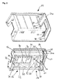
- FIG. 1 is a simplified perspective exploded view of a housing 10 shown in FIG Fig. 7
- the housing 10 comprises an upper housing part 14, which may also be referred to as upper casing or upper half-shell, and a lower casing part 16, which could be referred to as lower casing or lower half-shell.
- the term half-shell is not to be understood as meaning that the upper and the lower housing part respectively surround exactly half of the volume enclosed by them of a jointly formed working space, ie in each case are dimensioned exactly the same.
- the upper housing part 14 comprises a housing roof 18, an upper front side 20, an upper rear side 22, not visible here, and two upper side walls 24a and 24b, which connect the upper front side 20 and the upper rear side 22 to one another.
- the lower housing part 16 comprises a housing bottom 28, a lower front side 30, a lower rear side 32, not visible here, and two lower side walls 34a and 34b which connect the lower front side 30 and the lower rear side 32 to one another.
- an upper door element 26 is attached, which is Drainkbar by means of hinges 27 about an upper pivot axis OS between a closed and an open position.
- a lower door element 36 is mounted, which is pivotable by hinge means 37 about a lower pivot axis US between a closed and an open position.
- the lower door element 36 which is also lower Flap can be designated, shown in its open position, so folded down.
- the upper housing part 14 has in its side walls 24a and 24b respective recesses or cutouts 40a and 40b, wherein in the Fig. 1 only the recess 40a of the right side wall 24a is visible.
- the lower housing part 16 in its side walls 34a and 34b respective recesses or cutouts 42a and 42b.
- a particular transparent side wall member 44a 44b connecting the upper and lower side wall 24a, 34a and 24b, 34b may be used.
- This side wall element 44a, 44b is preferably designed as a window element made of plastic or glass.
- a receiving groove 46a, 46b can be provided along the inner circumference of these recesses, which is in an assembled state with the outer circumference of the respective side wall element 44a, 44b of the housing 10 is engaged.
- the upper housing part 14 can be lowered onto the lower housing part 16 and supported on this.
- the assembly of the two appliance parts 14, 16 is in the other FIGS. 2 to 6 below only for in Fig. 1 right side walls 24a, 34a described, but applies in the same way for the left side walls 24b, 34b.
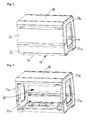
- the upper side wall 24a has an end face 48 facing the lower housing part 16, in particular the lower side wall 34a, which comprises a plurality of support sections 50, 51, 52, 53 ( Fig. 2 ).
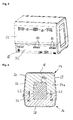
- a plane defined by the housing cover 18 or housing bottom 28 of a composite housing 10 as in Fig. 3 is shown and also in the associated sectional view of the right side in Fig. 6
- the support portions 50 and 53 are inclined to the support portions 51 and 52. Extending the inclined support portions 50, 53 towards the center of the side wall, they intersect at an obtuse angle alpha, which is exemplified in Fig. 3 is shown.
- the support portions 51 and 52 are formed substantially parallel to the plane of the housing cover 18 and the housing bottom 28.
- the lower side wall 34a correspondingly has a lower end face 54, which adjoins the upper housing part 14, and which has a plurality of support sections 55, 56, 57, 58 comprises ( Fig. 2 ).
- FIG. 3 With reference to a plane defined by the housing cover or housing bottom level of a composite housing 10, as shown in FIG Fig. 3 is shown and also in the associated sectional view of the right side in Fig. 6
- the support portions 55 and 58 are inclined to the support portions 56 and 57. Extending the inclined support portions 55, 58 towards the center of the side wall, they intersect at an obtuse angle alpha, which is exemplified in FIG Fig. 3 is shown.
- the bearing portions 56 and 57 are formed substantially parallel to the plane of the housing cover and the housing bottom. If the upper housing part 14 with its bearing portions 50, 51, 52, 53 on the corresponding support portions 55, 56, 57, 58 of the lower housing part 16, a movement of the upper housing part entlag the plane of the side walls (YZ-plane) is restricted or prevented.
- the upper housing part 14 is thus connected in a form-fitting manner to the lower housing part 16 on the two sides of the housing 10.
- two holes 60 are provided in the lower end face 54 by way of example, which can be engaged or engaged with corresponding pin or pin-like connecting elements 62, these connecting elements 62 also being connected to the upper housing part 14 are connected ( Fig. 6 ).
- a recess 64 is visible ( Fig. 2 ), into which a corresponding mandrel 66 can be inserted, which is provided on the lower housing part 16 at the front side 30 thereof.
- a plurality of corresponding recesses and projections may be provided on the upper housing part 14 and on the lower housing part 16, which allow a positive connection between the two housing parts 14, 16 and ensure a safe, in particular non-displaceable resting of the upper housing part 14 on the lower housing part 16 ,
- a plurality of bearing surfaces 70 are provided in the housing bottom, on which a recorded in the lower housing part 16 pipetting device 12 can be supported. Further, a plurality of mutually separate recesses 72 are provided in the housing bottom, the respective bottom surface 74 is lower than the support surfaces 70 for the pipetting 12th
- the housing bottom 28 has a step-like shaped support region 76 in a rear region which adjoins the lower rear side 32. This support region also serves to support the pipetting device 12, which will be described in more detail below.
- the 3 and 4 show a composite housing 10, wherein in Fig. 3 the door elements 26 and 36 are mounted and are shown in their closed position. In Fig. 4 the door elements 26, 36 are omitted, so that the view is free in one of the housing 10, in particular of the two housing parts 14, 16 enclosed volume, which can be referred to as a working space 78.
- the Fig. 5 shows the upper and the lower back 22, 32 of the housing 10.
- slit-like openings 80 are arranged, which serve for ventilation, in particular the dissipation of waste heat.
- a power connection for the pipetting device can be seen.
- Receivable pipetting device 12 is shown in a simplified schematic representation in FIG Fig. 7 shown.
- the pipetting device comprises a receiving plate 84 for receiving at least one (not shown) sample container.
- the pipetting device further comprises a positioning device 86 which comprises a main frame 88 which is movable in a first main direction (X).
- the main frame 88 is mounted in a rear part of the receiving plate 84 on a rail-like structure 90, which is not shown here in detail.
- the main frame 88 In a front region of the receiving plate 84, the main frame 88 is supported on a rod-like carrier 92 rolling.
- a non-illustrated drive means is provided, which the movement along the rail-like construction 90th and the carrier 92.
- the construction of the pipetting device 12 is thus self-supporting, so that operation of the pipetting device is possible regardless of whether the pipetting device is received in the housing 10 and / or connected.
- each pipetting channel 96 Positioned on the positioning device 86 are a plurality of pipetting units 94 with a respective pipetting channel 96 for aspirating and dispensing sample liquid from sample containers, each pipetting channel 96 being movable in the three orthogonal main directions (X, Y, Z) by means of drive units not described in detail herein the movement along the main directions (X, YZ).
- Fig. 8 shows the lower housing part 16 with pipetting device 12 housed therein
- Fig. 9 the upper housing part 14 is placed on the lower housing part 16, so that the pipetting device 12 is received in the working space 78.
- the two door elements 26, 36 are shown in their respective open position. During the performance of sample analyzes, these door elements 26, 36 can be closed. It is also possible to open only the lower door element 36 with the upper door element 26 closed so that the access to the receiving plate 84 is released in order to insert or remove sample containers, for example.
- a recess 98 into which, for example, an external apparatus such as a thermal cycler or the like can be received.
- Fig. 10 From the sectional view of Fig. 10 It can be seen that the pipetting device 12 is supported only on the lower housing part 16, in particular with its receiving plate on the receiving surfaces 70, but also with its rail-like construction 90 on the support portion 76.
- the rod-like support 92 and its two support posts 100 are within the working space 78 freely received and not connected to the housing, in particular the upper housing part 14.
- the upper housing part 14 can therefore be placed independently of the pipetting device 12 on the lower housing part 16 or removed from this.
- the housing 10, in particular its two housing parts 14, 16 are preferably made of a plastic, in particular a foamed plastic. Particularly preferred is the production of the housing 10 made of a polyurethane foam.
- the door members 26, 36 and the side wall members 44a, 44b ( Fig. 1 ) are also made of a plastic, which is preferably transparent.
- a pipetting device 12 with housing 10 the housing 10 and the pipetting device 12 can be manufactured independently of one another, since in particular conventional structural connections between the support structure for the pipetting device and the housing are dispensed with.
- a pipetting device can be accommodated as a pipetting module in a modular housing. Due to the essentially two-part construction of the housing 10 with the upper and lower housing parts 14, 16, maintenance work can also be carried out more easily, and it is also possible to exchange a pipetting device as a whole, without the housing or housing components also having to be exchanged.
Landscapes
- General Health & Medical Sciences (AREA)
- Health & Medical Sciences (AREA)
- Life Sciences & Earth Sciences (AREA)
- Chemical & Material Sciences (AREA)
- Analytical Chemistry (AREA)
- Biochemistry (AREA)
- Physics & Mathematics (AREA)
- General Physics & Mathematics (AREA)
- Immunology (AREA)
- Pathology (AREA)
- Sampling And Sample Adjustment (AREA)
- Apparatus Associated With Microorganisms And Enzymes (AREA)
- Automatic Analysis And Handling Materials Therefor (AREA)
Applications Claiming Priority (1)
| Application Number | Priority Date | Filing Date | Title |
|---|---|---|---|
| DE102014108689.9A DE102014108689A1 (de) | 2014-06-20 | 2014-06-20 | Pipettiervorrichtung mit Gehäuse |
Publications (2)
| Publication Number | Publication Date |
|---|---|
| EP2957917A1 true EP2957917A1 (fr) | 2015-12-23 |
| EP2957917B1 EP2957917B1 (fr) | 2021-04-14 |
Family
ID=53442583
Family Applications (1)
| Application Number | Title | Priority Date | Filing Date |
|---|---|---|---|
| EP15172457.2A Active EP2957917B1 (fr) | 2014-06-20 | 2015-06-17 | Dispositif de pipetage dote d'un boitier |
Country Status (3)
| Country | Link |
|---|---|
| EP (1) | EP2957917B1 (fr) |
| CN (1) | CN105319377B (fr) |
| DE (1) | DE102014108689A1 (fr) |
Cited By (1)
| Publication number | Priority date | Publication date | Assignee | Title |
|---|---|---|---|---|
| WO2021121749A1 (fr) | 2019-12-18 | 2021-06-24 | Hamilton Bonaduz Ag | Système de laboratoire |
Families Citing this family (1)
| Publication number | Priority date | Publication date | Assignee | Title |
|---|---|---|---|---|
| CN106967584A (zh) * | 2017-05-04 | 2017-07-21 | 南昌大学 | 一种自动细胞悬液吹打混匀装置 |
Citations (4)
| Publication number | Priority date | Publication date | Assignee | Title |
|---|---|---|---|---|
| US5627522A (en) * | 1992-03-27 | 1997-05-06 | Abbott Laboratories | Automated liquid level sensing system |
| EP0895088A2 (fr) * | 1997-08-01 | 1999-02-03 | Ortho-Clinical Diagnostics, Inc. | Système automatique d'analyse de sang |
| US20090117004A1 (en) * | 2007-11-06 | 2009-05-07 | Abbott Laboratories | System for automatically loading immunoassay analyzer |
| US20120100047A1 (en) * | 2010-07-23 | 2012-04-26 | Matrix Technologies Corporation | Automated liquid handling device |
Family Cites Families (5)
| Publication number | Priority date | Publication date | Assignee | Title |
|---|---|---|---|---|
| DE10020771A1 (de) * | 2000-04-28 | 2001-10-31 | Merck Patent Gmbh | Pipettiervorrichtung |
| CA2635268C (fr) * | 2006-01-18 | 2021-02-16 | Argos Therapeutics, Inc. | Systemes et procedes destines au traitement d'echantillons dans un receptacle ferme, et dispositifs associes |
| US8703492B2 (en) * | 2007-04-06 | 2014-04-22 | Qiagen Gaithersburg, Inc. | Open platform hybrid manual-automated sample processing system |
| DE102008022835B3 (de) * | 2008-05-12 | 2009-10-22 | Torsten Dr. Matthias | Analysegerät |
| US10022856B2 (en) * | 2010-01-28 | 2018-07-17 | The Stanley Works Israel Ltd. | Metal and plastic container |
-
2014
- 2014-06-20 DE DE102014108689.9A patent/DE102014108689A1/de not_active Withdrawn
-
2015
- 2015-06-17 EP EP15172457.2A patent/EP2957917B1/fr active Active
- 2015-06-23 CN CN201510349383.8A patent/CN105319377B/zh active Active
Patent Citations (4)
| Publication number | Priority date | Publication date | Assignee | Title |
|---|---|---|---|---|
| US5627522A (en) * | 1992-03-27 | 1997-05-06 | Abbott Laboratories | Automated liquid level sensing system |
| EP0895088A2 (fr) * | 1997-08-01 | 1999-02-03 | Ortho-Clinical Diagnostics, Inc. | Système automatique d'analyse de sang |
| US20090117004A1 (en) * | 2007-11-06 | 2009-05-07 | Abbott Laboratories | System for automatically loading immunoassay analyzer |
| US20120100047A1 (en) * | 2010-07-23 | 2012-04-26 | Matrix Technologies Corporation | Automated liquid handling device |
Non-Patent Citations (1)
| Title |
|---|
| G. ALEXANDER GROSS ET AL: "Robotic alliance of miniaturized synthesis and screening: A case study for the identification of histone deacetylase inhibitors", ENGINEERING IN LIFE SCIENCES, vol. 13, no. 4, 28 July 2013 (2013-07-28), pages 344 - 351, XP055217323, ISSN: 1618-0240, DOI: 10.1002/elsc.201200090 * |
Cited By (4)
| Publication number | Priority date | Publication date | Assignee | Title |
|---|---|---|---|---|
| WO2021121749A1 (fr) | 2019-12-18 | 2021-06-24 | Hamilton Bonaduz Ag | Système de laboratoire |
| DE102019134846B4 (de) | 2019-12-18 | 2023-08-17 | Hamilton Bonaduz Ag | Laborsystem |
| DE202020006032U1 (de) | 2019-12-18 | 2024-04-30 | Hamilton Bonaduz Ag | Laborsystem |
| EP4538715A2 (fr) | 2019-12-18 | 2025-04-16 | Hamilton Bonaduz AG | Système de laboratoire |
Also Published As
| Publication number | Publication date |
|---|---|
| CN105319377B (zh) | 2018-01-16 |
| DE102014108689A1 (de) | 2015-12-24 |
| CN105319377A (zh) | 2016-02-10 |
| EP2957917B1 (fr) | 2021-04-14 |
Similar Documents
| Publication | Publication Date | Title |
|---|---|---|
| EP1053581B1 (fr) | Armoire de commande avec dispositif de refroidissement | |
| DE69013232T2 (de) | Tragbares datenverarbeitungsterminal mit schwenkbarer anzeige. | |
| DE2736393A1 (de) | Einstellbares zapfenlager fuer schwenkfenster | |
| DE10302809A1 (de) | Schüttel-Inkubator | |
| DE10057556A1 (de) | Stativkopf, insbesondere für eine medizinische Überwachungs- und Versorgungseinrichtung, Trägerprofil für einen solchen und Gerätewagen | |
| EP2957917B1 (fr) | Dispositif de pipetage dote d'un boitier | |
| DE9203112U1 (de) | Montageelement für Installationskanäle | |
| WO2003069746A1 (fr) | Cadre profile | |
| EP2733290A2 (fr) | Agencement pour une armoire de compteur, une armoire de distribution, une armoire électrique ou un boîtier vide | |
| EP0262427A2 (fr) | Coffret de table pour dispositifs électrotechniques | |
| DE2801852A1 (de) | Installationsmittel fuer die anordnung einer tv-kamera fuer den video-wechselsprechverkehr in einem tableau fuer einen elektrischen tueroeffner | |
| EP2428974B1 (fr) | Sectionneur de sécurité électrique doté d'un couvercle de contacteur mobile | |
| DE102017109437B4 (de) | Gepäckablagenmontagesatz für ein Fahrzeug und Montageverfahren | |
| DE102009055277B4 (de) | Kabelkanal | |
| DE10104215A1 (de) | Verfahren zum Befestigen eines schwenkbaren Elektroschrankmoduls in einem Elektroschrank und Scharnierbausatz | |
| DE202020002391U1 (de) | Spleißmodulstapel mit verbesserter Kabelführung | |
| EP2947241A1 (fr) | Serrure à pêne pour un vantail de porte et procédé de montage | |
| DE19811713A1 (de) | Schaltschrank | |
| DE102018116425A1 (de) | Präsentationsvorrichtung | |
| DE3438206A1 (de) | Anordnung zur waermeableitung bei geraeteeinsaetzen der nachrichtentechnik | |
| DE7816003U1 (de) | Haltevorrichtung für Gewindemuttern | |
| EP1457629A1 (fr) | Dispositif pour la fixation et/ou la connexion rotative d' éléments de porte et/ou de paroi | |
| DE3617108C2 (fr) | ||
| DE102017200304B4 (de) | Isolierbehälter | |
| EP2997862B1 (fr) | Ensemble de boîtes aux lettres avec boîtier en forme de caisson |
Legal Events
| Date | Code | Title | Description |
|---|---|---|---|
| PUAI | Public reference made under article 153(3) epc to a published international application that has entered the european phase |
Free format text: ORIGINAL CODE: 0009012 |
|
| AK | Designated contracting states |
Kind code of ref document: A1 Designated state(s): AL AT BE BG CH CY CZ DE DK EE ES FI FR GB GR HR HU IE IS IT LI LT LU LV MC MK MT NL NO PL PT RO RS SE SI SK SM TR |
|
| AX | Request for extension of the european patent |
Extension state: BA ME |
|
| 17P | Request for examination filed |
Effective date: 20160623 |
|
| RBV | Designated contracting states (corrected) |
Designated state(s): AL AT BE BG CH CY CZ DE DK EE ES FI FR GB GR HR HU IE IS IT LI LT LU LV MC MK MT NL NO PL PT RO RS SE SI SK SM TR |
|
| GRAP | Despatch of communication of intention to grant a patent |
Free format text: ORIGINAL CODE: EPIDOSNIGR1 |
|
| STAA | Information on the status of an ep patent application or granted ep patent |
Free format text: STATUS: GRANT OF PATENT IS INTENDED |
|
| INTG | Intention to grant announced |
Effective date: 20201106 |
|
| GRAS | Grant fee paid |
Free format text: ORIGINAL CODE: EPIDOSNIGR3 |
|
| GRAA | (expected) grant |
Free format text: ORIGINAL CODE: 0009210 |
|
| STAA | Information on the status of an ep patent application or granted ep patent |
Free format text: STATUS: THE PATENT HAS BEEN GRANTED |
|
| AK | Designated contracting states |
Kind code of ref document: B1 Designated state(s): AL AT BE BG CH CY CZ DE DK EE ES FI FR GB GR HR HU IE IS IT LI LT LU LV MC MK MT NL NO PL PT RO RS SE SI SK SM TR |
|
| REG | Reference to a national code |
Ref country code: GB Ref legal event code: FG4D Free format text: NOT ENGLISH |
|
| REG | Reference to a national code |
Ref country code: CH Ref legal event code: EP |
|
| REG | Reference to a national code |
Ref country code: DE Ref legal event code: R096 Ref document number: 502015014544 Country of ref document: DE |
|
| REG | Reference to a national code |
Ref country code: IE Ref legal event code: FG4D Free format text: LANGUAGE OF EP DOCUMENT: GERMAN |
|
| REG | Reference to a national code |
Ref country code: AT Ref legal event code: REF Ref document number: 1382883 Country of ref document: AT Kind code of ref document: T Effective date: 20210515 |
|
| REG | Reference to a national code |
Ref country code: LT Ref legal event code: MG9D |
|
| REG | Reference to a national code |
Ref country code: NL Ref legal event code: MP Effective date: 20210414 |
|
| PG25 | Lapsed in a contracting state [announced via postgrant information from national office to epo] |
Ref country code: HR Free format text: LAPSE BECAUSE OF FAILURE TO SUBMIT A TRANSLATION OF THE DESCRIPTION OR TO PAY THE FEE WITHIN THE PRESCRIBED TIME-LIMIT Effective date: 20210414 Ref country code: FI Free format text: LAPSE BECAUSE OF FAILURE TO SUBMIT A TRANSLATION OF THE DESCRIPTION OR TO PAY THE FEE WITHIN THE PRESCRIBED TIME-LIMIT Effective date: 20210414 Ref country code: NL Free format text: LAPSE BECAUSE OF FAILURE TO SUBMIT A TRANSLATION OF THE DESCRIPTION OR TO PAY THE FEE WITHIN THE PRESCRIBED TIME-LIMIT Effective date: 20210414 Ref country code: LT Free format text: LAPSE BECAUSE OF FAILURE TO SUBMIT A TRANSLATION OF THE DESCRIPTION OR TO PAY THE FEE WITHIN THE PRESCRIBED TIME-LIMIT Effective date: 20210414 Ref country code: BG Free format text: LAPSE BECAUSE OF FAILURE TO SUBMIT A TRANSLATION OF THE DESCRIPTION OR TO PAY THE FEE WITHIN THE PRESCRIBED TIME-LIMIT Effective date: 20210714 |
|
| PG25 | Lapsed in a contracting state [announced via postgrant information from national office to epo] |
Ref country code: GR Free format text: LAPSE BECAUSE OF FAILURE TO SUBMIT A TRANSLATION OF THE DESCRIPTION OR TO PAY THE FEE WITHIN THE PRESCRIBED TIME-LIMIT Effective date: 20210715 Ref country code: LV Free format text: LAPSE BECAUSE OF FAILURE TO SUBMIT A TRANSLATION OF THE DESCRIPTION OR TO PAY THE FEE WITHIN THE PRESCRIBED TIME-LIMIT Effective date: 20210414 Ref country code: IS Free format text: LAPSE BECAUSE OF FAILURE TO SUBMIT A TRANSLATION OF THE DESCRIPTION OR TO PAY THE FEE WITHIN THE PRESCRIBED TIME-LIMIT Effective date: 20210814 Ref country code: NO Free format text: LAPSE BECAUSE OF FAILURE TO SUBMIT A TRANSLATION OF THE DESCRIPTION OR TO PAY THE FEE WITHIN THE PRESCRIBED TIME-LIMIT Effective date: 20210714 Ref country code: PL Free format text: LAPSE BECAUSE OF FAILURE TO SUBMIT A TRANSLATION OF THE DESCRIPTION OR TO PAY THE FEE WITHIN THE PRESCRIBED TIME-LIMIT Effective date: 20210414 Ref country code: PT Free format text: LAPSE BECAUSE OF FAILURE TO SUBMIT A TRANSLATION OF THE DESCRIPTION OR TO PAY THE FEE WITHIN THE PRESCRIBED TIME-LIMIT Effective date: 20210816 Ref country code: ES Free format text: LAPSE BECAUSE OF FAILURE TO SUBMIT A TRANSLATION OF THE DESCRIPTION OR TO PAY THE FEE WITHIN THE PRESCRIBED TIME-LIMIT Effective date: 20210414 Ref country code: SE Free format text: LAPSE BECAUSE OF FAILURE TO SUBMIT A TRANSLATION OF THE DESCRIPTION OR TO PAY THE FEE WITHIN THE PRESCRIBED TIME-LIMIT Effective date: 20210414 Ref country code: RS Free format text: LAPSE BECAUSE OF FAILURE TO SUBMIT A TRANSLATION OF THE DESCRIPTION OR TO PAY THE FEE WITHIN THE PRESCRIBED TIME-LIMIT Effective date: 20210414 |
|
| REG | Reference to a national code |
Ref country code: DE Ref legal event code: R097 Ref document number: 502015014544 Country of ref document: DE |
|
| PG25 | Lapsed in a contracting state [announced via postgrant information from national office to epo] |
Ref country code: SM Free format text: LAPSE BECAUSE OF FAILURE TO SUBMIT A TRANSLATION OF THE DESCRIPTION OR TO PAY THE FEE WITHIN THE PRESCRIBED TIME-LIMIT Effective date: 20210414 Ref country code: SK Free format text: LAPSE BECAUSE OF FAILURE TO SUBMIT A TRANSLATION OF THE DESCRIPTION OR TO PAY THE FEE WITHIN THE PRESCRIBED TIME-LIMIT Effective date: 20210414 Ref country code: CZ Free format text: LAPSE BECAUSE OF FAILURE TO SUBMIT A TRANSLATION OF THE DESCRIPTION OR TO PAY THE FEE WITHIN THE PRESCRIBED TIME-LIMIT Effective date: 20210414 Ref country code: EE Free format text: LAPSE BECAUSE OF FAILURE TO SUBMIT A TRANSLATION OF THE DESCRIPTION OR TO PAY THE FEE WITHIN THE PRESCRIBED TIME-LIMIT Effective date: 20210414 Ref country code: DK Free format text: LAPSE BECAUSE OF FAILURE TO SUBMIT A TRANSLATION OF THE DESCRIPTION OR TO PAY THE FEE WITHIN THE PRESCRIBED TIME-LIMIT Effective date: 20210414 Ref country code: RO Free format text: LAPSE BECAUSE OF FAILURE TO SUBMIT A TRANSLATION OF THE DESCRIPTION OR TO PAY THE FEE WITHIN THE PRESCRIBED TIME-LIMIT Effective date: 20210414 Ref country code: MC Free format text: LAPSE BECAUSE OF FAILURE TO SUBMIT A TRANSLATION OF THE DESCRIPTION OR TO PAY THE FEE WITHIN THE PRESCRIBED TIME-LIMIT Effective date: 20210414 |
|
| PLBE | No opposition filed within time limit |
Free format text: ORIGINAL CODE: 0009261 |
|
| STAA | Information on the status of an ep patent application or granted ep patent |
Free format text: STATUS: NO OPPOSITION FILED WITHIN TIME LIMIT |
|
| REG | Reference to a national code |
Ref country code: BE Ref legal event code: MM Effective date: 20210630 |
|
| 26N | No opposition filed |
Effective date: 20220117 |
|
| GBPC | Gb: european patent ceased through non-payment of renewal fee |
Effective date: 20210714 |
|
| PG25 | Lapsed in a contracting state [announced via postgrant information from national office to epo] |
Ref country code: LU Free format text: LAPSE BECAUSE OF NON-PAYMENT OF DUE FEES Effective date: 20210617 |
|
| PG25 | Lapsed in a contracting state [announced via postgrant information from national office to epo] |
Ref country code: IE Free format text: LAPSE BECAUSE OF NON-PAYMENT OF DUE FEES Effective date: 20210617 Ref country code: GB Free format text: LAPSE BECAUSE OF NON-PAYMENT OF DUE FEES Effective date: 20210714 |
|
| PG25 | Lapsed in a contracting state [announced via postgrant information from national office to epo] |
Ref country code: IS Free format text: LAPSE BECAUSE OF FAILURE TO SUBMIT A TRANSLATION OF THE DESCRIPTION OR TO PAY THE FEE WITHIN THE PRESCRIBED TIME-LIMIT Effective date: 20210814 Ref country code: FR Free format text: LAPSE BECAUSE OF NON-PAYMENT OF DUE FEES Effective date: 20210630 Ref country code: AL Free format text: LAPSE BECAUSE OF FAILURE TO SUBMIT A TRANSLATION OF THE DESCRIPTION OR TO PAY THE FEE WITHIN THE PRESCRIBED TIME-LIMIT Effective date: 20210414 |
|
| PG25 | Lapsed in a contracting state [announced via postgrant information from national office to epo] |
Ref country code: IT Free format text: LAPSE BECAUSE OF FAILURE TO SUBMIT A TRANSLATION OF THE DESCRIPTION OR TO PAY THE FEE WITHIN THE PRESCRIBED TIME-LIMIT Effective date: 20210414 Ref country code: BE Free format text: LAPSE BECAUSE OF NON-PAYMENT OF DUE FEES Effective date: 20210630 |
|
| REG | Reference to a national code |
Ref country code: AT Ref legal event code: MM01 Ref document number: 1382883 Country of ref document: AT Kind code of ref document: T Effective date: 20210617 |
|
| PG25 | Lapsed in a contracting state [announced via postgrant information from national office to epo] |
Ref country code: AT Free format text: LAPSE BECAUSE OF NON-PAYMENT OF DUE FEES Effective date: 20210617 |
|
| PG25 | Lapsed in a contracting state [announced via postgrant information from national office to epo] |
Ref country code: HU Free format text: LAPSE BECAUSE OF FAILURE TO SUBMIT A TRANSLATION OF THE DESCRIPTION OR TO PAY THE FEE WITHIN THE PRESCRIBED TIME-LIMIT; INVALID AB INITIO Effective date: 20150617 |
|
| P01 | Opt-out of the competence of the unified patent court (upc) registered |
Effective date: 20230521 |
|
| PG25 | Lapsed in a contracting state [announced via postgrant information from national office to epo] |
Ref country code: CY Free format text: LAPSE BECAUSE OF FAILURE TO SUBMIT A TRANSLATION OF THE DESCRIPTION OR TO PAY THE FEE WITHIN THE PRESCRIBED TIME-LIMIT Effective date: 20210414 |
|
| PG25 | Lapsed in a contracting state [announced via postgrant information from national office to epo] |
Ref country code: MK Free format text: LAPSE BECAUSE OF FAILURE TO SUBMIT A TRANSLATION OF THE DESCRIPTION OR TO PAY THE FEE WITHIN THE PRESCRIBED TIME-LIMIT Effective date: 20210414 |
|
| PG25 | Lapsed in a contracting state [announced via postgrant information from national office to epo] |
Ref country code: MT Free format text: LAPSE BECAUSE OF FAILURE TO SUBMIT A TRANSLATION OF THE DESCRIPTION OR TO PAY THE FEE WITHIN THE PRESCRIBED TIME-LIMIT Effective date: 20210414 |
|
| PGFP | Annual fee paid to national office [announced via postgrant information from national office to epo] |
Ref country code: DE Payment date: 20250520 Year of fee payment: 11 |
|
| PGFP | Annual fee paid to national office [announced via postgrant information from national office to epo] |
Ref country code: CH Payment date: 20250701 Year of fee payment: 11 |
|
| PG25 | Lapsed in a contracting state [announced via postgrant information from national office to epo] |
Ref country code: TR Free format text: LAPSE BECAUSE OF FAILURE TO SUBMIT A TRANSLATION OF THE DESCRIPTION OR TO PAY THE FEE WITHIN THE PRESCRIBED TIME-LIMIT Effective date: 20210414 |