EP2958035A1 - Simulationssystem, simulationsvorrichtung und verfahren zur unterstützung einer produktbeschreibung - Google Patents
Simulationssystem, simulationsvorrichtung und verfahren zur unterstützung einer produktbeschreibung Download PDFInfo
- Publication number
- EP2958035A1 EP2958035A1 EP13874426.3A EP13874426A EP2958035A1 EP 2958035 A1 EP2958035 A1 EP 2958035A1 EP 13874426 A EP13874426 A EP 13874426A EP 2958035 A1 EP2958035 A1 EP 2958035A1
- Authority
- EP
- European Patent Office
- Prior art keywords
- visual field
- image
- simulation
- spectacle lens
- lens
- Prior art date
- Legal status (The legal status is an assumption and is not a legal conclusion. Google has not performed a legal analysis and makes no representation as to the accuracy of the status listed.)
- Withdrawn
Links
Images


Classifications
-
- G—PHYSICS
- G06—COMPUTING OR CALCULATING; COUNTING
- G06T—IMAGE DATA PROCESSING OR GENERATION, IN GENERAL
- G06T11/00—Two-dimensional [2D] image generation
- G06T11/20—Drawing from basic elements
-
- A—HUMAN NECESSITIES
- A61—MEDICAL OR VETERINARY SCIENCE; HYGIENE
- A61B—DIAGNOSIS; SURGERY; IDENTIFICATION
- A61B3/00—Apparatus for testing the eyes; Instruments for examining the eyes
- A61B3/0016—Operational features thereof
- A61B3/0025—Operational features thereof characterised by electronic signal processing, e.g. eye models
-
- G—PHYSICS
- G02—OPTICS
- G02C—SPECTACLES; SUNGLASSES OR GOGGLES INSOFAR AS THEY HAVE THE SAME FEATURES AS SPECTACLES; CONTACT LENSES
- G02C7/00—Optical parts
- G02C7/02—Lenses; Lens systems ; Methods of designing lenses
- G02C7/024—Methods of designing ophthalmic lenses
- G02C7/028—Special mathematical design techniques
-
- G—PHYSICS
- G06—COMPUTING OR CALCULATING; COUNTING
- G06Q—INFORMATION AND COMMUNICATION TECHNOLOGY [ICT] SPECIALLY ADAPTED FOR ADMINISTRATIVE, COMMERCIAL, FINANCIAL, MANAGERIAL OR SUPERVISORY PURPOSES; SYSTEMS OR METHODS SPECIALLY ADAPTED FOR ADMINISTRATIVE, COMMERCIAL, FINANCIAL, MANAGERIAL OR SUPERVISORY PURPOSES, NOT OTHERWISE PROVIDED FOR
- G06Q30/00—Commerce
- G06Q30/06—Buying, selling or leasing transactions
- G06Q30/0601—Electronic shopping [e-shopping]
- G06Q30/0621—Electronic shopping [e-shopping] by configuring or customising goods or services
-
- G—PHYSICS
- G06—COMPUTING OR CALCULATING; COUNTING
- G06T—IMAGE DATA PROCESSING OR GENERATION, IN GENERAL
- G06T11/00—Two-dimensional [2D] image generation
- G06T11/60—Creating or editing images; Combining images with text
-
- G—PHYSICS
- G06—COMPUTING OR CALCULATING; COUNTING
- G06T—IMAGE DATA PROCESSING OR GENERATION, IN GENERAL
- G06T19/00—Manipulating three-dimensional [3D] models or images for computer graphics
- G06T19/006—Mixed reality
-
- G—PHYSICS
- G06—COMPUTING OR CALCULATING; COUNTING
- G06T—IMAGE DATA PROCESSING OR GENERATION, IN GENERAL
- G06T3/00—Geometric image transformations in the plane of the image
- G06T3/18—Image warping, e.g. rearranging pixels individually
Definitions
- the present invention relates to a simulation system, a simulation device, and a product explanation assistance method for giving a prospective spectacle lens wearer a simulated experience of what it is like to look through a spectacle lens scheduled to be worn.
- Hitherto simulation devices have been employed in a spectacle shop to give a prospective spectacle lens wearer a simulated experience of a state of wearing spectacle a lens (see, for example, Patent Document 1).
- Using the simulation device enables a prospective spectacle lens wearer to physically experience what it is like to look through the spectacle lens (distortion, blur, etc. of images) by checking a simulation image by sight before ordering the lens.
- Image forming by simulation is also employed at the spectacle shop side to enable a prospective spectacle lens wearer to physically experience what it is like to when looking through a worn lens of a sort of lens lacking a sample lens, without requiring preparation of sample lens to the lens prescription or the like desired by the prospective spectacle lens wearer.
- progressive addition lenses that include a free curved surface of an individualized design are recently starting to become widespread as spectacle lenses.
- An appropriate lens design standard for such progressive addition lenses is selected according to the lifestyle of the prospective spectacle lens wearer, conditions of spectacle use, etc., and optical design is performed according to the selected lens design standard (see, for example, Patent Document 2). It has accordingly become difficult to prepare sample lenses in advance since optimally customized spectacle lenses can be obtained for each individual prospective spectacle lens wearer, and it has become extremely useful to use simulation devices that allow a simulated experience to be given of a lens wearing state by using a simulation device.
- characteristics in lens design generally differ according to the lens design standard applied. This means that characteristics of lens visual performance differ according to the lens design standard applied. Namely, due to characteristics of lens visual performance differing according to the lens design standard applied, what it is like to look through the spectacle lens also differs. What it is like to look through the spectacle lens is also different between respective areas, called a far vision area, a near vision area, an intermediate vision area, and the like.
- an object of the present invention is to provide a simulation system, a simulation device, and a product explanation assistance method that are capable of eliminating the dissatisfaction described above, for the prospective spectacle lens wearer, spectacle shop side, etc., when a prospective spectacle lens wearer is given a simulated experience of a lens wearing state.
- the present invention is proposed in order to achieve the above object.
- the inventors of the present application first investigated characteristics of lens visual performance of spectacle lenses.
- Characteristics of lens visual performance for example for progressive addition lenses having a free curved surface of individualized design, differ by design type of the spectacle lens, and moreover differ between respective areas, called a far vision area, a near vision area, an intermediate vision area and the like. It is accordingly considered extremely difficult for anyone to ascertain all the differences in the several hundred sorts of characteristics achieved through combination.
- characteristics of lens visual performance can be accurately and easily ascertained for lens visual performance that varies by lens design type and between respective areas by preparing explanatory information regarding the characteristics by design type and by area, and outputting explanatory information corresponding to display content that matches display of a simulation image to the prospective spectacle lens wearer.
- the present invention is based on the above new discovery of the inventors of the present application.
- a first aspect of the present invention is A simulation system in which a terminal device employed in a spectacle shop, a display device for visually recognizing by a prospective spectacle lens wearer visiting the spectacle shop, and a server device including functionality of a computer, are connected together so as to capable of communication, wherein:
- a second aspect of the present invention is the invention of the first aspect, wherein the image generation unit of the server device performs superimposition processing of contour lines of a clearness index of the spectacle lens onto the simulation image, and the display screen unit of the display device displays the simulation image with the contour lines superimposed.
- a third aspect of the present invention is the invention of the first or the second aspect, wherein the image generation unit of the server device performs overlay processing of overlaying a frame image of a spectacle frame on the simulation image for holding the spectacle lens; and the display screen unit of the display device displays the simulation image on which the frame image is overlaid.
- a fourth aspect of the present invention is the invention of the first, second, or third aspect, wherein the display device is a head mounted display device worn on the head of the prospective spectacle lens wearer, and the display screen unit performs image display individually for the left eye and right eye of the prospective spectacle lens wearer.
- the display device is a head mounted display device worn on the head of the prospective spectacle lens wearer
- the display screen unit performs image display individually for the left eye and right eye of the prospective spectacle lens wearer.
- a fifth aspect of the present invention is the invention of any aspect from the first to the fourth aspect, wherein the terminal device is a portable information terminal used by a member of staff of the spectacle shop, and the information output unit displays output of the explanatory information to the member of staff.
- a sixth aspect of the present invention is the invention of any aspect from the first to the fifth aspect, wherein the information output unit audio-outputs the explanatory information.
- a seventh aspect of the present invention is the invention of any aspect from the first to the sixth aspect, wherein an operation unit for performing a selection operation of a partial visual field area to display on the display device is provided to at least one out of the display device or the terminal device.
- An eighth aspect of the present invention is the invention of any one of the first to the seventh aspect, wherein: the terminal device includes an information input unit for inputting parameter information for the spectacle lens scheduled to be worn by the prospective spectacle lens wearer; and the server device includes a data generation unit that, based on the parameter information that has been input by the information input unit, identifies the sort of lens design standard that should be applied to a spectacle lens scheduled to be worn by the prospective spectacle lens wearer, and that generates lens design data of the spectacle lens while applying a lens design standard of the identified sort.
- a ninth aspect of the present invention is a simulation device configured with a terminal device employed in a spectacle shop, and a display device for visually recognizing by a prospective spectacle lens wearer visiting the spectacle shop, connected together so as to be capable of communication,
- the display device includes a display screen unit that selectively displays a simulation image, obtained by performing image processing to reflect lens visual performance of the spectacle lens on an original image for a plurality of partial visual field areas constituting a full visual field area of a spectacle lens, separately for each of the partial visual field areas to get the prospective spectacle lens wearer to check by sight;
- the terminal device includes an information output unit that outputs explanatory information regarding characteristics of the lens visual performance reflected in a partial visual field area being displayed on the display screen unit of the display device.
- a tenth aspect of the present invention is the invention of the ninth aspect, wherein: at least one out of the terminal device or the display device is connected to a communication network and includes a communication interface that performs communication with a server device over the communication network; and configuration is made such that at least the simulation image and the explanatory information are acquired from the server device through the communication interface separately for each of the partial visual field areas.
- An eleventh aspect of the present invention is the invention of the ninth aspect, wherein at least one out of the terminal device or the display device includes an information storage unit that stores the simulation image and the explanatory information separately for each of the partial visual field areas.
- a twelfth aspect of the present invention is a product explanation assistance method for assisting a product explanation during a product explanation performed at the spectacle shop, by using a terminal device employed in a spectacle shop, and a display device for visually recognizing a simulation image by a prospective spectacle lens wearer visiting the spectacle shop, the product explanation assistance method comprising:
- the present invention enables sufficient understanding of the characteristics of lens visual performance of a spectacle lens to be given to a prospective spectacle lens wearer when giving a prospective spectacle lens wearer a simulated experience of a lens wearing state, and moreover enables clear checking of the full visual field of the spectacle lens by sight.
- Fig. 1 is a schematic diagram illustrating an example of a schematic overall configuration of a simulation system of the present embodiment.
- the simulation system in the present embodiment is employed on a prospective spectacle lens wearer P1 who has visited a spectacle shop S, and is employed to give the prospective spectacle lens wearer P1 a simulated experience of what it is like to look through the spectacle lens that the prospective spectacle lens wearer P1 is scheduled to wear.
- the simulation system accordingly includes a terminal device 1 employed in the spectacle shop S, a display device 2 equipped with a display screen unit for the prospective spectacle lens wearer P1 who has visited the spectacle shop S to check by sight, and a server device 3 including the functions of a computer, in a configuration connected together to enable communication through a communication network 4 such as the internet.
- a communication network 4 such as the internet.
- An example is illustrated here of a case provided with one each of the terminal device 1, the display device 2, and the server device 3, however plural of the terminal devices 1 and the display devices 2 (namely plural of the spectacle shops S) may be connected to a single server device 3.
- a portable data terminal (referred to below as a "tablet terminal") for use by a member of staff P2 at the spectacle shop S is, for example, employed as the terminal device 1.
- the terminal device 1 is a tablet terminal, explained below.
- a head mounted display (referred to below as "HMD") that is mounted to the head of the prospective spectacle lens wearer P1 is, for example, employed as the display device 2.
- HMD head mounted display
- the tablet terminal 1 and the HMD 2 are employed in the spectacle shop S, and a simulation device, described later, is configured thereby.
- Fig. 2 is a block diagram illustrating an example of a functional configuration of the simulation system of the present embodiment.
- the simulation system of the present embodiment is configured including the server device 3 and a simulation device 5.
- the server device 3 and the simulation device 5 are connected together by the communication network 4 to enable communication therebetween.
- the server device 3 In order to give the prospective spectacle lens wearer P1 a simulation of the experience of looking through the spectacle lens, the server device 3 generates a simulation image that reflects the lens visual performance of the spectacle lens, transmits the generated simulation image to the simulation device 5, and performs other processing as required.
- the server device 3 is accordingly configured so as to be equipped with functions of a communication interface (interface is abbreviated to I/F below) unit 31, an acquired information recognition unit 32, a lens design data generation unit 33, an original image storage unit 34, an image generation unit 35, an explanatory information storage unit 36, and a control unit 37.
- a communication interface interface is abbreviated to I/F below
- the communication I/F unit 31 implements functionality for performing communication with the simulation device 5 on the spectacle shop S side over the communication network 4.
- the acquired information recognition unit 32 implements functionality for recognizing information acquired from the spectacle shop S side, through the communication I/F unit 31.
- the information from the spectacle shop S side includes parameter information regarding the spectacle lens the prospective spectacle lens wearer P1 is scheduled to wear.
- the parameter information is information regarding parameters derived from, for example, prescription information of the spectacle lens the prospective spectacle lens wearer P1 is scheduled to wear, shape information of the spectacle frame for holding the spectacle lens, and living environment information envisaged by the prospective spectacle lens wearer P1.
- the lens design data generation unit 33 implements functionality to identify the sort of lens design standard that should be applied to the spectacle lens the prospective spectacle lens wearer P1 is scheduled to wear, based on the parameter information recognized by the acquired information recognition unit 32, and to generate lens design data for the spectacle lens while applying the identified sort of lens design standard.
- Various items are present in the sort of lens design standard to be applied, and so combinations lead to there being several hundreds of sorts of design type of the lens design data. Details of lens design standards and lens design data generation are based on known technology (see, for example, WO 2009/133887 ), and so explanation thereof is omitted here.
- the original image storage unit 34 implements functionality for storing and retaining original image data 34a required to generate a simulation image in the image generation unit 35.
- An example of the original image data 34a stored and retained by the original image storage unit 34 is image data for a three dimensional computer graphic (CG) image corresponding to the original image of the simulation image.
- the original image is not necessarily a CG image, and, for example, may be an image captured by an imaging camera.
- the original image storage unit 34 stores and retains, as the original image data 34a, image data of the original image for plural partial visual field areas that configure the full visual field area of the spectacle lens. However, as long as image data of the original image is stored and retained for at least plural partial visual field areas, the original image storage unit 34 may also store and retain other image data.
- “full visual field area” of the spectacle lens means an area equivalent to the full visual field when looking through the spectacle lens.
- Full visual field means a range of visual field angle visible through the spectacle lens, for example, a range of about 90° in the horizontal direction, and about 70° in the vertical direction.
- the plural "partial visual field areas" constituting the full visual field area are respective areas arising when the full visual field area is segmented according to a preset segmentation mode.
- the segmenting into each of the partial visual field areas may be performed in consideration of differences in the characteristics of lens visual performance of the spectacle lenses.
- the full visual field area may be segmented into nine areas belonging to separate respective areas of a right side portion, a central portion, and a left side portion of a far vision area, a right side portion, a central portion, and a left side portion of a near vision area, and a right side portion, a central portion, and a left side portion of an intermediate vision area.
- the plural partial visual field areas each correspond to one portion of the full visual field area, and each of the partial visual field areas may include mutually overlapping image portions.
- the original image storage unit 34 does not perform image output all at once for the full visual field area of the spectacle lens, and is capable of performing image output separately for each of the partial visual field areas of the full visual field area segmented into plural small visual fields
- the image generation unit 35 generates a simulation image that reflects the lens visual performance of the spectacle lens that the prospective spectacle lens wearer P1 is scheduled to wear.
- the image generation unit 35 therefore includes functionality of an image processing unit 35a and of an image superimposition unit 35b.
- the image processing unit 35a Based on the lens design data generated by the lens design data generation unit 33, the image processing unit 35a implements a function of performing image processing so that the visual performance (blur, distortion, etc.) identified by the lens design data is reflected in the original image data 34a stored and retained in the original image storage unit 34.
- This image processing generates a simulation image in which the lens visual performance of the spectacle lens the prospective spectacle lens wearer P1 is scheduled to wear is reflected in the original image for each of the partial visual field areas. Details regarding simulation image generation by image processing are based on known technology (see, for example, WO 2010/044383 ), and explanation thereof is omitted here.
- the image superimposition unit 35b implements a function to derive a clearness index of the spectacle lens the prospective spectacle lens wearer P1 is scheduled to wear, to generate an image expressing contour lines of the clearness index, and to superimpose the contour line image on the simulation image obtained by the image processing in the image processing unit 35a.
- the "clearness index” referred to here is one indicator for evaluating the performance of spectacle lenses (and in particular progressive addition lenses). Note that details of clarity indices are based on known technology (see, for example, Japanese Patent 3919097 ), and explanation thereof is omitted here.
- the explanatory information storage unit 36 implements functionality to store and retain explanatory information 36a to explain the characteristics of the lens visual performance of the spectacle lens.
- the explanatory information storage unit 36 due to the lens visual performance being different for each of the spectacle lens design types, storage and retention of the explanatory information 36a is performed separately for each sort of lens design standard applied to the lens design data.
- the explanatory information 36a related to characteristics of the lens visual performance for each of the respective partial visual field areas is stored and retained associated with the respective partial visual field areas. Details and specific examples of the explanatory information 36a are given below.
- the control unit 37 implements a function to perform operation control on the server device 3 as a whole. Thus operation of each of the above units 31 to 36 is controlled by the control unit 37.
- each of the units 31 to 37 is implemented by using hardware resource included in the server device 3, serving as a computer, and the server device 3 executing specific software programs.
- the software programs are installed for use on the server device 3; however, there is no limitation thereto, and the software programs may be present on another device on the communication network 4 as long as they are accessible to the server device 3.
- the simulation device 5 is utilized on the spectacle shop S side to give the prospective spectacle lens wearer P1 the simulated experience of what it is like to look through the spectacle lens, and is specifically configured by the HMD 2 and the tablet terminal 1.
- the HMD 2 performs display-output of a simulation image, in a state mounted to the head of the prospective spectacle lens wearer P1 who has visited the spectacle shop S, and thereby gives the prospective spectacle lens wearer P1 the simulated experience of what it is like to look through the spectacle lens.
- the HMD 2 is configured with functions of a communication I/F unit 21 and of a display screen unit 22.
- the communication I/F unit 21 implements a function to perform communication with the tablet terminal 1 over a wireless or wired communication line, not illustrated in the drawings.
- the communication I/F unit 21 may also have a combined function to perform communication with the server device 3 over the communication network 4.
- the display screen unit 22 implements a function to display the simulation image generated by the server device 3 to let the prospective spectacle lens wearer P1 check the simulation image by sight.
- the display screen unit 22 selectively performs display of the simulation image separately for each of the partial visual field areas as the subject of image processing by the image processing unit 35a of the image generation unit 35, and also performs display of the simulation image such that the contour line image of the clearness index of the spectacle lens, from the image superimposition unit 35b of the image generation unit 35, is in a superimposed state.
- the display screen unit 22 is a function of the HMD 2, and so image display for each of the partial visual field areas is performed separately for the left eye and the right eye of the prospective spectacle lens wearer P1.
- the display screen unit 22 performs image display separately for each of the partial visual field areas, and so there is no need for the displayable image size to correspond to the full visual field area, and it may, for example, correspond to a visual field angle of about 50° in the diagonal direction of the display screen.
- the tablet terminal 1 is carried and operated by the member of staff P2 of the spectacle shop S, and is used for input and output of information required to give the prospective spectacle lens wearer P1 the simulated experience of what it is like to look through the spectacle lens.
- the tablet terminal 1 is accordingly configured including functions of a communication I/F unit 11 and a touch panel 12.
- the communication I/F unit 11 implements functionality for performing communication with the server device 3 over the communication network 4, and also for performing communication with the HMD 2 over a wireless or wired communication line, not illustrated in the drawings.
- the touch panel 12 performs information input and output, and more specifically implements functions of an information output unit 12a, an operation unit 12b, and an information input unit 12c.
- the information output unit 12a implements functionality for utilizing the information output function of the touch panel 12 for display-output of various information to the member of staff P2.
- the various information of the information output unit 12a display-output includes the explanatory information 36a stored and retained by the explanatory information storage unit 36 of the server device 3.
- the information output unit 12a includes a function to acquire from the explanatory information storage unit 36 the explanatory information 36a within the explanatory information storage unit 36, and to display-output to the member of staff P2.
- the information output unit 12a performs display-output for the explanatory information 36a corresponding to the partial visual field area being displayed on the display screen unit 22 of the HMD 2.
- the operation unit 12b implements functionality to utilize the information input function of the touch panel 12 and to perform selection operation of the partial visual field area for display on the display screen unit 22 of the HMD 2.
- the information input unit 12c implements functionality to utilize the information input function of the touch panel 12 to input parameter information for the spectacle lens the prospective spectacle lens wearer P1 is scheduled to wear.
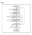
- Fig. 3 is a flowchart illustrating an outline of the simulation processing in the present embodiment.
- the member of staff P2 inputs the parameter information including the prescription information using the information input unit 12c of the tablet terminal 1 (step 101, in the following step is abbreviated to "S"), and the parameter information is transmitted from the communication I/F unit 11 of the tablet terminal 1 over the communication network 4 to the server device 3.
- the parameter information is received in the server device 3 by the communication I/F unit 31 and recognized by the acquired information recognition unit 32.
- the sort of lens design standard to be applied to the lens design data generation unit 33 is identified based on the recognition result, and, while applying the identified sort of lens design data, lens design data is generated for the spectacle lens the prospective spectacle lens wearer P1 is scheduled to wear (namely the spectacle lens corresponding to the determined prescription) (S102).
- a simulation image that reflects the lens visual performance identified by the lens design data is generated by the image generation unit 35 in the server device 3 (S103).
- Image data for the generated simulation image is then transmitted from the communication I/F unit 31 to the spectacle shop S side over the communication network 4.
- the image data from the server device 3 is received by the communication I/F unit 11 of the tablet terminal 1, and, under management by the tablet terminal 1, the image data is transmitted from the communication I/F unit 11 of the tablet terminal 1 to the HMD 2, so as to be received by the communication I/F unit 21 of the HMD 2. Accordingly, under management of the tablet terminal 1, the HMD 2 displays the simulation image generated by the server device 3 on the display screen unit 22 so as to let the prospective spectacle lens wearer P 1 check the simulation image by sight, and to let the prospective spectacle lens wearer P1 experience a simulation of a lens wearing state (S104).
- a lens order for the prospective spectacle lens wearer P1 is made at the spectacle shop S for the determined prescription or the like (S106).
- the procedure sequence described above is repeated again after changing the prescription or the like for the spectacle lens (S101 to S105), until the result of the simulated experience is OK.
- Simulation processing is thereby performed in a procedure such as that described above so as to let the prospective spectacle lens wearer P1 experience a simulated lens wearing state.
- Fig. 4 is a flowchart illustrating details of a characteristic procedure for simulation processing in the present embodiment.
- the lens design data generated by the lens design data generation unit 33, and identification information for the sort of lens design standard applied in the lens design data generation unit 33 during this data generation is acquired by the image generation unit 35 from the lens design data generation unit 33 (S201). Furthermore, the original image data 34a needed to generate the simulation image is acquired by the image generation unit 35 from the original image storage unit 34 (S202).
- the image processing unit 35a After acquiring the various data, information, etc., the image processing unit 35a generates the simulation image. Namely, the image processing unit 35a performs image processing to add blur, distortion, etc. corresponding to the acquired lens design data to the similarly acquired original image data 34a, and generates a simulation image that reflects the lens visual performance of the spectacle lens the prospective spectacle lens wearer P1 is scheduled to wear (S203).
- the simulation image not in the full visual area of the spectacle lens all at once, but in each partial visual area (namely, in each small visual area) which is obtained by dividing the full visual area into a plurality of small visual areas.
- the image superimposition unit 35b When this is performed, in the image generation unit 35 the image superimposition unit 35b generates the contour line image of the clearness index of the spectacle lens, and superimposes the contour line image on the simulation image (S204). A state is thereby obtained in which output can be performed from the server device 3 in a state in which the contour line image of the clearness index is superimposed on the partial visual field areas in the simulation image separately for each of the partial visual field areas.
- the control unit 37 reads the explanatory information 36a for each of the partial visual field areas from the explanatory information storage unit 36 (S205).
- the server device 3 In the tablet terminal 1, when, for example, there is a specific operation by the member of staff P2 operating the touch panel 12, first a request is made to the server device 3 to transmit the image data for the original image of the full visual field area. In response to the request, transmitted image data for the original image of the full visual field area arrives from the server device 3.
- the image data at this stage may be transmitted as image data for the original image separately for all the partial visual field areas constituting the full visual field area, or, when there are overlapping image portions between each of the partial visual field areas may be transmitted after combining so as to overlap overlapping image portions.
- the image data for the full visual field area of the original image may be transmitted as it is.
- the tablet terminal 1 When transmitted image data for the original image of the full visual field area arrives from the server device 3, the tablet terminal 1 receives the image data using the communication I/F unit 11.
- the information output unit 12a of the touch panel 12 then utilizes a specific portion on the display screen and performs display-output of the full visual field area worth of the sent original image (S206).
- the image display-output at this stage may display the original image for each of the partial visual field areas next to each other as they are, or by combining and displaying so as to overlap overlapping image portions in cases in which there are overlapping image portions present between each of the partial visual field areas.
- the member of staff P2 is able to appreciate the overall impression of the original image of the simulation image to be checked by sight by the prospective spectacle lens wearer P1. Details regarding the display-output mode of the full visual field area worth of the original image at this stage (including the positions of specific portions for display-output on the screen etc.) are described below (see, for example, Fig. 5 ).
- the information output unit 12a of the touch panel 12 utilizes a specific portion on the display screen to expand the selected and designated partial visual field area (namely the small visual field worth) of the simulation image onto which the contour line image has been superimposed (referred to below as “the small visual field worth of simulation image") by expansion of more than the display of the original image, and to perform display-output (S208).
- the information output unit 12a of the touch panel 12 utilizes a specific portion on the display screen to output and display the explanatory information 36a related to the selected and designated partial visual field area (namely the small visual field worth) (S209).
- the display-output mode of the small visual field worth of the simulation image and the explanatory information 36a is described later (see, for example, Fig. 5 ).
- Transmitted image data for the small visual field worth of the simulation image arriving from the tablet terminal 1 is received in the HMD 2 by the communication I/F unit 21.
- the display screen unit 22 of the HMD 2 then performs display-output of the sent small visual field worth of the simulation image (S210).
- the image display-output is performed separately for the left eye and right eye of the prospective spectacle lens wearer P1. This thereby enables what is referred to as 3D display to be performed for the prospective spectacle lens wearer P1. Showing such a display-output result gives the prospective spectacle lens wearer P1 the simulated experience of a lens wearing state.
- the image display-output of the display screen unit 22 at this time is for the small visual field worth, rather than for the full visual field area worth, of the simulation image.
- the display screen unit 22 is only capable of handling a visual field angle of about 50° in the diagonal direction, compared to a full visual field area through the spectacle lens of, for example, about 90° in the horizontal direction and about 70° in the vertical direction, the display screen unit 22 is able to perform image display-output without needing to shrink the simulation image or the like.
- the member of staff P2 reading out the display-output result of the explanatory information 36a, and notifying the display-output result to the prospective spectacle lens wearer P1, enables the prospective spectacle lens wearer P1 to be made sufficiently aware of the characteristics of the lens visual performance. Namely, by utilizing the display-output result of the explanatory information 36a on the tablet terminal 1, the prospective spectacle lens wearer P1 is able to be made appropriately and sufficiently aware of the characteristics of the lens visual performance of the spectacle lens selected by the prospective spectacle lens wearer P1, using accurate information based on the explanatory information 36a, rather than ambiguous information based on the memory of the member of staff P2.
- the tablet terminal 1 determines whether or not another partial visual field area has been selected and designated from out of the full visual field area worth of the original image, namely whether or not there has been an operation to switch the selected and designated partial visual field area (S211). Specifically, for example, determination is made as to whether or not an area switching operation to a different partial visual field area has been made to the full visual field area worth of the original image being output and displayed by the information output unit 12a, to the small visual field worth (partial visual field area) being display-output on the HMD 2, by whether or not a touch-operation has been made on the operation unit 12b of the touch panel 12 by the member of staff P2.
- the server device 3 the tablet terminal 1, and the HMD 2 end one sequence of the processing to generate and display-output the simulation image as described above, and get the prospective spectacle lens wearer P1 to determine the result of the simulated experience of the lens wearing state (see S104 of Fig. 3 ).
- the simulation system performing a simulation processing procedure such as that described above assists explanation regarding the spectacle lens to the prospective spectacle lens wearer P1 by the member of staff P2.
- the simulation system assists explanation by the member of staff P2 of the spectacle shop S by progressing in sequence through an image display step, in which a simulation image is selectively shown to the prospective spectacle lens wearer P1 separately for each of the partial visual field areas with the HMD 2, an information output step, in which the explanatory information 36a corresponding to the partial visual field area being display-output on the HMD 2 is output utilizing the tablet terminal 1, and a selection switching step of switching the selection of the partial visual field area being displayed by the HMD 2 and performing corresponding switching of the explanatory information 36a output by the tablet terminal 1.
- Fig. 5 is a schematic diagram illustrating a specific example of display-output content on the tablet terminal in the present embodiment.
- the full visual field area worth of an original image 13a is display-output on a part region, for example at the top left of the screen.
- This original image 13a is an example for a case in which each of the partial visual field areas that have been segmented into nine areas are display-output next to each other in a three row and three column pattern to as to recreate a state prior to being segmented.
- a partial visual field area selected and designated in the full visual field area worth of the original image 13a is display-output in an expanded state as the small visual field worth of the simulation image 13b.
- the small visual field worth of the simulation image 13b being display-output is that which has been selected and designated by the member of staff P2, and is that which is being display-output on the display screen unit 22 of the HMD 2.
- a text image 13c is display-output for the explanatory information corresponding to the partial visual field area selected and designated in the full visual field area worth of the original image 13a.
- the text image 13c for the explanatory information being display-output here is an image representing text to explain the characteristics of the lens visual perfonnance for the partial visual field area being display-output as the small visual field worth of the simulation image 13b.
- text such as "portion a has characteristic x", and "portion b has a wide application range of y" etc., is displayed and output as the text image 13c for the explanatory information.
- the small visual field worth of the simulation image 13b and the text image 13c for the explanatory information corresponding thereto in the display-output contents switch according to touch-operation employed on the full visual field area worth of the original image 13a.
- touch-operation is performed on one partial visual field area in the full visual field area worth of the original image 13a
- the corresponding small visual field worth of simulation image 13b and the text image 13c for the explanatory information is display-output; however, when this is followed by touch-operation of another partial visual field area, the display-output content is switched that of the corresponding small visual field worth of the simulation image 13b, and of the text image 13c for the explanatory information.
- the small visual field worth of the simulation image 13b and the text image 13c for the explanatory information is selectively display-output separately for each of the partial visual field areas.
- the original image in the illustrated example is the full visual field area of the spectacle lens segmented into nine partial visual field areas (small visual fields).
- the segmentation results in a right side portion, a central portion, and a left side portion of a far vision area, a right side portion, a central portion, and a left side portion of a near vision area, and a right side portion, a central portion, and a left side portion of an intermediate vision area, respectively belonging to separate partial visual field areas.
- Each of the partial visual field areas includes an image portion that overlaps with an adjacent partial visual field area.
- the original image for the central portion of the near vision area is envisaged as paper carrying text that is held up and read by the prospective spectacle lens wearer P1.
- Fig. 8 is an explanatory diagram illustrating a specific example of image showing contour lines of a spectacle lens clearness index.
- the contour line images in the illustrated example corresponds to the segmented original image separately for the partial visual field areas illustrated in Fig. 6 , and so are images with different display brightness according to the clearness index of the spectacle lens. Boundary portions between area portions having the same display brightness and adjacent area portions having another display brightness correspond to clearness index contour lines.
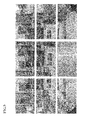
- Fig. 9 is an explanatory diagram illustrating a specific example of simulation images separate for partial visual field areas with contour line images of the clearness index superimposed.
- the image in the illustrated example is one in which the contour line images of Fig. 8 have been superimposed on the simulation images of Fig. 7 .
- the brightness of the images has been adjusted according to the values of the clearness index.
- the display screen unit 22 of the HMD 2 selectively outputs and displays such simulation images with the contour line images superimposed separately for each of the partial visual field areas.
- the explanatory information 36a corresponding to the small visual field worth (partial visual field area) being display-output on the display screen unit 22 of the HMD 2 is display-output to the member of staff P2 by the information output unit 12a of the tablet terminal 1.
- explanatory information 36a related to characteristics of the lens visual performance is pre-prepared by design type and separately for each of the partial visual field areas, and output of the explanatory information 36a corresponding to the display content is performed to match display of the simulation images to the prospective spectacle lens wearer P1.
- the member of staff P2 is thereby able to accurately confirm the characteristics of the lens visual performance by referencing the display-output result of the explanatory information 36a, even without completely memorizing the lens visual performance of the small visual field worth (the partial visual field area). Moreover, the member of staff P2 reading out the display-output result of the explanatory information 36a, and notifying the display-output result to the prospective spectacle lens wearer P1, also enables the prospective spectacle lens wearer P1 to be made sufficiently aware of the characteristics of the lens visual performance.
- the prospective spectacle lens wearer P1 can be made to determine the appropriateness or otherwise of the result of the simulated experience, enabling the prospective spectacle lens wearer P1 to be given a feeling of satisfaction.
- the simulation image is selectively displayed by the display screen unit 22 of the HMD 2 separately by small visual field worth (partial visual field area), to get the prospective spectacle lens wearer P1 to check by sight.
- display of the simulation images is selectively performed separately for plural partial visual field areas constituting the full visual field area, rather than being performed for the full visual field area of the spectacle lens all at once.
- the simulation system assists product explanation to the prospective spectacle lens wearer P1 regarding the spectacle lens, by the member of staff P2.
- the prospective spectacle lens wearer P1 is able to be made appropriately and sufficiently aware of the characteristics of the lens visual performance of the spectacle lens selected by the prospective spectacle lens wearer P1, using accurate information based on the explanatory information 36a, rather than ambiguous information based on the memory of the member of staff P2.
- reflected in the simulation images may not be completely reproducible when there is not sufficient resolution in the display screen unit 22, however, superimposing the contour line images enables the portions that cannot be completely reproduced to be supplemented by the contour lines; a low resolution is acceptable for the display screen unit 22, enabling the prospective spectacle lens wearer P1 to be given a virtual experience of a lens wearing state by using a compact and low cost HMD 2. Furthermore, the differences in the superimposed contour line images enables subtle differences in lens visual performance between each spectacle lens to be made apparent.
- display of the simulation images to the prospective spectacle lens wearer P1 is performed by employing the HMD 2 mounted to the head of the prospective spectacle lens wearer P1, and the display screen unit 22 of the HMD 2 operates separately for the left eye and right eye of the prospective spectacle lens wearer P1, respectively.
- the present embodiment is able to give the prospective spectacle lens wearer P1 a simulated experience of a lens wearing state, while suitably accommodating the special characteristics of spectacle lenses, where it is possible that spectacle lenses to be worn on the left and right eyes differ in prescription etc.
- the tablet terminal 1 employed on the spectacle shop S side communicates with the server device 3 over the communication network 4, and acquires the simulation image and the explanatory information 36a from the server device 3.
- the communication I/F unit 11 is provided in the tablet terminal 1 in order to acquire the simulation image and the explanatory information 36a
- the explanatory information storage unit 36 is provided in the server device 3 to store and retain the image generation unit 35 for generating the simulation image and the explanatory information 36a.
- the tablet terminal 1 is equipped with the information input unit 12c for inputting parameter information of the spectacle lens
- the server device 3 is equipped with the lens design data generation unit 33 for generating the lens design data of the spectacle lens while identifying the sort of lens design standard that should be applied based on the parameter information.
- the present embodiment is capable of performing processing from generation of lens design data to generation of simulation images as one processing sequence on the server device 3 side. Namely, efficiencies are achieved in processing execution on the server device 3 side. As viewed from the spectacle shop S side, transmitted simulation images etc. arrive from the server device 3 as long as parameter information etc. is input, and so there is a high convenience for both the prospective spectacle lens wearer P1 and the member of staffP2 of the spectacle shop S, respectively.
- the second embodiment to be explained differs from the first embodiment described above in the contents of the simulation images that are output by display.
- Fig. 10 is a flowchart illustrating an outline of simulation processing in the second embodiment.
- parameter information including prescription information, of the spectacle lens the prospective spectacle lens wearer P1 is to wear shape information of a spectacle frame for holding the spectacle lens, and the like is input to the information input unit 12c of the tablet terminal 1 (S301), and the parameter information is transmitted to the server device 3 over the communication network 4.
- the transmitted parameter information arrives in the server device 3 it is received by the communication I/F unit 31, and is recognized by the acquired information recognition unit 32.
- the acquired information recognition unit 32 acquires frame shape data identifying the frame shape of the spectacle frame based on the shape information of the spectacle frame included in the parameter information (S302).
- the lens design data generation unit 33 then, based on the recognition result of the prescription information etc. by the acquired information recognition unit 32, generates lens design data of the spectacle lens scheduled to be worn by the prospective spectacle lens wearer P1 (namely, a spectacle lens corresponding to the determined prescription etc.) (S303).
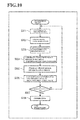
- Fig. 11 is a flowchart illustrating details of a characteristic procedure of the simulation processing in the second embodiment.
- the image generation unit 35 of the server device 3 acquires from the lens design data generation unit 33 the lens design data generated by the lens design data generation unit 33 at generation of the simulation image (see S304, S305 in Fig. 10 ), and the identification information for the sort of lens design standard the lens design data generation unit 33 applied when generating the data (S401).
- the image generation unit 35 then acquires the original image data 34a needed for generating the simulation image from the original image storage unit 34 (S402).
- the image generation unit 35 also acquires the frame shape data for the spectacle frame for holding the spectacle lens from the acquired information recognition unit 32 (S403).
- the image processing unit 35a in the image generation unit 35 After acquiring the various data and information etc., the image processing unit 35a in the image generation unit 35 generates the simulation image. Namely, the image processing unit 35a performs image processing to add blur, distortion, etc. corresponding to the acquired lens design data to the likewise acquired original image data 34a, and generates a simulation image that reflects the lens visual performance of the spectacle lens scheduled to be worn by the prospective spectacle lens wearer P1 (S404). A state is thereby obtained in which simulation images can be output from the server device 3 separately for each of the partial visual field areas (namely by small visual fields) of the full visual field area segmented into plural small visual fields, rather than for the full visual field area of the spectacle lens all at once.
- the partial visual field areas namely by small visual fields
- the image superimposition unit 35b in the image generation unit 35 When this is performed, the image superimposition unit 35b in the image generation unit 35 generates contour line images of a clearness index of the spectacle lens, and superimposes the contour line images on the simulation images (S405). A state is thereby obtained in which output from the server device 3 can be performed with the contour line images of the clearness index for the partial visual field areas in a superimposed state on the simulation images separately for each of the partial visual field areas.
- the image generation unit 35 employs these identification results to generate a frame image of the spectacle frame as it would be seen by the prospective spectacle lens wearer P1, and performs overlay processing on the simulation image by superimposing the frame image on the simulation images separately for each of the partial visual field areas.
- the frame image of the spectacle frame that would be seen in the partial visual filed is overlaid on the simulation image in each partial visual field, and in this state (namely, in a superimposition state), the simulation image can be outputted.
- the control unit 37 reads the explanatory information 36a for each of the partial visual field areas from the explanatory information storage unit 36 (S407).
- the control unit 37 transmits the image data and the explanatory information 36a to the tablet terminal 1 via the communication network 4 from the communication I/F unit 31 as required (for example, responding to a request from the tablet 1), wherein the image data is the data regarding the simulation image in each partial visual field area generated by the image generation unit 35, with the contour line image superimposed thereon and the frame image overlaid thereon, and the explanatory information 36 is the information read from the explanatory information storage unit 36.
- the original image on which the simulation image generation is based is similar to that of the first embodiment (see Fig. 6 ).
- Fig. 12 is an explanatory diagram illustrating a specific example in which a frame image is overlaid on simulation images obtained by performing the image processing on the original image.
- the simulation images of the illustrated example are obtained by performing image processing on each of the original images separately for the partial visual field areas illustrated in Fig. 6 .
- the frame image 50 corresponding to the frame of the spectacle frame is overlaid on the simulation image in each partial visual field area in the figure. Namely, the frame image 50 is superimposed on the simulation images.
- Such display-output content enables the prospective spectacle lens wearer P1 who is looking at them to easily and accurately ascertain the lens visual performance of the spectacle lens (the visual performance inside the frame) in a state in which the spectacle frame is being worn (namely a state in which the frame enters the field of view).
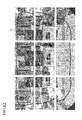
- Fig. 13 is an explanatory diagram illustrating a specific example in which a frame image is overlaid on the images showing contour lines of a clearness index of a spectacle lens.
- Fig. 14 is an explanatory diagram illustrating a specific example of a simulation image in each partial visual field area, on which contour line images are superimposed.
- the display-output content enable the prospective spectacle lens wearer P1 who is looking at them to easily and accurately ascertain the lens visual performance of the spectacle lens in a state in which the spectacle frame is being worn, and also to easily and accurately ascertain the distribution of the clearness index of the spectacle lens with respect to the position of the frame of the spectacle frame.
- the second embodiment obtains the following advantageous effects in addition to the advantageous effects obtained by the first embodiment as described above.
- simulation images may be displayed using a display device other than the HMD 2 (for example, by using a stationary display device).
- the terminal device that performs output of the explanatory information 36a etc. is the tablet terminal 1, as long as it is a terminal device capable of information input and output from and to the member of staff P2, output of the explanatory information 36a etc. may be performed using a terminal device other than the tablet terminal 1 (for example, a notebook or desktop type of personal computer).
- the member of staff P2 or the prospective spectacle lens wearer P1 may made to ascertain the explanatory information 36a through audio-output of the explanatory information 36a.
- configuration may be considered which at least one out of the tablet terminal 1 or the HMD 2 constituting the simulation device 5 is equipped with an information storage unit for storing the simulation images and the explanatory information 36a separately for each of the partial visual field areas, and the simulation images and the explanatory information 36a are retrieved and output from the information storage unit as required.
- segmentation into the partial visual field areas may be performed at the latest before the stage of simulation image generation by the image processing unit 35a.
- a configuration may be considered in which simulation images are generated for partial visual field areas as the original images of the partial visual field areas are being extracted from the full visual field area.
- the simulation images may be display-output in a state in which the contour line images are not superimposed. Similar applies to the display-output content of the display screen unit 22 of the HMD 2. Namely, in the display screen unit 22 of the HMD 2, a simulated experience a lens wearing state may be given to the prospective spectacle lens wearer P1 by displaying the simulation images as output in a state in which the contour line images are not superimposed.
- the image processing unit 35a generates simulation images by performing image processing to reflect the lens visual performance (blur, distortion, etc.) on the original image data 34a
- other image processing may also be performed at simulation image generation.
- An example of the other image processing is image processing to render effects of polarization, photochromatic, etc. Performing such incidental image processing enables generation of simulation images close to natural images even if the original image data 34a is the data regarding a CG image.
Landscapes
- Physics & Mathematics (AREA)
- Engineering & Computer Science (AREA)
- Health & Medical Sciences (AREA)
- General Physics & Mathematics (AREA)
- Life Sciences & Earth Sciences (AREA)
- Ophthalmology & Optometry (AREA)
- Theoretical Computer Science (AREA)
- Business, Economics & Management (AREA)
- General Health & Medical Sciences (AREA)
- Accounting & Taxation (AREA)
- Finance (AREA)
- Biomedical Technology (AREA)
- Biophysics (AREA)
- Veterinary Medicine (AREA)
- Public Health (AREA)
- Animal Behavior & Ethology (AREA)
- Mathematical Physics (AREA)
- Surgery (AREA)
- Molecular Biology (AREA)
- Medical Informatics (AREA)
- Optics & Photonics (AREA)
- Signal Processing (AREA)
- Heart & Thoracic Surgery (AREA)
- General Business, Economics & Management (AREA)
- Development Economics (AREA)
- Economics (AREA)
- Marketing (AREA)
- Strategic Management (AREA)
- Computer Graphics (AREA)
- Software Systems (AREA)
- General Engineering & Computer Science (AREA)
- Computer Hardware Design (AREA)
- Eyeglasses (AREA)
Applications Claiming Priority (2)
| Application Number | Priority Date | Filing Date | Title |
|---|---|---|---|
| JP2013021112 | 2013-02-06 | ||
| PCT/JP2013/080632 WO2014122834A1 (ja) | 2013-02-06 | 2013-11-13 | シミュレーションシステム、シミュレーション装置および商品説明補助方法 |
Publications (2)
| Publication Number | Publication Date |
|---|---|
| EP2958035A1 true EP2958035A1 (de) | 2015-12-23 |
| EP2958035A4 EP2958035A4 (de) | 2016-10-19 |
Family
ID=51299441
Family Applications (1)
| Application Number | Title | Priority Date | Filing Date |
|---|---|---|---|
| EP13874426.3A Withdrawn EP2958035A4 (de) | 2013-02-06 | 2013-11-13 | Simulationssystem, simulationsvorrichtung und verfahren zur unterstützung einer produktbeschreibung |
Country Status (6)
| Country | Link |
|---|---|
| US (1) | US10032297B2 (de) |
| EP (1) | EP2958035A4 (de) |
| JP (1) | JP6088549B2 (de) |
| KR (1) | KR101748976B1 (de) |
| CN (1) | CN105009124B (de) |
| WO (1) | WO2014122834A1 (de) |
Cited By (2)
| Publication number | Priority date | Publication date | Assignee | Title |
|---|---|---|---|---|
| EP3276327A1 (de) * | 2016-07-29 | 2018-01-31 | Essilor International | Verfahren zur virtuellen prüfung von mindestens einer linse mit einem vorbestimmten optischen merkmal und zugehörige vorrichtung |
| EP4372457A3 (de) * | 2017-03-05 | 2024-07-17 | Virtuoptica Ltd. | Augenuntersuchungsverfahren und vorrichtung dafür |
Families Citing this family (18)
| Publication number | Priority date | Publication date | Assignee | Title |
|---|---|---|---|---|
| DE102014116665B4 (de) * | 2014-09-22 | 2024-07-25 | Carl Zeiss Ag | Verfahren und Vorrichtungen zur Bestimmung der Augenrefraktion |
| WO2019009034A1 (ja) | 2017-07-03 | 2019-01-10 | 株式会社ニコン・エシロール | 眼鏡レンズの設計方法、眼鏡レンズの製造方法、眼鏡レンズ、眼鏡レンズ発注装置、眼鏡レンズ受注装置および眼鏡レンズ受発注システム |
| JP6882797B2 (ja) * | 2017-10-26 | 2021-06-02 | サン電子株式会社 | 会議システム |
| US10783700B2 (en) | 2018-05-20 | 2020-09-22 | Neurolens, Inc. | Progressive lens simulator with an axial power-distance simulator |
| US12121300B2 (en) | 2018-05-20 | 2024-10-22 | Neurolens, Inc. | Method of operating a progressive lens simulator with an axial power-distance simulator |
| US11559197B2 (en) | 2019-03-06 | 2023-01-24 | Neurolens, Inc. | Method of operating a progressive lens simulator with an axial power-distance simulator |
| US11175518B2 (en) | 2018-05-20 | 2021-11-16 | Neurolens, Inc. | Head-mounted progressive lens simulator |
| US11241151B2 (en) | 2019-03-07 | 2022-02-08 | Neurolens, Inc. | Central supervision station system for Progressive Lens Simulators |
| US11288416B2 (en) | 2019-03-07 | 2022-03-29 | Neurolens, Inc. | Deep learning method for a progressive lens simulator with an artificial intelligence engine |
| US11259697B2 (en) | 2019-03-07 | 2022-03-01 | Neurolens, Inc. | Guided lens design exploration method for a progressive lens simulator |
| US11202563B2 (en) | 2019-03-07 | 2021-12-21 | Neurolens, Inc. | Guided lens design exploration system for a progressive lens simulator |
| US11259699B2 (en) | 2019-03-07 | 2022-03-01 | Neurolens, Inc. | Integrated progressive lens simulator |
| JP6997129B2 (ja) * | 2019-03-28 | 2022-01-17 | ファナック株式会社 | 制御システム |
| CN111093027B (zh) | 2019-12-31 | 2021-04-13 | 联想(北京)有限公司 | 一种显示方法及电子设备 |
| US11960146B2 (en) | 2020-02-21 | 2024-04-16 | Ditto Technologies, Inc. | Fitting of glasses frames including live fitting |
| JP7272985B2 (ja) * | 2020-03-23 | 2023-05-12 | ホヤ レンズ タイランド リミテッド | 仮想画像生成装置及び仮想画像生成方法 |
| WO2021214057A1 (en) * | 2020-04-21 | 2021-10-28 | Essilor International | Method of manufacturing an ophthalmic lens |
| WO2022138073A1 (ja) * | 2020-12-21 | 2022-06-30 | 株式会社ニコン・エシロール | 画像生成装置、頭部装着表示装置、画像生成方法、及びプログラム |
Family Cites Families (15)
| Publication number | Priority date | Publication date | Assignee | Title |
|---|---|---|---|---|
| JP3919097B2 (ja) | 2001-09-06 | 2007-05-23 | Hoya株式会社 | 眼鏡レンズの両眼視性能表示方法及びその装置 |
| ATE305605T1 (de) * | 2001-09-06 | 2005-10-15 | Hoya Corp | Verfahren zur beurteilung der binokularen eigenschaften von brillengläsern, vorrichtung zur anzeige dieser eigenschaften und zugehöriger apparat |
| CN101356468B (zh) * | 2005-11-15 | 2010-12-22 | 卡尔蔡司视觉澳大利亚控股有限公司 | 眼镜片模拟系统和方法 |
| JP4931669B2 (ja) * | 2007-03-29 | 2012-05-16 | 株式会社ニコン・エシロール | 眼鏡レンズ受発注システム |
| JP5073521B2 (ja) | 2007-09-28 | 2012-11-14 | 株式会社ニデック | 検眼装置 |
| JP4609581B2 (ja) * | 2008-03-26 | 2011-01-12 | セイコーエプソン株式会社 | シミュレーション装置、シミュレーションプログラムおよびシミュレーションプログラムを記録した記録媒体 |
| US8690323B2 (en) | 2008-04-28 | 2014-04-08 | Hoya Corporation | Method of selecting lens design standard |
| JP5341462B2 (ja) * | 2008-10-14 | 2013-11-13 | キヤノン株式会社 | 収差補正方法、画像処理装置および画像処理システム |
| EP2341388A1 (de) | 2008-10-17 | 2011-07-06 | Hoya Corporation | Sichtfeld-bildanzeigevorrichtung für brillen und verfahren zur sichtfeldbildanzeige für brillen |
| ATE509568T1 (de) | 2008-10-22 | 2011-06-15 | Sensomotoric Instr Ges Fuer Innovative Sensorik Mbh | Verfahren und vorrichtung zur bildverarbeitung für computerunterstützte augenoperationen |
| US8583406B2 (en) * | 2008-11-06 | 2013-11-12 | Hoya Lens Manufacturing Philippines Inc. | Visual simulator for spectacle lens, visual simulation method for spectacle lens, and computer readable recording medium recording computer readable visual simulation program for spectacle lens |
| US20110213664A1 (en) * | 2010-02-28 | 2011-09-01 | Osterhout Group, Inc. | Local advertising content on an interactive head-mounted eyepiece |
| US20130278631A1 (en) * | 2010-02-28 | 2013-10-24 | Osterhout Group, Inc. | 3d positioning of augmented reality information |
| JP5632245B2 (ja) * | 2010-09-27 | 2014-11-26 | Hoya株式会社 | 眼鏡の視野画像表示装置 |
| CA2820241C (en) * | 2012-06-13 | 2020-01-14 | Robert G. Hilkes | An apparatus and method for enhancing human visual performance in a head worn video system |
-
2013
- 2013-11-13 KR KR1020157023939A patent/KR101748976B1/ko not_active Expired - Fee Related
- 2013-11-13 CN CN201380072146.0A patent/CN105009124B/zh not_active Expired - Fee Related
- 2013-11-13 EP EP13874426.3A patent/EP2958035A4/de not_active Withdrawn
- 2013-11-13 US US14/766,277 patent/US10032297B2/en not_active Expired - Fee Related
- 2013-11-13 JP JP2014560642A patent/JP6088549B2/ja not_active Expired - Fee Related
- 2013-11-13 WO PCT/JP2013/080632 patent/WO2014122834A1/ja not_active Ceased
Cited By (3)
| Publication number | Priority date | Publication date | Assignee | Title |
|---|---|---|---|---|
| EP3276327A1 (de) * | 2016-07-29 | 2018-01-31 | Essilor International | Verfahren zur virtuellen prüfung von mindestens einer linse mit einem vorbestimmten optischen merkmal und zugehörige vorrichtung |
| US10310269B2 (en) | 2016-07-29 | 2019-06-04 | Essilor International | Method for virtual testing of at least one lens having a predetermined optical feature and associated device |
| EP4372457A3 (de) * | 2017-03-05 | 2024-07-17 | Virtuoptica Ltd. | Augenuntersuchungsverfahren und vorrichtung dafür |
Also Published As
| Publication number | Publication date |
|---|---|
| EP2958035A4 (de) | 2016-10-19 |
| JPWO2014122834A1 (ja) | 2017-01-26 |
| JP6088549B2 (ja) | 2017-03-01 |
| KR20150114995A (ko) | 2015-10-13 |
| CN105009124B (zh) | 2018-01-19 |
| US20150371415A1 (en) | 2015-12-24 |
| KR101748976B1 (ko) | 2017-06-19 |
| US10032297B2 (en) | 2018-07-24 |
| CN105009124A (zh) | 2015-10-28 |
| WO2014122834A1 (ja) | 2014-08-14 |
Similar Documents
| Publication | Publication Date | Title |
|---|---|---|
| US10032297B2 (en) | Simulation system, simulation device, and product explanation assistance method | |
| JP7339386B2 (ja) | 視線追跡方法、視線追跡装置、端末デバイス、コンピュータ可読記憶媒体及びコンピュータプログラム | |
| US10043318B2 (en) | Display synchronized image warping | |
| JP6801263B2 (ja) | 表示制御プログラム、表示制御方法および表示制御装置 | |
| JP6411505B2 (ja) | 全焦点画像を生成するための方法および装置 | |
| US20170153712A1 (en) | Input system and input method | |
| JP6276691B2 (ja) | シミュレーション装置、シミュレーションシステム、シミュレーション方法及びシミュレーションプログラム | |
| EP2674920A1 (de) | Objektanzeigevorrichtung, objektanzeigeverfahren und objektanzeigeprogramm | |
| CN110378914A (zh) | 基于注视点信息的渲染方法及装置、系统、显示设备 | |
| CN109791431A (zh) | 视点渲染 | |
| CN109696953B (zh) | 虚拟现实文字显示的方法、装置和虚拟现实设备 | |
| JP5098739B2 (ja) | シミュレーション装置、シミュレーションプログラムおよびシミュレーションプログラムを記録した記録媒体 | |
| CN105380591A (zh) | 视力检测装置、系统及方法 | |
| CN108259883A (zh) | 图像处理方法、头戴式显示器以及可读存储介质 | |
| CN107728986B (zh) | 一种双显示屏的显示方法以及显示装置 | |
| US20190204597A1 (en) | Image processing method and apparatus in virtual reality device | |
| US20200066234A1 (en) | VR Drawing Method, Device, and System | |
| US10586392B2 (en) | Image display apparatus using foveated rendering | |
| JP2017224141A (ja) | 情報表示装置 | |
| CN106598258A (zh) | 注视点映射函数确定方法及装置、注视点确定方法及装置 | |
| US20220114636A1 (en) | System and method for customization of an eyewear | |
| KR20190041293A (ko) | 증강 현실 표시 방법 및 장치 | |
| CN105872547A (zh) | 一种图像处理方法及装置 | |
| CN107742316A (zh) | 图像拼接点获取方法及获取装置 | |
| US20260011067A1 (en) | Method and apparatus for rendering drm content in xr device, device, and medium |
Legal Events
| Date | Code | Title | Description |
|---|---|---|---|
| PUAI | Public reference made under article 153(3) epc to a published international application that has entered the european phase |
Free format text: ORIGINAL CODE: 0009012 |
|
| 17P | Request for examination filed |
Effective date: 20150907 |
|
| AK | Designated contracting states |
Kind code of ref document: A1 Designated state(s): AL AT BE BG CH CY CZ DE DK EE ES FI FR GB GR HR HU IE IS IT LI LT LU LV MC MK MT NL NO PL PT RO RS SE SI SK SM TR |
|
| AX | Request for extension of the european patent |
Extension state: BA ME |
|
| DAX | Request for extension of the european patent (deleted) | ||
| A4 | Supplementary search report drawn up and despatched |
Effective date: 20160920 |
|
| RIC1 | Information provided on ipc code assigned before grant |
Ipc: G06F 17/50 20060101AFI20160914BHEP Ipc: A61B 3/10 20060101ALI20160914BHEP Ipc: G06T 19/00 20110101ALI20160914BHEP Ipc: G02C 13/00 20060101ALI20160914BHEP |
|
| 17Q | First examination report despatched |
Effective date: 20191127 |
|
| STAA | Information on the status of an ep patent application or granted ep patent |
Free format text: STATUS: THE APPLICATION HAS BEEN WITHDRAWN |
|
| 18W | Application withdrawn |
Effective date: 20200318 |