EP2958225A2 - Procédé de fonctionnement d'un convertisseur modulaire multi-étagé comprenant un circuit intermédiaire de tension - Google Patents
Procédé de fonctionnement d'un convertisseur modulaire multi-étagé comprenant un circuit intermédiaire de tension Download PDFInfo
- Publication number
- EP2958225A2 EP2958225A2 EP15169194.6A EP15169194A EP2958225A2 EP 2958225 A2 EP2958225 A2 EP 2958225A2 EP 15169194 A EP15169194 A EP 15169194A EP 2958225 A2 EP2958225 A2 EP 2958225A2
- Authority
- EP
- European Patent Office
- Prior art keywords
- voltage
- power converter
- energy storage
- storage means
- phase
- Prior art date
- Legal status (The legal status is an assumption and is not a legal conclusion. Google has not performed a legal analysis and makes no representation as to the accuracy of the status listed.)
- Withdrawn
Links
- 238000000034 method Methods 0.000 title abstract description 15
- 238000004146 energy storage Methods 0.000 abstract description 26
- 239000003990 capacitor Substances 0.000 description 7
- 239000004065 semiconductor Substances 0.000 description 4
- 230000005540 biological transmission Effects 0.000 description 3
- 238000007796 conventional method Methods 0.000 description 3
- 238000010586 diagram Methods 0.000 description 2
- 230000010355 oscillation Effects 0.000 description 2
- 238000010276 construction Methods 0.000 description 1
- 238000009826 distribution Methods 0.000 description 1
- 230000001105 regulatory effect Effects 0.000 description 1
Images
Classifications
-
- H—ELECTRICITY
- H02—GENERATION; CONVERSION OR DISTRIBUTION OF ELECTRIC POWER
- H02M—APPARATUS FOR CONVERSION BETWEEN AC AND AC, BETWEEN AC AND DC, OR BETWEEN DC AND DC, AND FOR USE WITH MAINS OR SIMILAR POWER SUPPLY SYSTEMS; CONVERSION OF DC OR AC INPUT POWER INTO SURGE OUTPUT POWER; CONTROL OR REGULATION THEREOF
- H02M7/00—Conversion of AC power input into DC power output; Conversion of DC power input into AC power output
- H02M7/42—Conversion of DC power input into AC power output without possibility of reversal
- H02M7/44—Conversion of DC power input into AC power output without possibility of reversal by static converters
- H02M7/48—Conversion of DC power input into AC power output without possibility of reversal by static converters using discharge tubes with control electrode or semiconductor devices with control electrode
- H02M7/483—Converters with outputs that each can have more than two voltages levels
-
- H—ELECTRICITY
- H02—GENERATION; CONVERSION OR DISTRIBUTION OF ELECTRIC POWER
- H02M—APPARATUS FOR CONVERSION BETWEEN AC AND AC, BETWEEN AC AND DC, OR BETWEEN DC AND DC, AND FOR USE WITH MAINS OR SIMILAR POWER SUPPLY SYSTEMS; CONVERSION OF DC OR AC INPUT POWER INTO SURGE OUTPUT POWER; CONTROL OR REGULATION THEREOF
- H02M7/00—Conversion of AC power input into DC power output; Conversion of DC power input into AC power output
- H02M7/42—Conversion of DC power input into AC power output without possibility of reversal
- H02M7/44—Conversion of DC power input into AC power output without possibility of reversal by static converters
- H02M7/48—Conversion of DC power input into AC power output without possibility of reversal by static converters using discharge tubes with control electrode or semiconductor devices with control electrode
- H02M7/483—Converters with outputs that each can have more than two voltages levels
- H02M7/4835—Converters with outputs that each can have more than two voltages levels comprising two or more cells, each including a switchable capacitor, the capacitors having a nominal charge voltage which corresponds to a given fraction of the input voltage, and the capacitors being selectively connected in series to determine the instantaneous output voltage
-
- H—ELECTRICITY
- H02—GENERATION; CONVERSION OR DISTRIBUTION OF ELECTRIC POWER
- H02M—APPARATUS FOR CONVERSION BETWEEN AC AND AC, BETWEEN AC AND DC, OR BETWEEN DC AND DC, AND FOR USE WITH MAINS OR SIMILAR POWER SUPPLY SYSTEMS; CONVERSION OF DC OR AC INPUT POWER INTO SURGE OUTPUT POWER; CONTROL OR REGULATION THEREOF
- H02M7/00—Conversion of AC power input into DC power output; Conversion of DC power input into AC power output
- H02M7/42—Conversion of DC power input into AC power output without possibility of reversal
- H02M7/44—Conversion of DC power input into AC power output without possibility of reversal by static converters
- H02M7/48—Conversion of DC power input into AC power output without possibility of reversal by static converters using discharge tubes with control electrode or semiconductor devices with control electrode
- H02M7/53—Conversion of DC power input into AC power output without possibility of reversal by static converters using discharge tubes with control electrode or semiconductor devices with control electrode using devices of a triode or transistor type requiring continuous application of a control signal
- H02M7/537—Conversion of DC power input into AC power output without possibility of reversal by static converters using discharge tubes with control electrode or semiconductor devices with control electrode using devices of a triode or transistor type requiring continuous application of a control signal using semiconductor devices only, e.g. single switched pulse inverters
- H02M7/539—Conversion of DC power input into AC power output without possibility of reversal by static converters using discharge tubes with control electrode or semiconductor devices with control electrode using devices of a triode or transistor type requiring continuous application of a control signal using semiconductor devices only, e.g. single switched pulse inverters with automatic control of output wave form or frequency
- H02M7/5395—Conversion of DC power input into AC power output without possibility of reversal by static converters using discharge tubes with control electrode or semiconductor devices with control electrode using devices of a triode or transistor type requiring continuous application of a control signal using semiconductor devices only, e.g. single switched pulse inverters with automatic control of output wave form or frequency by pulse-width modulation
Definitions
- the invention relates to a method for operating a voltage intermediate circuit having a modular multistage converter having a plurality of converter modules, each converter module comprises a series circuit of submodules and each submodule is associated with a voltage interval and switching elements and an energy storage means, wherein a power converter module to increase the headroom one Shifting voltage between zero points of the modular multi-stage converter on the AC voltage and the DC side generating zero system voltage is switched.
- Such a modular multistage power converter is also referred to as a modular multilevel power converter (MMC).
- MMC modular multilevel power converter
- the submodules which are also referred to as phase elements, each comprise an arrangement of switching elements which each have at least two turn-off power semiconductors and at least two freewheeling diodes and energy storage means connected in parallel thereto.
- WO 2007/028349 A1 is a modular multi-stage power converter with multiple power converter modules known.
- Such devices have, for example, two rectifiers connected on the DC side in order to transmit electrical energy between two electrically separate AC voltage networks and to control this transmission in a targeted manner. Such a control is necessary because in AC networks local overloads or unequal load distributions may occur. These overloads can be compensated by the regulated energy transfer.
- HVDC high-voltage DC transmission
- VSC Voltage Source Converter
- an energy storage means eg. As a capacitor needed.
- Such an HVDC system usually comprises a first converter as a converter for converting the AC voltage into a DC voltage, a transmission cable as a DC voltage line and a second converter as a converter for converting the DC voltage into an AC voltage.
- a power converter comprises a plurality of branches, wherein an upper and a lower branch together form a phase module, which is also referred to as a converter phase.
- phase module comprises a plurality of submodules arranged in series with switching elements, wherein a switching element has two power semiconductors, two diodes and a capacitor as energy storage means.
- the power semiconductors are electronic switches, z. IGBTs.
- WO 2007/028349 A1 is described as an example of a power converter, a H-circuit, which is used in an HVDC system.
- the maximum realizable amplitude of the AC output voltage through the intermediate circuit voltage of the central energy storage means, the z. B. may be formed as a storage capacitor determined.
- the ratio of the sum voltage of the energy storage means to the amplitude of the module voltage of the associated power converter module is called the degree of duty for which an upper limit exists.
- a zero system voltage also referred to as a zero system
- a zero system is a voltage shift between the natural zero points of a converter on the AC and DC sides, increasing the duty cycle.
- the invention is therefore based on the object to provide a method for operating a voltage intermediate circuit having a modular multistage power converter, in which permanently a control reserve is present.
- amplitude and phase of the output voltage of a power converter module by means of the zero system voltage can be chosen so that the largest possible control reserve is obtained taking into account the voltage of the energy storage means.
- the application of a zero system voltage causes a voltage shift between the zero point of the MMC and the voltages on the AC side of the multi-stage converter, thereby allowing an increase in the headroom.
- the amplitude and phase position of the output voltage of a converter module are selected by means of the zero system so that there is sufficient reserve reserve at all times. This means that the over time changing voltage of the energy storage means is always higher than the output voltage of a power converter module, so that a transfer of energy from the energy storage means to the or the converter modules is possible.
- the invention provides the advantage that with a constant headroom, the number of submodules can be reduced. Alternatively or additionally, the size of the energy storage means can be reduced.
- the time profile of the voltage of the energy storage means is taken into account, whereby the drive reserve can be further increased, while in a conventional method only the amplitude of the output voltage with respect to the zero point of the power converter is minimized.
- the sum of the voltages of all energy storage means of a power converter module is preferably taken into account.
- the disadvantage of the conventional method is eliminated by the method according to the invention by modifying the output voltage of the multistage converter by means of the connected zero system voltage such that there is always a maximum possible voltage difference, and thus a maximum possible drive reserve can be achieved at any time.
- a capacitor is used as energy storage means.
- the voltages of the energy storage means of all six converter modules are shifted, ie, for example, the voltages of the six capacitors are shifted.
- a zero system voltage based on the 3rd harmonic is applied.
- any other zero system can also be activated.
- a zero system voltage based on the 3rd harmonic is particularly well suited for reducing the harmonic content.
- a zero system voltage based on balanced sine modulation can be applied.
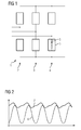
- Fig. 1 shows a conventional modular multi-stage power converter 1, which is provided for a three-phase AC power network and three phase modules 2, 3, 4, which are also referred to as power converter modules.
- Each phase module is connected to one phase of the AC voltage network.
- the phase modules 2, 3, 4 comprise a total of six converter modules 5, each having a plurality of serially connected submodules 6, each associated with a voltage interval.
- Each submodule 6 has switching elements and an energy storage device.
- the conventional modular multistage power converter in this case comprises six single-phase converters with a power converter module for each upper and lower branch.
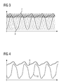
- Fig. 2 the course of the module voltage of a single conventional power converter module is shown, of which, as already mentioned six are present, between each of which a phase difference is present.
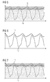
- Fig. 3 shows the voltage curves of all six converter modules of the multi-stage converter.
- the course of the voltage 7 of an energy storage means is shown, which is formed in the illustrated embodiment as a capacitor.
- the time is plotted on the horizontal axis and the voltage of the phase of a converter module is plotted on the vertical axis.
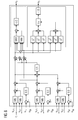
- Fig. 4 and 5 are similar diagrams like that Fig. 2 and 3 and show the time characteristic of the voltage of an energy storage means designated by the reference numeral 9 and the time profile of the voltage of a power converter module designated by the reference numeral 10 when carrying out the method.
- Fig. 5 shows the time course of the voltages of all six converter modules.
- the multistage power converter has a zero system, that is, a zero system voltage, based on the 3rd harmonic.
- the six voltages of the converter modules serve as input variables when calculating the zero system. After calculating the zero-sequence voltage, this is applied to the fundamental oscillation, ie the basic oscillation is superimposed.
- the 6 and 7 show an embodiment of the method for operating the multi-stage converter, in which a balanced sine-modulation based zero system is switched. Symmetrical sine modulation is also referred to as space vector modulation. From the current voltages, a correction system is formed as the -0.5 times the sum of the largest and smallest voltage value. This zero system is then added to the voltages, resulting in the in the 6 and 7 shown voltage curves.
- the reference numeral 11 denotes the Voltage of the energy storage means, the reference numeral 12, the course of a voltage of a power converter module.
- Fig. 7 shows the curves of all six voltages 12 of the converter modules.
- Fig. 8 is a diagram and shows schematically the calculation of the zero system, where both variants described, ie both in the Fig. 4 and 5 shown superimposition of a based on the 3rd harmonic zero system as well as in the 6 and 7 shown superimposition of a symmetrical sine modulation based zero system are included.
- the six voltages of the converter modules of the basic system are used as input variables, whereby a positive value and a negative value are taken into account.
- the calculation of the zero system based on symmetrical sine modulation is shown on the top right, and the calculation of the third system based on the third harmonic is shown on the bottom right.
Landscapes
- Engineering & Computer Science (AREA)
- Power Engineering (AREA)
- Inverter Devices (AREA)
- Rectifiers (AREA)
Applications Claiming Priority (1)
| Application Number | Priority Date | Filing Date | Title |
|---|---|---|---|
| DE102014211892.1A DE102014211892A1 (de) | 2014-06-20 | 2014-06-20 | Verfahren zum Betreiben eines einen Spannungszwischenkreis aufweisenden modularen Mehrstufenstromrichters |
Publications (2)
| Publication Number | Publication Date |
|---|---|
| EP2958225A2 true EP2958225A2 (fr) | 2015-12-23 |
| EP2958225A3 EP2958225A3 (fr) | 2016-05-25 |
Family
ID=53191612
Family Applications (1)
| Application Number | Title | Priority Date | Filing Date |
|---|---|---|---|
| EP15169194.6A Withdrawn EP2958225A3 (fr) | 2014-06-20 | 2015-05-26 | Procédé de fonctionnement d'un convertisseur modulaire multi-étagé comprenant un circuit intermédiaire de tension |
Country Status (2)
| Country | Link |
|---|---|
| EP (1) | EP2958225A3 (fr) |
| DE (1) | DE102014211892A1 (fr) |
Cited By (2)
| Publication number | Priority date | Publication date | Assignee | Title |
|---|---|---|---|---|
| WO2022012759A1 (fr) * | 2020-07-17 | 2022-01-20 | Siemens Aktiengesellschaft | Commande d'un convertisseur de puissance à niveaux multiples |
| CN119030351A (zh) * | 2024-10-29 | 2024-11-26 | 山东大学 | 一种面向过载运行需求的mmc交流母线电压选取方法 |
Citations (1)
| Publication number | Priority date | Publication date | Assignee | Title |
|---|---|---|---|---|
| WO2007028349A1 (fr) | 2005-09-09 | 2007-03-15 | Siemens Aktiengesellschaft | Dispositif de transmission d'energie electrique |
-
2014
- 2014-06-20 DE DE102014211892.1A patent/DE102014211892A1/de not_active Withdrawn
-
2015
- 2015-05-26 EP EP15169194.6A patent/EP2958225A3/fr not_active Withdrawn
Patent Citations (1)
| Publication number | Priority date | Publication date | Assignee | Title |
|---|---|---|---|---|
| WO2007028349A1 (fr) | 2005-09-09 | 2007-03-15 | Siemens Aktiengesellschaft | Dispositif de transmission d'energie electrique |
Cited By (3)
| Publication number | Priority date | Publication date | Assignee | Title |
|---|---|---|---|---|
| WO2022012759A1 (fr) * | 2020-07-17 | 2022-01-20 | Siemens Aktiengesellschaft | Commande d'un convertisseur de puissance à niveaux multiples |
| US12413157B2 (en) | 2020-07-17 | 2025-09-09 | Siemens Energy Global GmbH & Co. KG | Controlling a multilevel power converter |
| CN119030351A (zh) * | 2024-10-29 | 2024-11-26 | 山东大学 | 一种面向过载运行需求的mmc交流母线电压选取方法 |
Also Published As
| Publication number | Publication date |
|---|---|
| EP2958225A3 (fr) | 2016-05-25 |
| DE102014211892A1 (de) | 2015-12-24 |
Similar Documents
| Publication | Publication Date | Title |
|---|---|---|
| EP2432109B1 (fr) | Commutateur modulaire pour un convertisseur électrique, convertisseur électrique et procédé de fonctionnement d'un convertisseur électrique | |
| EP3496259B1 (fr) | Système de convertisseur électrique | |
| AT406434B (de) | Vorrichtung zur umformung eines dreiphasigen spannungssystems in eine vorgebbare, einen verbraucher speisende gleichspannung | |
| EP2107672A1 (fr) | Onduleur triphasé sans connexion entre le conducteur de neutre du réseau et le point milieu du circuit intermédiaire | |
| EP3002866B1 (fr) | Convertisseur de circuit de tension intermédiaire dans une topologie à cinq points | |
| EP2845288B1 (fr) | Couplage ou découplage de puissance dans une dérivation à un noeud de un réseau dc par une source de tension connectée en série | |
| EP3136581A1 (fr) | Convertisseur de frequence multipoints modulaire et son procede de fonctionnement | |
| EP2992595A1 (fr) | Ensemble mutateur à mutateurs multi-étages câblés en parallèle et son procédé de commande | |
| EP2807738B1 (fr) | Convertisseur à cellules multiples | |
| DE102011086087A1 (de) | Elektrischer Umrichter | |
| EP2928060A1 (fr) | Circuit de convertisseur modulaire doté de sous-modules présentant différentes capacités de commutation | |
| EP3195440B1 (fr) | Procede de transmission d'énergie électrique entre un réseau à courant alternatif et un réseau à courant continue | |
| EP3138176B1 (fr) | Convertisseur servant à la compensation symétrique d'énergie réactive et procédé permettant le réglage dudit convertisseur | |
| EP2958225A2 (fr) | Procédé de fonctionnement d'un convertisseur modulaire multi-étagé comprenant un circuit intermédiaire de tension | |
| EP3353885B1 (fr) | Procédé de fonctionnement d'un convertisseur de courant modulaire à multiples niveaux, convertisseur de courant modulaire à multiples niveaux ainsi que programme d'ordinateur | |
| DE19843692C2 (de) | Wechselrichter für die Einspeisung sinusförmiger Ströme in ein Wechselstromnetz | |
| WO2016091300A1 (fr) | Convertisseur continu-continu bidirectionnel à circuit intermédiaire divisé | |
| DE102013109714A1 (de) | Verfahren zum Betreiben einer elektrischen Schaltung sowie elektrische Schaltung | |
| EP3331118B1 (fr) | Installation de transfert d'énergie électrique | |
| DE102015008369A1 (de) | Schaltungsanordnung zur bidirektionalen Kopplung eines Gleichspannungssystems mit mehreren Wechselspannungssystemen und Verfahren zur Steuerung einer solchen Schaltungsanordnung | |
| EP3639352B1 (fr) | Ensemble convertisseur de puissance présentant une capacité de coupure d'un courant de fuite et procédé pour la coupure d'un courant de fuite pour ledit ensemble convertisseur de puissance | |
| EP3556003B1 (fr) | Convertisseur multi-niveaux et procédé de fonctionnement | |
| DE202016102164U1 (de) | Stromrichter mit Überspannungsableiter | |
| EP2928055B1 (fr) | Convertisseur de courant modulaire et procédé de production d'une tension de sortie sinusoïdale à harmoniques réduites | |
| EP3883116B1 (fr) | Véhicule, en particulier véhicule ferroviaire |
Legal Events
| Date | Code | Title | Description |
|---|---|---|---|
| PUAI | Public reference made under article 153(3) epc to a published international application that has entered the european phase |
Free format text: ORIGINAL CODE: 0009012 |
|
| AK | Designated contracting states |
Kind code of ref document: A2 Designated state(s): AL AT BE BG CH CY CZ DE DK EE ES FI FR GB GR HR HU IE IS IT LI LT LU LV MC MK MT NL NO PL PT RO RS SE SI SK SM TR |
|
| AX | Request for extension of the european patent |
Extension state: BA ME |
|
| PUAL | Search report despatched |
Free format text: ORIGINAL CODE: 0009013 |
|
| AK | Designated contracting states |
Kind code of ref document: A3 Designated state(s): AL AT BE BG CH CY CZ DE DK EE ES FI FR GB GR HR HU IE IS IT LI LT LU LV MC MK MT NL NO PL PT RO RS SE SI SK SM TR |
|
| AX | Request for extension of the european patent |
Extension state: BA ME |
|
| RIC1 | Information provided on ipc code assigned before grant |
Ipc: H02M 7/5395 20060101ALI20160418BHEP Ipc: H02M 7/483 20070101AFI20160418BHEP |
|
| STAA | Information on the status of an ep patent application or granted ep patent |
Free format text: STATUS: THE APPLICATION IS DEEMED TO BE WITHDRAWN |
|
| 18D | Application deemed to be withdrawn |
Effective date: 20161126 |