EP2958729B1 - Formsystem umfassend einen aktuator - Google Patents
Formsystem umfassend einen aktuator Download PDFInfo
- Publication number
- EP2958729B1 EP2958729B1 EP14754918.2A EP14754918A EP2958729B1 EP 2958729 B1 EP2958729 B1 EP 2958729B1 EP 14754918 A EP14754918 A EP 14754918A EP 2958729 B1 EP2958729 B1 EP 2958729B1
- Authority
- EP
- European Patent Office
- Prior art keywords
- platen
- clamp
- actuator
- compensator
- linear actuator
- Prior art date
- Legal status (The legal status is an assumption and is not a legal conclusion. Google has not performed a legal analysis and makes no representation as to the accuracy of the status listed.)
- Active
Links
Images




Classifications
-
- B—PERFORMING OPERATIONS; TRANSPORTING
- B29—WORKING OF PLASTICS; WORKING OF SUBSTANCES IN A PLASTIC STATE IN GENERAL
- B29C—SHAPING OR JOINING OF PLASTICS; SHAPING OF MATERIAL IN A PLASTIC STATE, NOT OTHERWISE PROVIDED FOR; AFTER-TREATMENT OF THE SHAPED PRODUCTS, e.g. REPAIRING
- B29C45/00—Injection moulding, i.e. forcing the required volume of moulding material through a nozzle into a closed mould; Apparatus therefor
- B29C45/17—Component parts, details or accessories; Auxiliary operations
- B29C45/64—Mould opening, closing or clamping devices
- B29C45/66—Mould opening, closing or clamping devices mechanical
-
- B—PERFORMING OPERATIONS; TRANSPORTING
- B29—WORKING OF PLASTICS; WORKING OF SUBSTANCES IN A PLASTIC STATE IN GENERAL
- B29C—SHAPING OR JOINING OF PLASTICS; SHAPING OF MATERIAL IN A PLASTIC STATE, NOT OTHERWISE PROVIDED FOR; AFTER-TREATMENT OF THE SHAPED PRODUCTS, e.g. REPAIRING
- B29C45/00—Injection moulding, i.e. forcing the required volume of moulding material through a nozzle into a closed mould; Apparatus therefor
- B29C45/17—Component parts, details or accessories; Auxiliary operations
- B29C45/1761—Means for guiding movable mould supports or injection units on the machine base or frame; Machine bases or frames
-
- B—PERFORMING OPERATIONS; TRANSPORTING
- B29—WORKING OF PLASTICS; WORKING OF SUBSTANCES IN A PLASTIC STATE IN GENERAL
- B29C—SHAPING OR JOINING OF PLASTICS; SHAPING OF MATERIAL IN A PLASTIC STATE, NOT OTHERWISE PROVIDED FOR; AFTER-TREATMENT OF THE SHAPED PRODUCTS, e.g. REPAIRING
- B29C45/00—Injection moulding, i.e. forcing the required volume of moulding material through a nozzle into a closed mould; Apparatus therefor
- B29C45/17—Component parts, details or accessories; Auxiliary operations
- B29C45/1781—Aligning injection nozzles with the mould sprue bush
-
- B—PERFORMING OPERATIONS; TRANSPORTING
- B29—WORKING OF PLASTICS; WORKING OF SUBSTANCES IN A PLASTIC STATE IN GENERAL
- B29C—SHAPING OR JOINING OF PLASTICS; SHAPING OF MATERIAL IN A PLASTIC STATE, NOT OTHERWISE PROVIDED FOR; AFTER-TREATMENT OF THE SHAPED PRODUCTS, e.g. REPAIRING
- B29C45/00—Injection moulding, i.e. forcing the required volume of moulding material through a nozzle into a closed mould; Apparatus therefor
- B29C45/17—Component parts, details or accessories; Auxiliary operations
- B29C45/20—Injection nozzles
-
- B—PERFORMING OPERATIONS; TRANSPORTING
- B29—WORKING OF PLASTICS; WORKING OF SUBSTANCES IN A PLASTIC STATE IN GENERAL
- B29C—SHAPING OR JOINING OF PLASTICS; SHAPING OF MATERIAL IN A PLASTIC STATE, NOT OTHERWISE PROVIDED FOR; AFTER-TREATMENT OF THE SHAPED PRODUCTS, e.g. REPAIRING
- B29C45/00—Injection moulding, i.e. forcing the required volume of moulding material through a nozzle into a closed mould; Apparatus therefor
- B29C45/17—Component parts, details or accessories; Auxiliary operations
- B29C45/64—Mould opening, closing or clamping devices
- B29C45/641—Clamping devices using means for straddling or interconnecting the mould halves, e.g. jaws, straps, latches
-
- B—PERFORMING OPERATIONS; TRANSPORTING
- B29—WORKING OF PLASTICS; WORKING OF SUBSTANCES IN A PLASTIC STATE IN GENERAL
- B29C—SHAPING OR JOINING OF PLASTICS; SHAPING OF MATERIAL IN A PLASTIC STATE, NOT OTHERWISE PROVIDED FOR; AFTER-TREATMENT OF THE SHAPED PRODUCTS, e.g. REPAIRING
- B29C45/00—Injection moulding, i.e. forcing the required volume of moulding material through a nozzle into a closed mould; Apparatus therefor
- B29C45/17—Component parts, details or accessories; Auxiliary operations
- B29C45/1751—Adjustment means allowing the use of moulds of different thicknesses
- B29C2045/1752—Adjustment means allowing the use of moulds of different thicknesses using the mould clamping means for displacing the rear platen
-
- B—PERFORMING OPERATIONS; TRANSPORTING
- B29—WORKING OF PLASTICS; WORKING OF SUBSTANCES IN A PLASTIC STATE IN GENERAL
- B29C—SHAPING OR JOINING OF PLASTICS; SHAPING OF MATERIAL IN A PLASTIC STATE, NOT OTHERWISE PROVIDED FOR; AFTER-TREATMENT OF THE SHAPED PRODUCTS, e.g. REPAIRING
- B29C45/00—Injection moulding, i.e. forcing the required volume of moulding material through a nozzle into a closed mould; Apparatus therefor
- B29C45/17—Component parts, details or accessories; Auxiliary operations
- B29C45/1761—Means for guiding movable mould supports or injection units on the machine base or frame; Machine bases or frames
- B29C2045/1763—Means for guiding movable mould supports or injection units on the machine base or frame; Machine bases or frames preventing distortion of the machine part guiding the movable mould
-
- B—PERFORMING OPERATIONS; TRANSPORTING
- B29—WORKING OF PLASTICS; WORKING OF SUBSTANCES IN A PLASTIC STATE IN GENERAL
- B29C—SHAPING OR JOINING OF PLASTICS; SHAPING OF MATERIAL IN A PLASTIC STATE, NOT OTHERWISE PROVIDED FOR; AFTER-TREATMENT OF THE SHAPED PRODUCTS, e.g. REPAIRING
- B29C45/00—Injection moulding, i.e. forcing the required volume of moulding material through a nozzle into a closed mould; Apparatus therefor
- B29C45/17—Component parts, details or accessories; Auxiliary operations
- B29C45/1761—Means for guiding movable mould supports or injection units on the machine base or frame; Machine bases or frames
- B29C2045/1764—Guiding means between the movable mould plate and tie rods
-
- B—PERFORMING OPERATIONS; TRANSPORTING
- B29—WORKING OF PLASTICS; WORKING OF SUBSTANCES IN A PLASTIC STATE IN GENERAL
- B29C—SHAPING OR JOINING OF PLASTICS; SHAPING OF MATERIAL IN A PLASTIC STATE, NOT OTHERWISE PROVIDED FOR; AFTER-TREATMENT OF THE SHAPED PRODUCTS, e.g. REPAIRING
- B29C45/00—Injection moulding, i.e. forcing the required volume of moulding material through a nozzle into a closed mould; Apparatus therefor
- B29C45/17—Component parts, details or accessories; Auxiliary operations
- B29C2045/1784—Component parts, details or accessories not otherwise provided for; Auxiliary operations not otherwise provided for
- B29C2045/1792—Machine parts driven by an electric motor, e.g. electric servomotor
-
- B—PERFORMING OPERATIONS; TRANSPORTING
- B29—WORKING OF PLASTICS; WORKING OF SUBSTANCES IN A PLASTIC STATE IN GENERAL
- B29C—SHAPING OR JOINING OF PLASTICS; SHAPING OF MATERIAL IN A PLASTIC STATE, NOT OTHERWISE PROVIDED FOR; AFTER-TREATMENT OF THE SHAPED PRODUCTS, e.g. REPAIRING
- B29C45/00—Injection moulding, i.e. forcing the required volume of moulding material through a nozzle into a closed mould; Apparatus therefor
- B29C45/17—Component parts, details or accessories; Auxiliary operations
- B29C45/64—Mould opening, closing or clamping devices
- B29C45/641—Clamping devices using means for straddling or interconnecting the mould halves, e.g. jaws, straps, latches
- B29C2045/642—Clamping devices using means for straddling or interconnecting the mould halves, e.g. jaws, straps, latches using coupling rods for clamping
-
- Y—GENERAL TAGGING OF NEW TECHNOLOGICAL DEVELOPMENTS; GENERAL TAGGING OF CROSS-SECTIONAL TECHNOLOGIES SPANNING OVER SEVERAL SECTIONS OF THE IPC; TECHNICAL SUBJECTS COVERED BY FORMER USPC CROSS-REFERENCE ART COLLECTIONS [XRACs] AND DIGESTS
- Y10—TECHNICAL SUBJECTS COVERED BY FORMER USPC
- Y10T—TECHNICAL SUBJECTS COVERED BY FORMER US CLASSIFICATION
- Y10T74/00—Machine element or mechanism
- Y10T74/18—Mechanical movements
- Y10T74/18568—Reciprocating or oscillating to or from alternating rotary
- Y10T74/18576—Reciprocating or oscillating to or from alternating rotary including screw and nut
Definitions
- Non-limiting embodiments disclosed herein generally relate to a molding system including an actuator.
- Molding is a process by virtue of which a molding system forms a molded article from a molding material.
- a molding process such as an injection molding process, can form various molded articles.
- an injection molding process can form a preform suitable for subsequent blow molding into a final shaped container from polyethylene terephthalate (PET material).
- PET material polyethylene terephthalate
- a typical molding system may include (among other things) an injection unit, a clamp assembly, a mold assembly, and a molding material distributor, e.g. a hot runner.
- EP 0 300 223 A2 , EP 1 958 751 A1 , DE 103 37 785 B3 and JP H09 11276 A disclose actuators for moulding and injection moulding systems.
- FIG. 1 depicts a schematic representation of a molding system 900 according to a non-limiting embodiment.
- the molding system 900 is an injection molding system. However, other molding systems are also contemplated such as, for example, a compressing molding system, etc.
- the molding system 900 includes (but is not limited to): (i) a clamp assembly 130, (ii) an injection unit 800, (iii) a molding material distributor 126, (iv) a mold assembly 120, and (v) an actuator 100.
- the clamp assembly 130 includes (but is not limited to): (i) a first platen 132, (ii) a second platen 134, (iii) a third platen 136, (iv) tie bars 138, and (v) a clamp 140.
- the first platen 132 is a stationary platen that is stationary relative to the second platen 134 and the third platen 136.
- the second platen 134 is a movable platen that is located between the first platen 132 and the third platen 136.
- the second platen 134 is configured to be movable between the first platen 132 and the third platen 136.
- the first platen 132 is stationary in the sense that it does not move independently, as does the second platen 134.
- the third platen 136 is an end platen that is stationary relative to the first platen 132 and the second platen 134.
- the tie bars 138 extend between the first platen 132 and the third platen 136.
- the second platen 134 and the tie bars 138 are slidably connected, such that the second platen 134 is slidable relative to the tie bars 138.
- the third platen 136 is associated with the clamp 140. Actuation of the clamp 140 applies a clamping force to push the second platen 134 toward the first platen 132 and pull the tie bars 138 toward the third platen 136, such that the clamping force is applied across the first platen 132 and the second platen 134.
- the third platen 136 may be substantially stationary relative to the first platen 132 and the second platen 134 in the sense that a misalignment of the clamping force may cause some movement of the third platen 136 relative to the first platen 132.
- the clamp 140 includes (but is not limited to): (i) a clamp column 142, (ii) a clamp cylinder 144, and (iii) a clamp piston 146.
- the clamp column 142 generally has hollow cylindrical shape.
- the second platen 134 and the clamp column 142 are connected together.
- the clamp cylinder 144 defines a cylinder bore (not separately numbered).
- the third platen 136 is associated with the clamp cylinder 144.
- the third platen 136 and the clamp cylinder 144 may be connected together.
- the third platen 136 and the clamp cylinder 144 may also be integrally formed.
- the clamp piston 146 is movably located within the cylinder bore.
- the clamp piston 146 defines a piston bore (not separately numbered).
- the piston bore slidably receives the clamp column 142, i.e. the clamp column 142 passes through the piston bore as the payload 160 moves.
- the clamp piston 146 and the clamp column 142 are configured to cooperate to block movement of the clamp column 142 and apply the clamping force across the first platen 132 and the second platen 134.
- the injection unit 800 is configured to inject, under pressure, a molding material.
- the molding material distributor 126 is configured to receive the molding material from the injection unit 800 and distribute the molding material to a mold cavity 123 defined by the mold assembly 120.
- the molding material distributor 126 is associated with the first platen 132.
- the mold assembly 120 includes a stationary mold portion 122 and a movable mold portion 124.
- the stationary mold portion 122 is associated with the first platen 132.
- the movable mold portion 124 is associated with the second platen 134. Movement of the second platen 134 closes the mold assembly 120.
- the stationary mold portion 122 and the movable mold portion 124 cooperate to define the mold cavity 123.
- the actuator 100 moves a payload 160 relative to a support structure 170.
- the payload 160 includes (but is not limited to): (i) the second platen 134, (ii) the clamp column 142, and (iii) the movable mold portion 124.
- the support structure 170 includes (but is not limited to): (i) the third platen 136, (ii) the tie bars 138, (iii) the third platen 136, and (iv) the clamp cylinder 144.
- the actuator 100 may stroke the second platen 134 from a retracted condition of the actuator 100 toward the first platen 132 to an extended condition of the actuator 100, such that the mold assembly 120 is in a closed position.
- the clamp 140 via actuation of the clamp piston 146, may apply the clamping force to the clamp column 142.
- the clamping force urges the clamp column 142 and the second platen 134 toward the first platen 132.
- the pull of the third platen 136 away from the first platen 132 stretches the tie bars 138, such that the clamping force squeezes the mold assembly 120 together.
- the clamping force squeezes the mold assembly 120 together as the injection unit 800 injects the mold cavity 123 with the molding material.
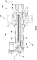
- FIG. 2 depicts a top cross section representation of the actuator 100 in a retracted condition.
- the retracted condition corresponds to a mold open condition.
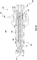
- FIG. 3A depicts a side cross section view of the actuator 100 and the clamp 140 of FIG. 2 .
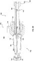
- FIG. 3B depicts a side cross section view of the actuator 100 and the clamp 140 of FIG. 2 , the actuator 100 being in an extended condition.
- the actuator 100 includes a linear actuator 102 configured to move the payload 160 relative to the support structure 170.
- the linear actuator 102 includes a drive unit 114 including an electric motor. However, other means for driving the actuator are also contemplated such as, for example, a hydraulic circuit, etc.
- the actuator 100 further includes a first compensator 104 and a second compensator 106.
- the first compensator 104 is configured to compensate for a relative misalignment between the linear actuator 102 and the payload 160.
- the first compensator 104 connects the linear actuator 102 to the payload 160.
- the second compensator 106 is configured to compensate for a relative misalignment between the linear actuator 102 and the support structure 170.
- the second compensator 106 connects the linear actuator 102 to the support structure 170.
- the linear actuator 102 further includes a threaded member 108 and a threaded collar 110 engaged with the threaded member 108.
- the threaded member 108 is configured rotate about an operational axis A1.
- the drive unit 114 is configured to rotate the threaded member 108 about the operational axis A1.
- the threaded collar 110 is configured to engage with the threaded member 108, such that the threaded member 108 causes the threaded collar 110 to move along the operational axis A1 with rotation of the threaded member 108.
- the linear actuator 102 is a ball screw type linear actuator.
- the linear actuator 102 further includes a hollow member 112 extending from the threaded collar 110 along the operational axis A1.
- the hollow member 112 is at least partially located within the clamp column 142.
- the first compensator 104 connects together the hollow member 112 and the clamp column 142.
- threaded member 108 is at least partially located within the hollow member 112.
- the support structure 170 further includes a housing 116.
- the housing 116 extends between the clamp cylinder 144 and the drive unit 114.
- the linear actuator 102 is at least partially located within the housing 116.
- the second compensator 106 connects together the housing 116 and the drive unit 114.
- the first compensator 104 includes a first joint (not separately numbered).
- the first joint pivotally connects together the payload 160 and the linear actuator 102.
- the second compensator 106 includes a second joint (not separately numbered). The second joint pivotally connects together the support structure 170 and the linear actuator 102.
- FIG. 4 depicts a partial perspective view of an actuator 200 according to a non-limiting embodiment.
- the actuator 200 includes a first compensator 204 configured to compensate for relative misalignment between the linear actuator 202 and the payload 160.
- the actuator 200 further includes a second compensator 206 configured to compensate for relative misalignment between the linear actuator 202 and the support structure 170.
- the actuator 200 is substantially the same as the non-limiting embodiment depicted in FIG. 3B , but the first compensator 204 includes a first universal joint (not separately numbered), and the second compensator 206 includes a second universal joint (not separately numbered).
- At least one of the first compensator and the second compensator may include a bendable connector.
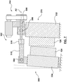
- FIG. 5 depicts a schematic representation of the actuator 100, in use.
- the linear actuator 102 includes the drive unit 114, the threaded member 108, the threaded collar 110, and the hollow member 112.
- the drive unit 114 provides motive power for rotating the threaded member 108 about the operational axis A1. Therefore, the threaded collar 110 can move towards and away from the first platen 132. In turn, the threaded collar 110 can move the payload 160 towards and away from the first platen 132.
- the second platen 134 is in a mold closed position and the clamp 140 is transmitting the clamping force across the first platen 132 and the second platen 134.
- the payload 160 includes the clamp column 142, the second platen 134, and the movable mold portion 124.
- the support structure 170 includes the first platen 132, the tie bars 138, the third platen 136, the clamp 140, and the housing 116.
- misalignment of the clamping force has caused a relative pivoting movement of the linear actuator 102 and the payload 160 about the first compensator 104.
- Misalignment of the clamping force further causes a relative pivoting movement of the linear actuator 102 and a substantially stationary part (not separately numbered) of the support structure 170 about the second compensator 106.
- the substantially stationary part includes the third platen 136, the clamp 140, and the housing 116. Therefore, in use, the first compensator 104 and the second compensator 106 can prevent, at least partially, the transmission of bending stress and strain to the linear actuator 102.
Landscapes
- Engineering & Computer Science (AREA)
- Manufacturing & Machinery (AREA)
- Mechanical Engineering (AREA)
- Injection Moulding Of Plastics Or The Like (AREA)
- Moulds For Moulding Plastics Or The Like (AREA)
Claims (2)
- Formsystem (900) umfassend einen Aktuator (100, 200),
wobei das Formsystem (900) eine Klemmanordnung (130), eine Spritzeinheit (800), einen Formmassenverteiler (126) und eine Formanordnung (120) umfasst,wobei die Klemmanordnung (130) eine erste feststehende Werkzeugaufspannplatte (132), eine zweite bewegbare Werkzeugaufspannplatte (134), eine dritte feststehende Werkzeugaufspannplatte (136), Führungsstangen (138) und eine Klemme (140) umfasst,wobei der Aktuator (100, 200) einen linearen Aktuator (102, 202) umfasst, der konfiguriert ist, eine Nutzmasse (160) bezüglich einer Stützstruktur (170) zu bewegen, wobei die Ladung (160) die Klemmsäule (142), die zweite Werkzeugaufspannplatte (134) und den Formabschnitt (124) davon umfasst, und die Stützstruktur (170) die erste Werkzeugaufspannplatte (132), die Führungsstangen (138), die dritte Werkzeugaufspannplatte (136), den Klemmzylinder (144) und ein Gehäuse (116) umfasst, das sich zwischen dem Klemmzylinder (144) und einer Antriebseinheit (114) des linearen Aktuators (102, 202) erstreckt;wobei sich die zweite Werkzeugaufspannplatte (134) zwischen der ersten und der dritten Werkzeugaufspannplatte (132, 136) befindet und verschiebbar mit den sich zwischen der ersten und der dritten Platte (132, 136) erstreckenden Führungsstangen (138) verbunden ist,wobei die Klemme (140) eine Klemmsäule (142) beinhaltet, die eine hohlzylindrische Form aufweist und mit der zweiten Werkzeugaufspannplatte (134) verbunden ist, einen Klemmzylinder (144), der eine Zylinderbohrung definiert und mit der dritten Werkzeugaufspannplatte (136) verbunden ist, und einen Klemmkolben (146), der sich bewegbar innerhalb der Zylinderbohrung befindet und eine Kolbenbohrung zur verschiebbaren Aufnahme der Klemmsäule (142) definiert, wobei der Klemmkolben (146) und die Klemmsäule (142) konfiguriert sind, zusammenzuwirken, um die Bewegung der Klemmsäule (142) zu blockieren und eine Klemmkraft aufzubringen, und diese Klemmkraft bei Verwendung die zweite Werkzeugaufspannplatte (134) in Richtung der ersten Werkzeugaufspannplatte (132) drückt und die Führungsstangen (138) zu der dritten Werkzeugaufspannplatte (136) zieht, sodass die Klemmkraft über die erste und zweite Werkzeugaufspannplatte (132, 134) ausgeübt wird, und die Einspritzeinheit (800) konfiguriert ist, unter Druck eine Formmasse einzuspritzen, und der Formmassenverteiler (126) konfiguriert ist, die Formmasse aufzunehmen und sie in einen Formhohlraum (123) der Formanordnung (120) zu verteilen, der durch einen feststehenden Formabschnitt (122) der ersten Werkzeugaufspannplatte (132) und einen bewegbaren Formabschnitt (124) der zweiten Werkzeugaufspannplatte (134) bereitgestellt wird;wobei sich der lineare Aktuator (102, 202) zumindest teilweise in dem Gehäuse (116) befindet und ein Gewindeelement (108), einen Gewindebund (110) und ein hohles Element (112) umfasst,wobei das Gewindeelement (108) konfiguriert ist, sich um eine Arbeitsachse (A1) zu drehen, und die Antriebseinheit (114) konfiguriert ist, das Gewindeelement (108) um die Arbeitsachse (A1) zu drehen,wobei der Gewindebund (110) konfiguriert ist, mit dem Gewindeelement (108) in Eingriff zu kommen, sodass das Gewindeelement (108) bewirkt, dass sich der Gewindebund (110) mit Drehung des Gewindeelements (108) entlang der Arbeitsachse (A1) bewegt, undsich das hohle Element (112) von dem Gewindebund (110) entlang der Arbeitsachse (A1) erstreckt und sich zumindest teilweise innerhalb der Klemmsäule (142) befindet, und, wenn sich der lineare Aktuator (102, 202) in einem eingefahrenen Zustand befindet, sich das Gewindeelement (108) zumindest teilweise innerhalb des hohlen Elements (112) befindet;wobei der Aktuator (100, 200) ferner einen ersten Kompensator (104, 204) zum Kompensieren einer relativen Fehlausrichtung zwischen dem linearen Aktuator (102, 202) und der Nutzmasse (160) und einen zweiten Kompensator (106, 206) zum Kompensieren einer relativen Fehlausrichtung zwischen dem lineare Aktuator (102, 202) und der Stützstruktur (170) umfasst,wobei der erste Kompensator (104, 204) ein erstes Gelenk beinhaltet, das das hohle Element (112) und die Klemmsäule (142) schwenkbar miteinander verbindet, undder zweite Kompensator (106, 206) ein zweites Gelenk beinhaltet, das das Gehäuse (116) und die Antriebseinheit (114) schwenkbar miteinander verbindet. - Formsystem (900) nach Anspruch 1, wobei das erste Gelenk des ersten Kompensators (204) ein erstes Kreuzgelenk und das zweite Gelenk des zweiten Kompensators (206) ein zweites Kreuzgelenk ist.
Applications Claiming Priority (2)
| Application Number | Priority Date | Filing Date | Title |
|---|---|---|---|
| US201361766204P | 2013-02-19 | 2013-02-19 | |
| PCT/CA2014/050039 WO2014127469A1 (en) | 2013-02-19 | 2014-01-21 | An actuator for a molding system |
Publications (4)
| Publication Number | Publication Date |
|---|---|
| EP2958729A1 EP2958729A1 (de) | 2015-12-30 |
| EP2958729A4 EP2958729A4 (de) | 2017-02-22 |
| EP2958729B1 true EP2958729B1 (de) | 2018-05-16 |
| EP2958729B8 EP2958729B8 (de) | 2018-07-04 |
Family
ID=51390440
Family Applications (1)
| Application Number | Title | Priority Date | Filing Date |
|---|---|---|---|
| EP14754918.2A Active EP2958729B8 (de) | 2013-02-19 | 2014-01-21 | Formsystem umfassend einen aktuator |
Country Status (6)
| Country | Link |
|---|---|
| US (1) | US10040233B2 (de) |
| EP (1) | EP2958729B8 (de) |
| JP (1) | JP6140843B2 (de) |
| CN (1) | CN105050793A (de) |
| CA (1) | CA2899526C (de) |
| WO (1) | WO2014127469A1 (de) |
Families Citing this family (3)
| Publication number | Priority date | Publication date | Assignee | Title |
|---|---|---|---|---|
| DE102018209700A1 (de) * | 2018-06-15 | 2019-12-19 | Skf Motion Technologies Ab | Baueinheit |
| CN113165043B (zh) * | 2018-07-24 | 2024-02-13 | 佳能弗吉尼亚股份有限公司 | 用于一起滑动的不同结构的连接 |
| DE102024127300A1 (de) * | 2024-09-20 | 2026-03-26 | Sitema Gmbh & Co. Kg | Vorrichtung zum Schließen und Klemmen einer Form oder Presse |
Family Cites Families (26)
| Publication number | Priority date | Publication date | Assignee | Title |
|---|---|---|---|---|
| JPS4834474Y1 (de) * | 1970-10-02 | 1973-10-18 | ||
| JPS62172805U (de) * | 1986-03-31 | 1987-11-02 | ||
| DE3722340A1 (de) * | 1987-07-07 | 1989-01-19 | Battenfeld Fischer Blasform | Schliessvorrichtung fuer formen zum herstellen von gegenstaenden aus thermoplastischem kunststoff |
| EP0504580A3 (en) | 1991-03-20 | 1993-02-03 | H.A. Schlatter Ag | Press device and flash butt-welding machine equipped with such a device |
| JPH07121543B2 (ja) * | 1991-09-12 | 1995-12-25 | エンゲル・マシネンバウ・ゲゼルシャフト・ミット・ベシュレンクテル・ハフツング | 射出成形機 |
| US5249951A (en) | 1991-10-25 | 1993-10-05 | Engel Maschinenbau Gesellschaft M.B.H. | Injection molding machine having tiltable mounting plates |
| US5888560A (en) | 1994-10-14 | 1999-03-30 | Engel Maschinenbau Gesellschaft M.B.H. | Injection molding machine with C-shaped frame |
| JPH0911276A (ja) * | 1995-06-27 | 1997-01-14 | Toshiba Mach Co Ltd | 射出成形機の射出ユニット旋回装置 |
| JP3510009B2 (ja) * | 1995-07-24 | 2004-03-22 | 東芝機械株式会社 | 射出成形機の型締装置 |
| DE19609568C2 (de) | 1996-03-12 | 2000-06-21 | Krauss Maffei Kunststofftech | Druckausgleichsvorrichtung zur Kompensation von Verkantungen |
| EP0956187B1 (de) | 1997-05-16 | 2002-10-02 | Milacron Inc. | Stösselträger für eine spritzgiessmaschine |
| US5922370A (en) | 1997-08-06 | 1999-07-13 | Ziv-Av; Amir | Clamping assembly for injection molding apparatus |
| US6093361A (en) * | 1998-07-31 | 2000-07-25 | Husky Injection Molding Systems Ltd. | Clamp system and method |
| JP3858238B2 (ja) * | 2000-03-06 | 2006-12-13 | 住友重機械工業株式会社 | 射出装置 |
| US6345975B1 (en) * | 2000-04-19 | 2002-02-12 | Hwa Chin Machinery Factory Co., Ltd. | Arm structure for an injecting molding machine |
| CN1489519A (zh) * | 2001-01-30 | 2004-04-14 | �е����� | 用于打开和关闭模具以及在模具上施加封闭力的直线驱动装置 |
| JP2002327826A (ja) * | 2001-04-27 | 2002-11-15 | Mitsubishi Heavy Ind Ltd | ボールねじ装置及び射出成形機の電動型開閉装置 |
| TW587542U (en) * | 2002-10-09 | 2004-05-11 | Ind Tech Res Inst | Apparatus for detecting force of extruding screw rod of injection molding machine |
| JP4017539B2 (ja) | 2003-02-24 | 2007-12-05 | トヨタ自動車株式会社 | 成形機および成形方法 |
| DE10337785B3 (de) * | 2003-08-14 | 2004-11-04 | Demag Ergotech Gmbh | Düsenanpressvorrichtung |
| JP4546268B2 (ja) * | 2004-01-30 | 2010-09-15 | 東芝機械株式会社 | 移動金型の支持装置及び型締装置 |
| DE102004032521A1 (de) | 2004-07-06 | 2006-02-16 | Demag Ergotech Gmbh | Formschließeinheit |
| AT504768B1 (de) * | 2007-02-13 | 2008-09-15 | Engel Austria Gmbh | Schliesseinheit für eine spritzgiessmaschine |
| US7628605B2 (en) * | 2007-07-20 | 2009-12-08 | Husky Injection Molding Systems Ltd. | Mold stack |
| CN102582045A (zh) * | 2011-01-17 | 2012-07-18 | 三菱重工塑胶科技有限公司 | 注塑成型机的合模装置 |
| CN104023935B (zh) | 2012-01-31 | 2016-10-19 | 三菱重工塑胶科技股份有限公司 | 合模装置及注塑成型机 |
-
2014
- 2014-01-21 JP JP2015558311A patent/JP6140843B2/ja active Active
- 2014-01-21 US US14/763,981 patent/US10040233B2/en active Active
- 2014-01-21 EP EP14754918.2A patent/EP2958729B8/de active Active
- 2014-01-21 WO PCT/CA2014/050039 patent/WO2014127469A1/en not_active Ceased
- 2014-01-21 CN CN201480016618.5A patent/CN105050793A/zh active Pending
- 2014-01-21 CA CA2899526A patent/CA2899526C/en active Active
Non-Patent Citations (1)
| Title |
|---|
| None * |
Also Published As
| Publication number | Publication date |
|---|---|
| WO2014127469A1 (en) | 2014-08-28 |
| US10040233B2 (en) | 2018-08-07 |
| EP2958729A4 (de) | 2017-02-22 |
| CA2899526C (en) | 2017-08-22 |
| JP2016508905A (ja) | 2016-03-24 |
| JP6140843B2 (ja) | 2017-05-31 |
| US20150367549A1 (en) | 2015-12-24 |
| CN105050793A (zh) | 2015-11-11 |
| EP2958729A1 (de) | 2015-12-30 |
| EP2958729B8 (de) | 2018-07-04 |
| CA2899526A1 (en) | 2014-08-28 |
Similar Documents
| Publication | Publication Date | Title |
|---|---|---|
| EP1726426B1 (de) | Formwerkzeugverriegelungsvorrichtung und formwerkzeugdickeneinstellungsverfahren | |
| EP2251176B1 (de) | Verfahren und Vorrichtung zur Schmelzansammlung in einem Schmelzereservoir einer Spritzgiessmaschine | |
| KR101383382B1 (ko) | 사출 성형 기계를 작동하기 위한 방법 및 시스템 | |
| EP2464503B1 (de) | Vorrichtung zur betätigung eines ejektors | |
| EP2958729B1 (de) | Formsystem umfassend einen aktuator | |
| EP3210744B1 (de) | Spritzgiessmaschine | |
| CN102632595A (zh) | 注射成型机的合模机构 | |
| CN104802380A (zh) | 成形机及其驱动方法 | |
| CN105538621A (zh) | 注射成型机 | |
| US7479005B2 (en) | Molding system having clamp actuator having actuator mount | |
| EP3023221B1 (de) | Formmaschine mit zusätzlicher ausstossunterstützungsanordnung zur anwendung von zusätzlicher ausstosskraft | |
| CN103660210A (zh) | 注射成型机的合模单元 | |
| US20150137425A1 (en) | Apparatus and method for injection molding | |
| JP7282137B2 (ja) | 成形装置 | |
| WO2012036811A1 (en) | Mold-tool system having actuator assembly including piston assembly and flexible diaphragm assembly | |
| CA2607390A1 (en) | A robor for an injection molding system | |
| WO2012173955A1 (en) | Molding system including stationary platen positioned between actuation assembly and stem-actuation plate | |
| HK1171985B (en) | Apparatus for ejector actuation |
Legal Events
| Date | Code | Title | Description |
|---|---|---|---|
| PUAI | Public reference made under article 153(3) epc to a published international application that has entered the european phase |
Free format text: ORIGINAL CODE: 0009012 |
|
| 17P | Request for examination filed |
Effective date: 20151110 |
|
| AK | Designated contracting states |
Kind code of ref document: A1 Designated state(s): AL AT BE BG CH CY CZ DE DK EE ES FI FR GB GR HR HU IE IS IT LI LT LU LV MC MK MT NL NO PL PT RO RS SE SI SK SM TR |
|
| AX | Request for extension of the european patent |
Extension state: BA ME |
|
| RAP1 | Party data changed (applicant data changed or rights of an application transferred) |
Owner name: HUSKY INJECTION MOLDING SYSTEMS LUXEMBOURG IP DEVE |
|
| DAX | Request for extension of the european patent (deleted) | ||
| REG | Reference to a national code |
Ref country code: DE Ref legal event code: R079 Ref document number: 602014025593 Country of ref document: DE Free format text: PREVIOUS MAIN CLASS: B29C0045640000 Ipc: B29C0045660000 |
|
| A4 | Supplementary search report drawn up and despatched |
Effective date: 20170123 |
|
| RIC1 | Information provided on ipc code assigned before grant |
Ipc: B29C 45/17 20060101ALI20170117BHEP Ipc: B29C 45/66 20060101AFI20170117BHEP |
|
| GRAP | Despatch of communication of intention to grant a patent |
Free format text: ORIGINAL CODE: EPIDOSNIGR1 |
|
| STAA | Information on the status of an ep patent application or granted ep patent |
Free format text: STATUS: GRANT OF PATENT IS INTENDED |
|
| INTG | Intention to grant announced |
Effective date: 20171206 |
|
| GRAS | Grant fee paid |
Free format text: ORIGINAL CODE: EPIDOSNIGR3 |
|
| GRAA | (expected) grant |
Free format text: ORIGINAL CODE: 0009210 |
|
| STAA | Information on the status of an ep patent application or granted ep patent |
Free format text: STATUS: THE PATENT HAS BEEN GRANTED |
|
| AK | Designated contracting states |
Kind code of ref document: B1 Designated state(s): AL AT BE BG CH CY CZ DE DK EE ES FI FR GB GR HR HU IE IS IT LI LT LU LV MC MK MT NL NO PL PT RO RS SE SI SK SM TR |
|
| REG | Reference to a national code |
Ref country code: GB Ref legal event code: FG4D |
|
| REG | Reference to a national code |
Ref country code: CH Ref legal event code: EP |
|
| REG | Reference to a national code |
Ref country code: DE Ref legal event code: R096 Ref document number: 602014025593 Country of ref document: DE |
|
| REG | Reference to a national code |
Ref country code: IE Ref legal event code: FG4D |
|
| REG | Reference to a national code |
Ref country code: AT Ref legal event code: REF Ref document number: 999140 Country of ref document: AT Kind code of ref document: T Effective date: 20180615 |
|
| RAP2 | Party data changed (patent owner data changed or rights of a patent transferred) |
Owner name: HUSKY INJECTION MOLDING SYSTEMS LTD. |
|
| REG | Reference to a national code |
Ref country code: NL Ref legal event code: MP Effective date: 20180516 |
|
| REG | Reference to a national code |
Ref country code: LT Ref legal event code: MG4D |
|
| PG25 | Lapsed in a contracting state [announced via postgrant information from national office to epo] |
Ref country code: SE Free format text: LAPSE BECAUSE OF FAILURE TO SUBMIT A TRANSLATION OF THE DESCRIPTION OR TO PAY THE FEE WITHIN THE PRESCRIBED TIME-LIMIT Effective date: 20180516 Ref country code: LT Free format text: LAPSE BECAUSE OF FAILURE TO SUBMIT A TRANSLATION OF THE DESCRIPTION OR TO PAY THE FEE WITHIN THE PRESCRIBED TIME-LIMIT Effective date: 20180516 Ref country code: ES Free format text: LAPSE BECAUSE OF FAILURE TO SUBMIT A TRANSLATION OF THE DESCRIPTION OR TO PAY THE FEE WITHIN THE PRESCRIBED TIME-LIMIT Effective date: 20180516 Ref country code: FI Free format text: LAPSE BECAUSE OF FAILURE TO SUBMIT A TRANSLATION OF THE DESCRIPTION OR TO PAY THE FEE WITHIN THE PRESCRIBED TIME-LIMIT Effective date: 20180516 Ref country code: BG Free format text: LAPSE BECAUSE OF FAILURE TO SUBMIT A TRANSLATION OF THE DESCRIPTION OR TO PAY THE FEE WITHIN THE PRESCRIBED TIME-LIMIT Effective date: 20180816 Ref country code: NO Free format text: LAPSE BECAUSE OF FAILURE TO SUBMIT A TRANSLATION OF THE DESCRIPTION OR TO PAY THE FEE WITHIN THE PRESCRIBED TIME-LIMIT Effective date: 20180816 |
|
| PG25 | Lapsed in a contracting state [announced via postgrant information from national office to epo] |
Ref country code: GR Free format text: LAPSE BECAUSE OF FAILURE TO SUBMIT A TRANSLATION OF THE DESCRIPTION OR TO PAY THE FEE WITHIN THE PRESCRIBED TIME-LIMIT Effective date: 20180817 Ref country code: LV Free format text: LAPSE BECAUSE OF FAILURE TO SUBMIT A TRANSLATION OF THE DESCRIPTION OR TO PAY THE FEE WITHIN THE PRESCRIBED TIME-LIMIT Effective date: 20180516 Ref country code: NL Free format text: LAPSE BECAUSE OF FAILURE TO SUBMIT A TRANSLATION OF THE DESCRIPTION OR TO PAY THE FEE WITHIN THE PRESCRIBED TIME-LIMIT Effective date: 20180516 Ref country code: RS Free format text: LAPSE BECAUSE OF FAILURE TO SUBMIT A TRANSLATION OF THE DESCRIPTION OR TO PAY THE FEE WITHIN THE PRESCRIBED TIME-LIMIT Effective date: 20180516 Ref country code: HR Free format text: LAPSE BECAUSE OF FAILURE TO SUBMIT A TRANSLATION OF THE DESCRIPTION OR TO PAY THE FEE WITHIN THE PRESCRIBED TIME-LIMIT Effective date: 20180516 |
|
| REG | Reference to a national code |
Ref country code: AT Ref legal event code: MK05 Ref document number: 999140 Country of ref document: AT Kind code of ref document: T Effective date: 20180516 |
|
| PG25 | Lapsed in a contracting state [announced via postgrant information from national office to epo] |
Ref country code: CZ Free format text: LAPSE BECAUSE OF FAILURE TO SUBMIT A TRANSLATION OF THE DESCRIPTION OR TO PAY THE FEE WITHIN THE PRESCRIBED TIME-LIMIT Effective date: 20180516 Ref country code: PL Free format text: LAPSE BECAUSE OF FAILURE TO SUBMIT A TRANSLATION OF THE DESCRIPTION OR TO PAY THE FEE WITHIN THE PRESCRIBED TIME-LIMIT Effective date: 20180516 Ref country code: SK Free format text: LAPSE BECAUSE OF FAILURE TO SUBMIT A TRANSLATION OF THE DESCRIPTION OR TO PAY THE FEE WITHIN THE PRESCRIBED TIME-LIMIT Effective date: 20180516 Ref country code: RO Free format text: LAPSE BECAUSE OF FAILURE TO SUBMIT A TRANSLATION OF THE DESCRIPTION OR TO PAY THE FEE WITHIN THE PRESCRIBED TIME-LIMIT Effective date: 20180516 Ref country code: DK Free format text: LAPSE BECAUSE OF FAILURE TO SUBMIT A TRANSLATION OF THE DESCRIPTION OR TO PAY THE FEE WITHIN THE PRESCRIBED TIME-LIMIT Effective date: 20180516 Ref country code: AT Free format text: LAPSE BECAUSE OF FAILURE TO SUBMIT A TRANSLATION OF THE DESCRIPTION OR TO PAY THE FEE WITHIN THE PRESCRIBED TIME-LIMIT Effective date: 20180516 Ref country code: EE Free format text: LAPSE BECAUSE OF FAILURE TO SUBMIT A TRANSLATION OF THE DESCRIPTION OR TO PAY THE FEE WITHIN THE PRESCRIBED TIME-LIMIT Effective date: 20180516 |
|
| REG | Reference to a national code |
Ref country code: DE Ref legal event code: R097 Ref document number: 602014025593 Country of ref document: DE |
|
| PG25 | Lapsed in a contracting state [announced via postgrant information from national office to epo] |
Ref country code: SM Free format text: LAPSE BECAUSE OF FAILURE TO SUBMIT A TRANSLATION OF THE DESCRIPTION OR TO PAY THE FEE WITHIN THE PRESCRIBED TIME-LIMIT Effective date: 20180516 Ref country code: IT Free format text: LAPSE BECAUSE OF FAILURE TO SUBMIT A TRANSLATION OF THE DESCRIPTION OR TO PAY THE FEE WITHIN THE PRESCRIBED TIME-LIMIT Effective date: 20180516 |
|
| PLBE | No opposition filed within time limit |
Free format text: ORIGINAL CODE: 0009261 |
|
| STAA | Information on the status of an ep patent application or granted ep patent |
Free format text: STATUS: NO OPPOSITION FILED WITHIN TIME LIMIT |
|
| 26N | No opposition filed |
Effective date: 20190219 |
|
| PG25 | Lapsed in a contracting state [announced via postgrant information from national office to epo] |
Ref country code: SI Free format text: LAPSE BECAUSE OF FAILURE TO SUBMIT A TRANSLATION OF THE DESCRIPTION OR TO PAY THE FEE WITHIN THE PRESCRIBED TIME-LIMIT Effective date: 20180516 |
|
| PG25 | Lapsed in a contracting state [announced via postgrant information from national office to epo] |
Ref country code: MC Free format text: LAPSE BECAUSE OF FAILURE TO SUBMIT A TRANSLATION OF THE DESCRIPTION OR TO PAY THE FEE WITHIN THE PRESCRIBED TIME-LIMIT Effective date: 20180516 |
|
| REG | Reference to a national code |
Ref country code: BE Ref legal event code: MM Effective date: 20190131 |
|
| REG | Reference to a national code |
Ref country code: IE Ref legal event code: MM4A |
|
| PG25 | Lapsed in a contracting state [announced via postgrant information from national office to epo] |
Ref country code: AL Free format text: LAPSE BECAUSE OF FAILURE TO SUBMIT A TRANSLATION OF THE DESCRIPTION OR TO PAY THE FEE WITHIN THE PRESCRIBED TIME-LIMIT Effective date: 20180516 Ref country code: BE Free format text: LAPSE BECAUSE OF NON-PAYMENT OF DUE FEES Effective date: 20190131 |
|
| PG25 | Lapsed in a contracting state [announced via postgrant information from national office to epo] |
Ref country code: IE Free format text: LAPSE BECAUSE OF NON-PAYMENT OF DUE FEES Effective date: 20190121 |
|
| PG25 | Lapsed in a contracting state [announced via postgrant information from national office to epo] |
Ref country code: TR Free format text: LAPSE BECAUSE OF FAILURE TO SUBMIT A TRANSLATION OF THE DESCRIPTION OR TO PAY THE FEE WITHIN THE PRESCRIBED TIME-LIMIT Effective date: 20180516 |
|
| PG25 | Lapsed in a contracting state [announced via postgrant information from national office to epo] |
Ref country code: PT Free format text: LAPSE BECAUSE OF FAILURE TO SUBMIT A TRANSLATION OF THE DESCRIPTION OR TO PAY THE FEE WITHIN THE PRESCRIBED TIME-LIMIT Effective date: 20180917 Ref country code: MT Free format text: LAPSE BECAUSE OF NON-PAYMENT OF DUE FEES Effective date: 20190121 |
|
| PG25 | Lapsed in a contracting state [announced via postgrant information from national office to epo] |
Ref country code: CY Free format text: LAPSE BECAUSE OF FAILURE TO SUBMIT A TRANSLATION OF THE DESCRIPTION OR TO PAY THE FEE WITHIN THE PRESCRIBED TIME-LIMIT Effective date: 20180516 |
|
| PG25 | Lapsed in a contracting state [announced via postgrant information from national office to epo] |
Ref country code: IS Free format text: LAPSE BECAUSE OF FAILURE TO SUBMIT A TRANSLATION OF THE DESCRIPTION OR TO PAY THE FEE WITHIN THE PRESCRIBED TIME-LIMIT Effective date: 20180916 |
|
| PG25 | Lapsed in a contracting state [announced via postgrant information from national office to epo] |
Ref country code: HU Free format text: LAPSE BECAUSE OF FAILURE TO SUBMIT A TRANSLATION OF THE DESCRIPTION OR TO PAY THE FEE WITHIN THE PRESCRIBED TIME-LIMIT; INVALID AB INITIO Effective date: 20140121 |
|
| PG25 | Lapsed in a contracting state [announced via postgrant information from national office to epo] |
Ref country code: MK Free format text: LAPSE BECAUSE OF FAILURE TO SUBMIT A TRANSLATION OF THE DESCRIPTION OR TO PAY THE FEE WITHIN THE PRESCRIBED TIME-LIMIT Effective date: 20180516 |
|
| P01 | Opt-out of the competence of the unified patent court (upc) registered |
Effective date: 20230516 |
|
| PGFP | Annual fee paid to national office [announced via postgrant information from national office to epo] |
Ref country code: GB Payment date: 20251215 Year of fee payment: 13 |
|
| PGFP | Annual fee paid to national office [announced via postgrant information from national office to epo] |
Ref country code: LU Payment date: 20251215 Year of fee payment: 13 Ref country code: FR Payment date: 20251215 Year of fee payment: 13 |
|
| REG | Reference to a national code |
Ref country code: CH Ref legal event code: U11 Free format text: ST27 STATUS EVENT CODE: U-0-0-U10-U11 (AS PROVIDED BY THE NATIONAL OFFICE) Effective date: 20260201 |
|
| PGFP | Annual fee paid to national office [announced via postgrant information from national office to epo] |
Ref country code: DE Payment date: 20251212 Year of fee payment: 13 |
|
| PGFP | Annual fee paid to national office [announced via postgrant information from national office to epo] |
Ref country code: CH Payment date: 20260201 Year of fee payment: 13 |