EP2958754B1 - Procédé de réduction des effets de bandes dans l'image - Google Patents
Procédé de réduction des effets de bandes dans l'image Download PDFInfo
- Publication number
- EP2958754B1 EP2958754B1 EP15723646.4A EP15723646A EP2958754B1 EP 2958754 B1 EP2958754 B1 EP 2958754B1 EP 15723646 A EP15723646 A EP 15723646A EP 2958754 B1 EP2958754 B1 EP 2958754B1
- Authority
- EP
- European Patent Office
- Prior art keywords
- scanning
- printing
- line
- drying
- printed
- Prior art date
- Legal status (The legal status is an assumption and is not a legal conclusion. Google has not performed a legal analysis and makes no representation as to the accuracy of the status listed.)
- Active
Links
Images

Classifications
-
- B—PERFORMING OPERATIONS; TRANSPORTING
- B41—PRINTING; LINING MACHINES; TYPEWRITERS; STAMPS
- B41J—TYPEWRITERS; SELECTIVE PRINTING MECHANISMS, i.e. MECHANISMS PRINTING OTHERWISE THAN FROM A FORME; CORRECTION OF TYPOGRAPHICAL ERRORS
- B41J11/00—Devices or arrangements of selective printing mechanisms, e.g. ink-jet printers or thermal printers, for supporting or handling copy material in sheet or web form
- B41J11/0015—Devices or arrangements of selective printing mechanisms, e.g. ink-jet printers or thermal printers, for supporting or handling copy material in sheet or web form for treating before, during or after printing or for uniform coating or laminating the copy material before or after printing
- B41J11/002—Curing or drying the ink on the copy materials, e.g. by heating or irradiating
- B41J11/0021—Curing or drying the ink on the copy materials, e.g. by heating or irradiating using irradiation
- B41J11/00214—Curing or drying the ink on the copy materials, e.g. by heating or irradiating using irradiation using UV radiation
-
- B—PERFORMING OPERATIONS; TRANSPORTING
- B41—PRINTING; LINING MACHINES; TYPEWRITERS; STAMPS
- B41J—TYPEWRITERS; SELECTIVE PRINTING MECHANISMS, i.e. MECHANISMS PRINTING OTHERWISE THAN FROM A FORME; CORRECTION OF TYPOGRAPHICAL ERRORS
- B41J11/00—Devices or arrangements of selective printing mechanisms, e.g. ink-jet printers or thermal printers, for supporting or handling copy material in sheet or web form
- B41J11/0015—Devices or arrangements of selective printing mechanisms, e.g. ink-jet printers or thermal printers, for supporting or handling copy material in sheet or web form for treating before, during or after printing or for uniform coating or laminating the copy material before or after printing
-
- B—PERFORMING OPERATIONS; TRANSPORTING
- B41—PRINTING; LINING MACHINES; TYPEWRITERS; STAMPS
- B41J—TYPEWRITERS; SELECTIVE PRINTING MECHANISMS, i.e. MECHANISMS PRINTING OTHERWISE THAN FROM A FORME; CORRECTION OF TYPOGRAPHICAL ERRORS
- B41J13/00—Devices or arrangements of selective printing mechanisms, e.g. ink-jet printers or thermal printers, specially adapted for supporting or handling copy material in short lengths, e.g. sheets
- B41J13/0009—Devices or arrangements of selective printing mechanisms, e.g. ink-jet printers or thermal printers, specially adapted for supporting or handling copy material in short lengths, e.g. sheets control of the transport of the copy material
-
- B—PERFORMING OPERATIONS; TRANSPORTING
- B41—PRINTING; LINING MACHINES; TYPEWRITERS; STAMPS
- B41M—PRINTING, DUPLICATING, MARKING, OR COPYING PROCESSES; COLOUR PRINTING
- B41M5/00—Duplicating or marking methods; Sheet materials for use therein
-
- B—PERFORMING OPERATIONS; TRANSPORTING
- B41—PRINTING; LINING MACHINES; TYPEWRITERS; STAMPS
- B41M—PRINTING, DUPLICATING, MARKING, OR COPYING PROCESSES; COLOUR PRINTING
- B41M7/00—After-treatment of prints, e.g. heating, irradiating, setting of the ink, protection of the printed stock
- B41M7/0081—After-treatment of prints, e.g. heating, irradiating, setting of the ink, protection of the printed stock using electromagnetic radiation or waves, e.g. ultraviolet radiation, electron beams
-
- B—PERFORMING OPERATIONS; TRANSPORTING
- B41—PRINTING; LINING MACHINES; TYPEWRITERS; STAMPS
- B41M—PRINTING, DUPLICATING, MARKING, OR COPYING PROCESSES; COLOUR PRINTING
- B41M7/00—After-treatment of prints, e.g. heating, irradiating, setting of the ink, protection of the printed stock
- B41M7/009—After-treatment of prints, e.g. heating, irradiating, setting of the ink, protection of the printed stock using thermal means, e.g. infrared radiation, heat
Definitions
- the present invention relates to a method of reducing disadvantageous banding effects, particularly glossy banding effects, in printed images made with an ink jet printer.
- the invention additionally relates to an ink jet printer comprising a control device for carrying out such a method.
- Banding effects are known to be noticeable impairments in the quality of an image and are characterized by the fact that in the printed image, abrupt or continuous transitions of image attributes, such as gloss or color, become visibly and unpleasantly noticeable, where no transitions of this kind are desired ,
- the causes of such transitions can be of a variety of nature and in certain cases can be concretely assigned to specific quality parameters such as the inhomogeneity of the drop shape or the inhomogeneity of the ink application or the inhomogeneity of the drop placement, but in other cases are subject to the interaction of several quality parameters.
- the droplet shape of the ink droplets that can be realized on a medium is not exactly circular, but that it is dependent on the printing direction, among other things.
- the pressure-direction-dependent drop shape is most pronounced immediately after impinging on the medium and may at least partially lose its pressure-direction-dependent character over time due to the wetting behavior of the ink drops.
- the pressure-direction-dependent droplet shape of the ink droplets is due to their trajectory, so that in a scanning process, for example, the impact of ink drops on the medium results in an approximately ellipsenfömige in the printing direction and approximately wedge-shaped in height drop shape whose tapered side facing the printing direction.
- a singlescan method is understood as meaning, for example, a method in which a scanning printing module comprising at least one print head travels only once, ie in a single pass over a line of a medium to be printed during which this line is printed such that in the course of a scan movement of a single sweep the line is finished printing.
- a print module including at least one printhead in a first passport passes in a scan direction only once over a line during which it is being printed. Upon reaching the end of the line, the medium to be printed is shifted by one line width in the feed direction of the medium. In a second printing pass, the printing module moves in a direction opposite to the first scanning direction of the second scanning direction over another line during which this is printed. Subsequently, the medium to be printed is shifted by a further line width in the feed direction of the medium. For printing further lines can be proceeded in an analogous manner to the above steps.
- the banding effect (also called banding effect) is particularly pronounced, since the lines printed in opposite directions in turn have drops with contra-approximately wedge-shaped drop shapes, which from a perspective reflect the light differently, so that gloss transitions between appear abrupt on the adjacent lines.
- the determination of the time interval between printing and drying is usually decisive for the desired degree of gloss or mattness of an image or a partial region of an image, since the time interval predetermines, inter alia, whether and to what extent the ink droplets can wet the surface of the medium.
- ink drops are completely dried or hardened immediately after printing, they do not have time to diverge or contract (depending on the wetting behavior: no wetting, partial wetting, complete wetting), so that such a procedure causes the image to appear dull or grainy.
- banding effects appear as abrupt gloss transitions between adjacent and counter-printed lines, but they can also occur in one and the same line as continuous gloss transitions.
- ink drops are ejected from the print module in a print pass when scanning the print module from a starting point to an end point of a line and the printed ink droplets are not completely cured immediately after striking the medium, but only in one the second printing pass opposite to the first printing pass, in which the printing module is moved from the end position to the starting position of the same line and the ink drops printed in the preceding printing pass are hardened with a drying or hardening unit.
- the maintenance of constant time intervals for the minimization of continuous gloss banding effects is technically easy to accomplish, for example by arranging a drying or curing unit downstream of a printing module in the feed direction of the medium, so that for each position of the medium, the same time interval between printing and drying or curing can be maintained.
- a single-pass printer is understood to mean a printer in which the medium is continuously moved in an operating mode and a print head sees the medium only once, the print heads not being operated according to the known scanning method, but arranged substantially stationary.
- banding effects due to the inhomogeneity of the drop shape can be reduced in part by using a printing module several times over the same line from more than one direction (eg bidirectional), so that the structure one line of the image is made stepwise, such that the ink drops are nested according to a particular Rechenalgorythmus applied.
- the ink drops can vary depending on desired gloss effect be dried immediately or not immediately after printing.
- banding effects can also occur due to the inhomogeneity of the drop placement.
- the inhomogeneity of the drop placement may, for example, be due to inaccurate media routing and / or print module routing, and / or may be due to the drying or curing steps that have been performed.
- An inhomogeneity of the drop placement that occurs as a result of drying or hardening steps can occur in heat-sensitive media, for example if a multiscan method is used, whereby one and the same point of a line of the medium to be printed undergoes several printing steps and is subjected to several drying or hardening steps.
- the print module travels from a starting position to an end position in a first print pass, for example, with a UV light generating mercury lamp as a drying or curing unit running upstream in the scan direction becomes during which printing is carried out and the printed drops are cured immediately after printing with the drying or hardening unit, the medium is exposed to the waste heat of the drying or hardening unit.
- a UV light generating mercury lamp as a drying or curing unit running upstream in the scan direction becomes during which printing is carried out and the printed drops are cured immediately after printing with the drying or hardening unit, the medium is exposed to the waste heat of the drying or hardening unit.
- the medium can shrink, for example when it contains a solvent or water and at least partially evaporates due to the heating. If the print module moves back to the starting position in a second print pass, the ink drops can no longer be printed to the intended positions.
- the exact media guidance and / or carriage guidance is very important for the precision of the drop placement, since even a certain overlap of the printed lines at their edge regions can, for example, cause banding by a double ink application.
- inhomogeneity of the drop placement may occur, for example, when dried or liquid ink residues are present in the nozzle opening environment of a printhead of a print module, so that affected nozzle openings could be at least partially closed and these ink residues are in the way of the trajectory of the ink drops, so that the ejection process is disturbed.
- the ink drops can no longer impinge on the desired positions of the medium to be printed. If dried ink residues are present in the nozzle opening environment, the affected nozzle can become a skewed jet or the nozzle can fail completely.
- the inhomogeneity of the drop placement can result in an inhomogeneity of the ink application, as indicated above, which in turn causes a color banding effect causes.
- the inhomogeneity of the ink application may also be nozzle specific due to a not exactly identical design of the nozzle, which does not exactly identical design causes an ejection of unwanted differently sized drops.
- the present invention has for its object to provide a method for a printer, with which said banding effects can be at least partially reduced, so that the quality of the image can be increased.
- the procedure is now such that the banding effects in images, in particular the gloss banding effects, can be at least partially reduced by providing a method in which lines of line width B printed with a scanning print module are provided, their line-edge forming ends define a printing texture and are provided with a scanning drying or curing unit substantially completely cured lines of line width H whose line edge forming ends define a wet / dry texture, wherein a printed line of a print scan and a hardened line of a cure scan overlapping but not congruent.
- drying / curing means that the printed drops of ink are substantially completely dried or cured.
- the term "scan” is understood to mean the departure of a specific scanning path with the printing module or with the drying or curing unit.
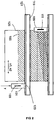
- FIG. 1 shows an image produced with a preferred embodiment of the inventive method.
- the picture shows a printer which operates with a scanning printing module 101, a scanning drying unit 109 and a media feed.
- a scanning printing module 101 printed lines 105 of line width B were provided, whose line edge forming ends define a printing texture 107, and with a scanning curing unit 109 were substantially completely cured lines 115 forming one line -Width H may provide whose line edge forming ends define a wet / dry texture 117.
- the printing module 101 is guided by means of a linear guide system 119, which linear guide system 119 has a guide rail 121 and at least one movable guide module 101 provided with guide elements 123 in the running direction of the guide rail 121.
- essentially completely dried or hardened lines 107 which may have a line width H, are provided whose line edge forming ends define a wet / dry texture 117.
- the first cured line has a different line width than the line H line 115 provided in the second cure pass.
- a printed line 105 of a print scan and a hardened line 115 of a cure scan are overlapping but not formed congruent.
- a printer operates with a scanning printing module 101, a scanning drying or curing unit 109 and a media feed, wherein lines 105 printed with the scanning printing module 101 are provided with line width B whose line edge forming ends define a printing texture 107 and are provided with a scanning drying or curing unit 109 substantially completely cured lines 115 of line width H, the ends of which forming a line edge Wet / dry texture 117 define.
- a printed line 105 of a print scan and a hardened line 115 of a curing scan are formed overlapping but not congruent.
- the printing texture 107 can be designed to run parallel with respect to the scanning direction of the printing module 101 and the wet / dry texture 117 can be designed to run parallel or not parallel with respect to the printing texture 107.
- a wet / dry texture 117 which has been made parallel with respect to the pressure texture 107 is, for example, in FIG. 1 shown.
- the drying or hardening unit 109 can dry or harden simultaneously in an active passage (hardening pass) from the one side to the other side printed drops, which in the context of at least two different active Passes (print pass) of the print module 101 are printed. There are therefore in the context of a passage of the printing module 101 printed drops which are dried or cured in the context of different passes of the drying or curing unit 109.
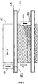
- FIG. 2 shows a printed image with a wet / dry texture 117 which, for example, was not formed parallel to the print texture 107 and does not intersect the print texture 107.
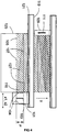
- the wet / dry texture 117 which is non-parallel with respect to the pressure texture 107, may in one preferred embodiment of the invention cross one or more printed textures 107. Such an example will be in FIG. 3 in which a wet / dry texture 117 has been provided that intersects at least one print texture 107.
- At least one second wet / dry texture 117 is formed with the scanning drying or curing unit 109, which is formed to extend parallel or not parallel with respect to the first wet / dry texture 117.
- the scanning drying or curing unit 109 can be spaced apart from the scanning printing module 101 and can be moved downstream in the direction of advance of the medium. This is particularly advantageous when heat-sensitive media 125 are used since they are not printed in the immediate vicinity of the area of action of the drying or curing unit 101.
- the drying or hardening unit 109 may comprise at least one UV diode arrangement or at least one UV lamp 111, with which the drying or curing takes place.
- the speed of movement of the scanning drying or curing unit 109 can be kept constant or variable at least during the drying or hardening.
- the scanning speed of the drying or curing device 109 and the feed rate of the medium 125 during drying or hardening of a printed line 105 may at least temporarily be greater than zero at the same time.
- a time interval between printing and drying for different printed locations of the medium 125 is selected such that it is kept approximately constant or not constant.
- the UV diode array or the UV lamp may comprise a plurality of radiation sources, which are controlled independently of each other.
- the printer can operate with a scanning printing module 101 comprising at least one pinning device 104 with at least one UV LED arrangement, which at least one pinning device 104 respectively at the opposite in the scan direction ends of the print module 101st wherein printed lines 105 of line width B are provided with the scanning printing module 101, whose line edge forming ends define a printing texture 107 and immediately after which lines P 116 of line width P are provided in the same print scan whose line-edge-forming ends define a pinning texture 127, wherein a printed line 105 of a print scan and a pinned line 116 of a pining scan are formed overlapping but not congruent.
- the printed lines 105 and / or the hardened lines 115 and / or the pinned lines 116 may each have constant or variable widths.
- FIG. 4 An image prepared according to this preferred embodiment is shown in FIG. 4 in which the pinned lines 116 have a variable line width P at different locations along the scanning direction X1.
- the printer comprises a scanning printing module 101 and a positioning device which is designed to be able to move a medium 125 in a feed direction and the scanning printing module 101 in a scanning direction perpendicular to the feed direction, the printing module 101 having at least one print head 103 with at least one Nozzle row and the ink jet printer comprises a scanning drying or curing unit 109, wherein the printer comprises a control unit for performing at least one inventive method.
- the drying or hardening unit 109 can be arranged downstream of the scanning printing module 101 in the feed direction of the medium 125.
- the printer may be an inkjet printer.
Landscapes
- Health & Medical Sciences (AREA)
- General Health & Medical Sciences (AREA)
- Toxicology (AREA)
- Ink Jet (AREA)
- Printing Methods (AREA)
Claims (15)
- Méthode de réduction des effets de bande dans des images, en particulier des effets de bandes de brillance, au moyen d'une imprimante qui travaille avec un module d'impression à balayage (101), une unité de séchage ou de durcissement à balayage (109), et un avancement du support, le module d'impression à balayage (101) fournissant des lignes imprimées (105) ayant une largeur de ligne B dont les extrémités qui forment la bordure de ligne définissent une texture d'impression (107), et une unité de séchage ou de durcissement à balayage (109) fournissant essentiellement des lignes complètement séchées ou durcies (115) ayant une largeur de ligne H dont les extrémités qui forment la bordure de ligne définissent une texture humide/sèche (117) caractérisée par le fait que la ligne imprimée (105) d'un balayage d'impression, et la ligne durcie (115) d'un balayage de durcissement sont formées de manière à se chevaucher, mais toutefois sans coïncider.
- Méthode selon la revendication 1 caractérisée par le fait que la texture d'impression (107) est conçue de manière à s'étendre parallèlement par rapport à la direction de balayage du module d'impression (101) et la texture humide/sèche (117) est conçue de manière à s'étendre parallèlement ou non parallèlement par rapport à la texture d'impression (107).
- Méthode selon la revendication 2 caractérisée par le fait que la texture humide/sèche (117) qui est conçue de manière à s'étendre non parallèlement par rapport à la texture d'impression (107) croise une ou plusieurs textures d'impression (107).
- Méthode selon une des revendications précédentes caractérisée par le fait que, en étant espacée du module d'impression à balayage (101) et en étant placée en aval dans la direction d'avancement du support (125), l'unité de séchage ou de durcissement à balayage (109) est déplacée en mode de balayage.
- Méthode selon du moins une des revendications précédentes caractérisée par le fait que l'unité de séchage ou de durcissement (109) comprend du moins un réseau de diodes UV ou du moins une lampe UV (111) à l'aide duquel / de laquelle le séchage ou le durcissement s'effectue.
- Méthode selon du moins une des revendications précédentes caractérisée par le fait que la vitesse de déplacement de l'unité de séchage ou de durcissement à balayage (109) est maintenue constante ou variable pour un certain temps du moins pendant le séchage ou le durcissement.
- Méthode selon du moins une des revendications précédentes caractérisée par le fait que la vitesse de balayage de l'unité de séchage ou de durcissement (109) et la vitesse d'avancement du support (125) sont du moins pour un certain temps simultanément supérieures à zero pendant le séchage ou le durcissement d'une ligne imprimée (115).
- Méthode selon du moins une des revendications précédentes caractérisée par le fait qu'un intervalle de temps entre l'impression et le séchage pour différents endroits imprimés du support (125) est choisi de manière que celui-ci soit maintenu approximativement constant ou non constant.
- Méthode selon la revendication 5 ou selon la revendication 5 et du moins une des revendications 6 à 8 caractérisée par le fait que le réseau de diode UV ou la lampe UV (111) comprend plusieurs sources de rayonnement qui sont commandés indépendamment l'une de l'autre.
- Méthode selon du moins une des revendications précédentes caractérisée par le fait que l'imprimante travaille avec un module d'impression à balayage (101) comprenant du moins une installation de pinning (104) ayant du moins un réseau de LED-UV quelle du moins une installation de pinning (104) est disposée respectivement aux extrémités du module d'impression(101) opposées à la direction de balayage, le module d'impression à balayage (101) fournissant des lignes imprimées (105) ayant une largeur de ligne B dont les extrémités formant la bordure de ligne définissent une texture d'impression (107) et immédiatement après dans le même balayage d'impression des lignes partiellement séchées ou durcies ayant une largeur de ligne P étant fournies dont les extrémités formant la bordure de ligne définissent une texture de pinning (127), une lignée imprimée (105) d'un balayage d'impression et une ligne partiellement séchée ou durcie (116) d'un balayage de pinning étant conçues de façon à se chevaucher, mais toutefois sans coïncider.
- Méthode selon du moins une des revendications précédentes caractérisée par le fait que par l'unité de séchage ou de durcissement à balayage (109) du moins une seconde texture humide/sèche (117) est formée qui par rapport à la première texture humide/sèche (117) est conçue de façon à s'étendre parallèlement ou non parallèlement.
- Méthode selon du moins une des revendications précédentes caractérisée par le fait que les lignes imprimées (105) et/ou les lignes durcies (115) et/ou les lignes sechées ou durcies partiellement (116) ont chacunes des largeurs constants ou variables B, H, P.
- Méthode selon du moins une des revendications précédentes caractérisée par le fait que l'imprimante est une imprimante à jet d'encre.
- Imprimante à jet d'encre comprenant un module d'impression à balayage (101) et un dispositif de positionnement qui est destiné à pouvoir déplacer le support (125) dans une direction d'avancement et le module d'impression à balayage (101) dans une direction de balayage perpendiculaire à la direction d'avancement, le module d'impression (101) comprenant au moins une tête d'impression (103) dotée d'au moins une rangée de buses et l'imprimante à jet d'encre comprenant une unité de séchage ou de durcissement à balayage (109) caractérisé par le fait que l'imprimante à jet d'encre comprend une unité de contrôle pour réaliser un procédé selon une des revendications 1 - 13.
- Imprimante à jet d'encre selon la revendication 14 caractérisée par le fait que l'unité de sèchage ou de durcissement (109) est disposée en aval dans la direction d'avancement du support (125) en partant du module d'impression à balayage (101).
Applications Claiming Priority (2)
| Application Number | Priority Date | Filing Date | Title |
|---|---|---|---|
| DE102014007131.6A DE102014007131A1 (de) | 2014-05-16 | 2014-05-16 | Verfahren zur Reduktion von Banding-Effekten |
| PCT/EP2015/000904 WO2015172867A1 (fr) | 2014-05-16 | 2015-05-04 | Procédé de réduction des effets de bandes dans l'image |
Publications (2)
| Publication Number | Publication Date |
|---|---|
| EP2958754A1 EP2958754A1 (fr) | 2015-12-30 |
| EP2958754B1 true EP2958754B1 (fr) | 2017-08-02 |
Family
ID=53191634
Family Applications (1)
| Application Number | Title | Priority Date | Filing Date |
|---|---|---|---|
| EP15723646.4A Active EP2958754B1 (fr) | 2014-05-16 | 2015-05-04 | Procédé de réduction des effets de bandes dans l'image |
Country Status (6)
| Country | Link |
|---|---|
| US (1) | US10166792B2 (fr) |
| EP (1) | EP2958754B1 (fr) |
| DE (1) | DE102014007131A1 (fr) |
| ES (1) | ES2645939T3 (fr) |
| MX (1) | MX365895B (fr) |
| WO (1) | WO2015172867A1 (fr) |
Families Citing this family (3)
| Publication number | Priority date | Publication date | Assignee | Title |
|---|---|---|---|---|
| US10180248B2 (en) | 2015-09-02 | 2019-01-15 | ProPhotonix Limited | LED lamp with sensing capabilities |
| WO2018130312A1 (fr) * | 2017-01-16 | 2018-07-19 | Hp Indigo B.V. | Réduction de marques dans des agents d'impression sur des substrats |
| US11412260B2 (en) * | 2018-10-29 | 2022-08-09 | Google Llc | Geometric transforms for image compression |
Family Cites Families (20)
| Publication number | Priority date | Publication date | Assignee | Title |
|---|---|---|---|---|
| FR2764844B1 (fr) * | 1997-06-23 | 1999-08-06 | Gemplus Card Int | Reticulation d'encre u.v. |
| US6550905B1 (en) * | 2001-11-19 | 2003-04-22 | Dotrix N.V. | Radiation curable inkjet ink relatively free of photoinitiator and method and apparatus of curing the ink |
| JP4269672B2 (ja) * | 2002-12-12 | 2009-05-27 | コニカミノルタホールディングス株式会社 | インクジェットプリンタ |
| JP2005104108A (ja) * | 2003-10-02 | 2005-04-21 | Matsushita Electric Ind Co Ltd | インクジェット式記録装置及びインクジェット記録方法 |
| JP4539271B2 (ja) * | 2004-09-30 | 2010-09-08 | 富士フイルム株式会社 | 画像記録装置 |
| US20100141724A1 (en) * | 2005-02-24 | 2010-06-10 | Atsushi Nakajima | Ink-Jet Recording Apparatus, Ink-Jet Recording Method and Ultraviolet Ray Curable Ink |
| US7878644B2 (en) * | 2005-11-16 | 2011-02-01 | Gerber Scientific International, Inc. | Light cure of cationic ink on acidic substrates |
| JP4723387B2 (ja) * | 2006-01-18 | 2011-07-13 | 富士フイルム株式会社 | インクジェット描画方法および装置 |
| US7794075B2 (en) * | 2006-12-25 | 2010-09-14 | Seiko Epson Corporation | Ultraviolet ray irradiation device, recording apparatus using the ultraviolet ray irradiation device, and recording method |
| JP2008221468A (ja) * | 2007-03-08 | 2008-09-25 | Konica Minolta Holdings Inc | インクジェット記録方法 |
| US8287116B2 (en) * | 2008-02-14 | 2012-10-16 | Hewlett-Packard Development Company, L.P. | Printing apparatus and method |
| JP5324800B2 (ja) * | 2008-02-29 | 2013-10-23 | 株式会社ミマキエンジニアリング | インクジェットプリンタ |
| JP2010005858A (ja) * | 2008-06-25 | 2010-01-14 | Seiko Epson Corp | 液体噴射装置、及び、液体噴射方法 |
| US20100259589A1 (en) * | 2009-04-14 | 2010-10-14 | Jonathan Barry | Inert uv inkjet printing |
| JP5682750B2 (ja) * | 2010-03-30 | 2015-03-11 | セイコーエプソン株式会社 | インクジェット記録装置およびインクジェット記録方法 |
| US8567936B2 (en) * | 2010-11-10 | 2013-10-29 | Electronics For Imaging, Inc. | LED roll to roll drum printer systems, structures and methods |
| JP5421323B2 (ja) * | 2011-05-06 | 2014-02-19 | 富士フイルム株式会社 | インクジェット記録装置及び画像形成方法 |
| JP5935968B2 (ja) * | 2011-06-10 | 2016-06-15 | セイコーエプソン株式会社 | 記録装置 |
| JP5869669B2 (ja) * | 2011-07-01 | 2016-02-24 | ヒューレット−パッカード デベロップメント カンパニー エル.ピー.Hewlett‐Packard Development Company, L.P. | 硬化装置、画像形成装置、及び、製造品 |
| DE102011121640A1 (de) * | 2011-12-20 | 2013-06-20 | Volker Schrage | Digitales Druckverfahren und digitale Druckvorrichtung |
-
2014
- 2014-05-16 DE DE102014007131.6A patent/DE102014007131A1/de not_active Withdrawn
-
2015
- 2015-05-04 MX MX2015015806A patent/MX365895B/es active IP Right Grant
- 2015-05-04 ES ES15723646.4T patent/ES2645939T3/es active Active
- 2015-05-04 WO PCT/EP2015/000904 patent/WO2015172867A1/fr not_active Ceased
- 2015-05-04 US US14/897,729 patent/US10166792B2/en active Active
- 2015-05-04 EP EP15723646.4A patent/EP2958754B1/fr active Active
Non-Patent Citations (1)
| Title |
|---|
| None * |
Also Published As
| Publication number | Publication date |
|---|---|
| US20160107460A1 (en) | 2016-04-21 |
| US10166792B2 (en) | 2019-01-01 |
| DE102014007131A1 (de) | 2015-11-19 |
| MX365895B (es) | 2019-06-19 |
| EP2958754A1 (fr) | 2015-12-30 |
| MX2015015806A (es) | 2016-07-08 |
| ES2645939T3 (es) | 2017-12-11 |
| WO2015172867A1 (fr) | 2015-11-19 |
Similar Documents
| Publication | Publication Date | Title |
|---|---|---|
| DE68915726T2 (de) | Bildelementstellendruckvorrichtung mittels eines mehrere Düsen pro Bildelement oder Bildelementspalte verwendenden Tintenstrahldruckers. | |
| DE102007021765B4 (de) | Vorrichtung zum gleichzeitigen Bedrucken einer Mehrzahl von gleichen Bauteilen mittels eines digitalen Druckverfahrens | |
| EP2768673B1 (fr) | Imprimante à jet d'encre et procédé d'impression pour imprimer une image avec des zones mates et brillantes | |
| DE102015218035B4 (de) | Dreidimensionaler Gegenstandsdrucker und Verfahren zum Betreiben eines dreidimensionalen Druckers zum Ausgleichen radialer Geschwindigkeitsveränderungen | |
| EP2825389B1 (fr) | Procédé bidimensionnel d'impression jet d'encre avec orientation de la tête d'impression | |
| EP1428670B1 (fr) | Appareil et procédé d'impression utilisant de l'encre durcissable par rayonnement UV | |
| EP3681724B1 (fr) | Machine d'impression directe pour l'application d'une couche d'impression sur des récipients | |
| DE69808976T2 (de) | Verfahren zur Herstellung eines Druckkopfes zur Verwendung in einem Tintenstrahldrucker und Druckverfahren unter Verwendung desselben | |
| DE102014221103A1 (de) | Verfahren zum Erzeugen eines Aufdrucks auf einem Objekt mit einer gekrümmten Oberfläche | |
| DE102014203420A1 (de) | Verfahren zum Anpassen von relativen Einstellungen von Druckköpfen sowie eine Druckeinheit | |
| EP3023253A1 (fr) | Procede et dispositif pour l'impression a jet d'encre sur des recipients | |
| EP2958754B1 (fr) | Procédé de réduction des effets de bandes dans l'image | |
| DE4136889A1 (de) | Verfahren zum bedrucken eines traegermaterials mit hilfe eines tintenstrahldruckers | |
| DE2750399A1 (de) | Verfahren und vorrichtung zum ausrichten von endlosformularen in schnelldruckern | |
| EP3763533B1 (fr) | Dispositif et procédé d'impression de bandes de bord | |
| DE102010036957B4 (de) | Druckvorrichtung mit versetzten Druckköpfen und Verfahren zum Einrichten dieser Druckvorrichtung | |
| EP3547221B1 (fr) | Procédé d'impression de la surface d'un objet | |
| DE60316651T2 (de) | Verfahren zum Verbessern der Bildrandqualität | |
| EP3934916B1 (fr) | Machine d'impression comportant un système à jet d'encre et un moyen de transport | |
| DE102018206112B4 (de) | Tintenstrahldrucker | |
| WO2015180818A1 (fr) | Procédé bidimensionnel avec module d'impression à balayage et alimentation en support | |
| EP3444041B1 (fr) | Procédé de fabrication d'un profilé de fenêtre ou de porte | |
| DE102005060785A1 (de) | Verfahren zum Betreiben einer Inkjet-Druckeinrichtung | |
| DE102022111172A1 (de) | Druckmaschine mit mindestens einem Druckkopf | |
| DE102017113049A1 (de) | Tintenstrahl-Druckervorrichtung und Verfahren |
Legal Events
| Date | Code | Title | Description |
|---|---|---|---|
| PUAI | Public reference made under article 153(3) epc to a published international application that has entered the european phase |
Free format text: ORIGINAL CODE: 0009012 |
|
| 17P | Request for examination filed |
Effective date: 20150918 |
|
| AK | Designated contracting states |
Kind code of ref document: A1 Designated state(s): AL AT BE BG CH CY CZ DE DK EE ES FI FR GB GR HR HU IE IS IT LI LT LU LV MC MK MT NL NO PL PT RO RS SE SI SK SM TR |
|
| AX | Request for extension of the european patent |
Extension state: BA ME |
|
| GRAP | Despatch of communication of intention to grant a patent |
Free format text: ORIGINAL CODE: EPIDOSNIGR1 |
|
| STAA | Information on the status of an ep patent application or granted ep patent |
Free format text: STATUS: GRANT OF PATENT IS INTENDED |
|
| DAX | Request for extension of the european patent (deleted) | ||
| INTG | Intention to grant announced |
Effective date: 20170224 |
|
| RIN1 | Information on inventor provided before grant (corrected) |
Inventor name: WEINGARTNER, PETER |
|
| GRAS | Grant fee paid |
Free format text: ORIGINAL CODE: EPIDOSNIGR3 |
|
| GRAA | (expected) grant |
Free format text: ORIGINAL CODE: 0009210 |
|
| STAA | Information on the status of an ep patent application or granted ep patent |
Free format text: STATUS: THE PATENT HAS BEEN GRANTED |
|
| AK | Designated contracting states |
Kind code of ref document: B1 Designated state(s): AL AT BE BG CH CY CZ DE DK EE ES FI FR GB GR HR HU IE IS IT LI LT LU LV MC MK MT NL NO PL PT RO RS SE SI SK SM TR |
|
| DAV | Request for validation of the european patent (deleted) | ||
| REG | Reference to a national code |
Ref country code: CH Ref legal event code: EP Ref country code: AT Ref legal event code: REF Ref document number: 914010 Country of ref document: AT Kind code of ref document: T Effective date: 20170815 |
|
| REG | Reference to a national code |
Ref country code: IE Ref legal event code: FG4D Free format text: LANGUAGE OF EP DOCUMENT: GERMAN |
|
| REG | Reference to a national code |
Ref country code: DE Ref legal event code: R096 Ref document number: 502015001569 Country of ref document: DE |
|
| REG | Reference to a national code |
Ref country code: NL Ref legal event code: MP Effective date: 20170802 |
|
| REG | Reference to a national code |
Ref country code: ES Ref legal event code: FG2A Ref document number: 2645939 Country of ref document: ES Kind code of ref document: T3 Effective date: 20171211 |
|
| REG | Reference to a national code |
Ref country code: LT Ref legal event code: MG4D |
|
| PG25 | Lapsed in a contracting state [announced via postgrant information from national office to epo] |
Ref country code: HR Free format text: LAPSE BECAUSE OF FAILURE TO SUBMIT A TRANSLATION OF THE DESCRIPTION OR TO PAY THE FEE WITHIN THE PRESCRIBED TIME-LIMIT Effective date: 20170802 Ref country code: NO Free format text: LAPSE BECAUSE OF FAILURE TO SUBMIT A TRANSLATION OF THE DESCRIPTION OR TO PAY THE FEE WITHIN THE PRESCRIBED TIME-LIMIT Effective date: 20171102 Ref country code: NL Free format text: LAPSE BECAUSE OF FAILURE TO SUBMIT A TRANSLATION OF THE DESCRIPTION OR TO PAY THE FEE WITHIN THE PRESCRIBED TIME-LIMIT Effective date: 20170802 Ref country code: SE Free format text: LAPSE BECAUSE OF FAILURE TO SUBMIT A TRANSLATION OF THE DESCRIPTION OR TO PAY THE FEE WITHIN THE PRESCRIBED TIME-LIMIT Effective date: 20170802 Ref country code: LT Free format text: LAPSE BECAUSE OF FAILURE TO SUBMIT A TRANSLATION OF THE DESCRIPTION OR TO PAY THE FEE WITHIN THE PRESCRIBED TIME-LIMIT Effective date: 20170802 Ref country code: FI Free format text: LAPSE BECAUSE OF FAILURE TO SUBMIT A TRANSLATION OF THE DESCRIPTION OR TO PAY THE FEE WITHIN THE PRESCRIBED TIME-LIMIT Effective date: 20170802 |
|
| PG25 | Lapsed in a contracting state [announced via postgrant information from national office to epo] |
Ref country code: GR Free format text: LAPSE BECAUSE OF FAILURE TO SUBMIT A TRANSLATION OF THE DESCRIPTION OR TO PAY THE FEE WITHIN THE PRESCRIBED TIME-LIMIT Effective date: 20171103 Ref country code: PL Free format text: LAPSE BECAUSE OF FAILURE TO SUBMIT A TRANSLATION OF THE DESCRIPTION OR TO PAY THE FEE WITHIN THE PRESCRIBED TIME-LIMIT Effective date: 20170802 Ref country code: LV Free format text: LAPSE BECAUSE OF FAILURE TO SUBMIT A TRANSLATION OF THE DESCRIPTION OR TO PAY THE FEE WITHIN THE PRESCRIBED TIME-LIMIT Effective date: 20170802 Ref country code: BG Free format text: LAPSE BECAUSE OF FAILURE TO SUBMIT A TRANSLATION OF THE DESCRIPTION OR TO PAY THE FEE WITHIN THE PRESCRIBED TIME-LIMIT Effective date: 20171102 Ref country code: RS Free format text: LAPSE BECAUSE OF FAILURE TO SUBMIT A TRANSLATION OF THE DESCRIPTION OR TO PAY THE FEE WITHIN THE PRESCRIBED TIME-LIMIT Effective date: 20170802 Ref country code: IS Free format text: LAPSE BECAUSE OF FAILURE TO SUBMIT A TRANSLATION OF THE DESCRIPTION OR TO PAY THE FEE WITHIN THE PRESCRIBED TIME-LIMIT Effective date: 20171202 |
|
| PG25 | Lapsed in a contracting state [announced via postgrant information from national office to epo] |
Ref country code: RO Free format text: LAPSE BECAUSE OF FAILURE TO SUBMIT A TRANSLATION OF THE DESCRIPTION OR TO PAY THE FEE WITHIN THE PRESCRIBED TIME-LIMIT Effective date: 20170802 Ref country code: DK Free format text: LAPSE BECAUSE OF FAILURE TO SUBMIT A TRANSLATION OF THE DESCRIPTION OR TO PAY THE FEE WITHIN THE PRESCRIBED TIME-LIMIT Effective date: 20170802 Ref country code: CZ Free format text: LAPSE BECAUSE OF FAILURE TO SUBMIT A TRANSLATION OF THE DESCRIPTION OR TO PAY THE FEE WITHIN THE PRESCRIBED TIME-LIMIT Effective date: 20170802 |
|
| REG | Reference to a national code |
Ref country code: DE Ref legal event code: R097 Ref document number: 502015001569 Country of ref document: DE |
|
| REG | Reference to a national code |
Ref country code: FR Ref legal event code: PLFP Year of fee payment: 4 |
|
| PG25 | Lapsed in a contracting state [announced via postgrant information from national office to epo] |
Ref country code: SM Free format text: LAPSE BECAUSE OF FAILURE TO SUBMIT A TRANSLATION OF THE DESCRIPTION OR TO PAY THE FEE WITHIN THE PRESCRIBED TIME-LIMIT Effective date: 20170802 Ref country code: EE Free format text: LAPSE BECAUSE OF FAILURE TO SUBMIT A TRANSLATION OF THE DESCRIPTION OR TO PAY THE FEE WITHIN THE PRESCRIBED TIME-LIMIT Effective date: 20170802 Ref country code: SK Free format text: LAPSE BECAUSE OF FAILURE TO SUBMIT A TRANSLATION OF THE DESCRIPTION OR TO PAY THE FEE WITHIN THE PRESCRIBED TIME-LIMIT Effective date: 20170802 |
|
| PLBE | No opposition filed within time limit |
Free format text: ORIGINAL CODE: 0009261 |
|
| STAA | Information on the status of an ep patent application or granted ep patent |
Free format text: STATUS: NO OPPOSITION FILED WITHIN TIME LIMIT |
|
| 26N | No opposition filed |
Effective date: 20180503 |
|
| PG25 | Lapsed in a contracting state [announced via postgrant information from national office to epo] |
Ref country code: SI Free format text: LAPSE BECAUSE OF FAILURE TO SUBMIT A TRANSLATION OF THE DESCRIPTION OR TO PAY THE FEE WITHIN THE PRESCRIBED TIME-LIMIT Effective date: 20170802 |
|
| PG25 | Lapsed in a contracting state [announced via postgrant information from national office to epo] |
Ref country code: MT Free format text: LAPSE BECAUSE OF FAILURE TO SUBMIT A TRANSLATION OF THE DESCRIPTION OR TO PAY THE FEE WITHIN THE PRESCRIBED TIME-LIMIT Effective date: 20170802 |
|
| REG | Reference to a national code |
Ref country code: CH Ref legal event code: PL |
|
| REG | Reference to a national code |
Ref country code: BE Ref legal event code: MM Effective date: 20180531 |
|
| PG25 | Lapsed in a contracting state [announced via postgrant information from national office to epo] |
Ref country code: MC Free format text: LAPSE BECAUSE OF FAILURE TO SUBMIT A TRANSLATION OF THE DESCRIPTION OR TO PAY THE FEE WITHIN THE PRESCRIBED TIME-LIMIT Effective date: 20170802 |
|
| REG | Reference to a national code |
Ref country code: IE Ref legal event code: MM4A |
|
| PG25 | Lapsed in a contracting state [announced via postgrant information from national office to epo] |
Ref country code: CH Free format text: LAPSE BECAUSE OF NON-PAYMENT OF DUE FEES Effective date: 20180531 Ref country code: LI Free format text: LAPSE BECAUSE OF NON-PAYMENT OF DUE FEES Effective date: 20180531 |
|
| PG25 | Lapsed in a contracting state [announced via postgrant information from national office to epo] |
Ref country code: LU Free format text: LAPSE BECAUSE OF NON-PAYMENT OF DUE FEES Effective date: 20180504 |
|
| PG25 | Lapsed in a contracting state [announced via postgrant information from national office to epo] |
Ref country code: IE Free format text: LAPSE BECAUSE OF NON-PAYMENT OF DUE FEES Effective date: 20180504 |
|
| PG25 | Lapsed in a contracting state [announced via postgrant information from national office to epo] |
Ref country code: BE Free format text: LAPSE BECAUSE OF NON-PAYMENT OF DUE FEES Effective date: 20180531 |
|
| PG25 | Lapsed in a contracting state [announced via postgrant information from national office to epo] |
Ref country code: TR Free format text: LAPSE BECAUSE OF FAILURE TO SUBMIT A TRANSLATION OF THE DESCRIPTION OR TO PAY THE FEE WITHIN THE PRESCRIBED TIME-LIMIT Effective date: 20170802 |
|
| PG25 | Lapsed in a contracting state [announced via postgrant information from national office to epo] |
Ref country code: PT Free format text: LAPSE BECAUSE OF FAILURE TO SUBMIT A TRANSLATION OF THE DESCRIPTION OR TO PAY THE FEE WITHIN THE PRESCRIBED TIME-LIMIT Effective date: 20170802 |
|
| PG25 | Lapsed in a contracting state [announced via postgrant information from national office to epo] |
Ref country code: HU Free format text: LAPSE BECAUSE OF FAILURE TO SUBMIT A TRANSLATION OF THE DESCRIPTION OR TO PAY THE FEE WITHIN THE PRESCRIBED TIME-LIMIT; INVALID AB INITIO Effective date: 20150504 Ref country code: MK Free format text: LAPSE BECAUSE OF NON-PAYMENT OF DUE FEES Effective date: 20170802 Ref country code: CY Free format text: LAPSE BECAUSE OF FAILURE TO SUBMIT A TRANSLATION OF THE DESCRIPTION OR TO PAY THE FEE WITHIN THE PRESCRIBED TIME-LIMIT Effective date: 20170802 |
|
| PG25 | Lapsed in a contracting state [announced via postgrant information from national office to epo] |
Ref country code: AL Free format text: LAPSE BECAUSE OF FAILURE TO SUBMIT A TRANSLATION OF THE DESCRIPTION OR TO PAY THE FEE WITHIN THE PRESCRIBED TIME-LIMIT Effective date: 20170802 |
|
| PGFP | Annual fee paid to national office [announced via postgrant information from national office to epo] |
Ref country code: DE Payment date: 20250519 Year of fee payment: 11 |
|
| PGFP | Annual fee paid to national office [announced via postgrant information from national office to epo] |
Ref country code: GB Payment date: 20250522 Year of fee payment: 11 Ref country code: ES Payment date: 20250616 Year of fee payment: 11 |
|
| PGFP | Annual fee paid to national office [announced via postgrant information from national office to epo] |
Ref country code: IT Payment date: 20250530 Year of fee payment: 11 |
|
| PGFP | Annual fee paid to national office [announced via postgrant information from national office to epo] |
Ref country code: FR Payment date: 20250521 Year of fee payment: 11 |
|
| PGFP | Annual fee paid to national office [announced via postgrant information from national office to epo] |
Ref country code: AT Payment date: 20250519 Year of fee payment: 11 |