EP2958845B1 - Integritätsüberwachung für aufzugsseil - Google Patents
Integritätsüberwachung für aufzugsseil Download PDFInfo
- Publication number
- EP2958845B1 EP2958845B1 EP13875665.5A EP13875665A EP2958845B1 EP 2958845 B1 EP2958845 B1 EP 2958845B1 EP 13875665 A EP13875665 A EP 13875665A EP 2958845 B1 EP2958845 B1 EP 2958845B1
- Authority
- EP
- European Patent Office
- Prior art keywords
- cords
- belt
- bridge circuit
- rope
- impedance
- Prior art date
- Legal status (The legal status is an assumption and is not a legal conclusion. Google has not performed a legal analysis and makes no representation as to the accuracy of the status listed.)
- Active
Links
Images





Classifications
-
- B—PERFORMING OPERATIONS; TRANSPORTING
- B66—HOISTING; LIFTING; HAULING
- B66B—ELEVATORS; ESCALATORS OR MOVING WALKWAYS
- B66B7/00—Other common features of elevators
- B66B7/12—Checking, lubricating, or cleaning means for ropes, cables or guides
- B66B7/1207—Checking means
- B66B7/1215—Checking means specially adapted for ropes or cables
- B66B7/1223—Checking means specially adapted for ropes or cables by analysing electric variables
-
- B—PERFORMING OPERATIONS; TRANSPORTING
- B66—HOISTING; LIFTING; HAULING
- B66B—ELEVATORS; ESCALATORS OR MOVING WALKWAYS
- B66B9/00—Kinds or types of lifts in, or associated with, buildings or other structures
-
- G—PHYSICS
- G01—MEASURING; TESTING
- G01R—MEASURING ELECTRIC VARIABLES; MEASURING MAGNETIC VARIABLES
- G01R17/00—Measuring arrangements involving comparison with a reference value, e.g. bridge
-
- G—PHYSICS
- G01—MEASURING; TESTING
- G01R—MEASURING ELECTRIC VARIABLES; MEASURING MAGNETIC VARIABLES
- G01R31/00—Arrangements for testing electric properties; Arrangements for locating electric faults; Arrangements for electrical testing characterised by what is being tested not provided for elsewhere
- G01R31/12—Testing dielectric strength or breakdown voltage ; Testing or monitoring effectiveness or level of insulation, e.g. of a cable or of an apparatus, for example using partial discharge measurements; Electrostatic testing
-
- D—TEXTILES; PAPER
- D07—ROPES; CABLES OTHER THAN ELECTRIC
- D07B—ROPES OR CABLES IN GENERAL
- D07B2301/00—Controls
- D07B2301/30—Signals indicating failure or excessive conditions, e.g. overheating
- D07B2301/307—Breakage of wire or strand or rope
-
- D—TEXTILES; PAPER
- D07—ROPES; CABLES OTHER THAN ELECTRIC
- D07B—ROPES OR CABLES IN GENERAL
- D07B2301/00—Controls
- D07B2301/45—Controls for diagnosing
-
- D—TEXTILES; PAPER
- D07—ROPES; CABLES OTHER THAN ELECTRIC
- D07B—ROPES OR CABLES IN GENERAL
- D07B2501/00—Application field
- D07B2501/20—Application field related to ropes or cables
- D07B2501/2007—Elevators
Definitions
- the subject matter disclosed herein relates to belts or ropes used, for example, in elevator systems. More specifically, the subject disclosure relates to fault detection (e.g. of corrosion, fatigue, wear, etc. ) of belts or ropes used for elevator suspension and/or driving.
- fault detection e.g. of corrosion, fatigue, wear, etc.
- Elevator systems utilize ropes or belts operably connected to an elevator car, and routed over one or more pulleys, also known as sheaves, to propel the elevator car along a hoistway.
- Coated steel belts in particular include a plurality of wires located at least partially within a jacket material. The plurality of wires is often arranged into one or more strands and the strands are then arranged into one or more cords. In an exemplary belt construction, a plurality of cords is typically arranged equally spaced within a jacket in a longitudinal direction.
- MFL magnetic flux leakage
- US 2011/0253487 discloses a method for monitoring the electrical resistance of an elevator support means.
- Resistance based inspection is a low cost and popular method for steel cord reinforced belt inspection. However, it lacks of sensitivity for early warning and ability to detect all the common failure modes of the ropes and belts. Dynamic measurement of extremely low resistance multi-strand cords subject to electromagnetic interference or "noise" and/or thermal or mechanical variations presents major challenges relative to interference resistance and signal to noise ratio of the system.
- a method of continuous monitoring elevator for early warning of wire rope or steel belt damage with low cost is highly desirable.
- a method of fault detection of a belt or rope is defined by claim 1.
- an elevator system is defined by claim 9.
- FIGs. 1 and 2 Shown in FIGs. 1 and 2 are schematics of exemplary traction elevator systems 10.
- the elevator system 10 includes an elevator car 12 operatively suspended or supported in a hoistway 14 with one or more belts 16 or ropes.
- the one or more belts 16 interact with one or more sheaves 18 to be routed around various components of the elevator system 10.
- the one or more belts 16 could also be connected to a counterweight 22, which is used to help balance the elevator system 10 and reduce the difference in belt tension on both sides of the traction sheave during operation.
- a counterweight 22 which is used to help balance the elevator system 10 and reduce the difference in belt tension on both sides of the traction sheave during operation.
- the sheaves 18 each have a diameter 20, which may be the same or different than the diameters of the other sheaves 18 in the elevator system 10. At least one of the sheaves 18 could be a drive sheave.
- a drive sheave is driven by a machine (not shown). Movement of the drive sheave by the machine drives, moves and/or propels (through traction) the one or more belts 16 that are routed around the drive sheave.
- At least one of the sheaves 18 could be a diverter, deflector or idler sheave. Diverter, deflector or idler sheaves are not driven by a machine, but help guide the one or more belts 16 around the various components of the elevator system 10. Further, one or more of the sheaves 18, such as the diverter, deflector or idler sheaves, may have a convex shape or crown along its axis of rotation to assist in keeping the one or more belts 16 centered, or in a desired position, along the sheaves 18.
- the elevator system 10 could use two or more belts 16 for suspending and/or driving the elevator car 12.
- the elevator system 10 could have various configurations such that either both sides of the one or more belts 16 engage the one or more sheaves 18 (such as shown in the exemplary elevator systems in FIGS.1 or 2 ) or only one side of the one or more belts 16 engages the one or more sheaves 18.
- FIG 1 illustrates an elevator system 10 in which the elevator car 12 includes a sheave 18 around which the belt 16 is routed to support the elevator car 12.
- the counterweight 22 includes a sheave 18 around which the belt 16 is routed to support the counterweight 22.
- Each end 24a and 24b of the belt 16 is terminated at a fixed location such as a support 26 or other fixed location of the elevator system 10.
- FIG.2 illustrates an embodiment of an elevator system 10 in which, as in FIG. 1 , the elevator car 12 includes a sheave 18 around which the belt 16 is routed to support the elevator car 12. In this embodiment, however, a first end 24a of the belt 16 is terminated at the support 26, while a second end 24b of the belt 16 is terminated at the counterweight 22 and is movable with the counterweight 22.
- FIG. 3 provides a schematic of a belt construction or design.
- Each belt 16 is constructed of a plurality of wires 28 ( e.g. twisted into one or more strands 30 and/or cords 32 as shown in FIG. 4 ) in a jacket 34.
- the belt 16 has an aspect ratio greater than one (i.e. belt width is greater than belt thickness).
- the belts 16 are constructed to have sufficient flexibility when passing over the one or more sheaves 18 to provide low bending stresses, meet belt life requirements and have smooth operation, while being sufficiently strong to be capable of meeting strength requirements for suspending and/or driving the elevator car 12.
- the jacket 34 could be any suitable material, including a single material, multiple materials, two or more layers using the same or dissimilar materials, and/or a film.
- the jacket 26 could be a polymer, such as an elastomer, applied to the cords 32 using, for example, an extrusion or a mold wheel process.
- the jacket 34 could be a woven fabric that engages and/or integrates the cords 32.
- the jacket 34 could be one or more of the previously mentioned alternatives in combination.
- the jacket 34 can substantially retain the cords 32 therein.
- the phrase substantially retain means that the jacket 34 has sufficient engagement with the cords 32 to transfer torque from the machine 50 through the jacket 34 to the cords 32 to drive movement of the elevator car 12.
- the jacket 34 could completely envelop the cords 32 (such as shown in FIG. 3 ), substantially envelop the cords 32, or at least partially envelop the cords 32.
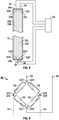
- a fault detection unit 52 is electrically connected to a plurality of cords 32 of the belt 16.
- the fault detection unit 52 is connected to a terminated portion of the belt 16, for example, at an end 24a and/or 24b of the belt 16 located at the support 26 (shown in FIG. 1 ).
- the cords 32 are electrically connected to the fault detection unit 52 in a Wheatstone bridge configuration.
- each cord 32a, 32b, 32c and 32d of a four-cord 32 arrangement forms each leg of the Wheatstone bridge.
- Cord ends 32A and 32B are connected via input leads 54, while cord ends 32C and 32D are connected via input leads 54.
- Each leg 60 of the bridge circuit 58 is an LCR circuit allowing for measurement of complex impedance of the legs 60 or alternatively resistance of the legs 60.
- An excitation voltage is applied across the bridge circuit 58 via the input leads 54 from the fault detection unit 52 in the form of an AC voltage , or alternatively a DC voltage source, and the bridge circuit 58 outputs a signal voltage via output leads 56 to the fault detection unit 52.
- the fault detection unit 52 compares the excitation voltage to the signal voltage and evaluates an electrical impedance and/or electrical resistance of the belt 16.
- the measurements are dynamic such that changes in complex impedance or electrical resistance are evaluated by the detection unit 52 and are indicative of wear, fretting and wire breakage in the cords 32 of the belt 16.
- Configuring the cords 32 as a bridge circuit 58 suppresses noise from electromagnetic interference (EMI), temperature variation along a length of the cords 32, and tensile load variation along each cord 32.
- EMI electromagnetic interference
- the connection scheme increases the total resistance of the circuit 58 and reduced the interrogating current through the cords 32, thus improving signal to noise ratio. Further, since the cords 32 are all interconnected in the circuit 58, all of the cords 32 are monitored simultaneously, thus reducing a number of required measurement channels.
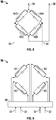
- the belt 16 includes 8 cords 32, with adjacent cords 32 arranged in cord-pairs 64A, 64B, 64C and 64D.
- the configuration of FIG. 7 is utilized when, for example, the first end 24a of the belt 16 is fixed and the second end 24b is not fixed, as in the elevator system 10 of FIG. 2 .
- the individual cords 32 of each cord-pair 64A, 64B, 64C, 64D are connected at the second end 24b by jumper wires 66.
- the cord pairs 64A, 64B, 64C, 64D are interconnected to form the bridge circuit 58.
- cord-pair 64A is connected to cord-pair 64B
- cord-pair 64B is connected to cord-pair 64C
- cord-pair 64C is connected to cord-pair 64D
- cord-pair 64D is connected to cord-pair 64A.
- voltage is applied across the bridge circuit 58 via the input leads 54 and output leads 56 from the fault detection unit 52 measures an electrical impedance and/or electrical resistance of the belt 16.
- an output voltage at the output leads 56 indicates a difference in impedance of cord-pairs 64A and 64D from cord-pairs 64B and 64C, or inner cords 32 of the belt 16 compared to outer cords 32 of the belt 16.
- cords 32 of cord-pairs 64A, 64B, 64C and 64D are illustrated as connected external to the jacket 34, in some embodiments, the cords 32 are connected internal to the jacket 34. Further, while embodiments of belts 16 having 4 or 8 cords 32 are illustrated, it is to be appreciated that in other embodiments, belts 16 having any number of cords 32 four or greater may be utilized, with select cords 32 connected as bridge circuit 58 at any one time.
- the cords 32 are connected to a switch array 68 including one or more relays or other switching elements.
- the cords 32 are selectably connected fault detection unit 52.
- the fault detection unit 52 may assess the condition of the single cord 32 via, for example, a traditional resistance-based inspection process.
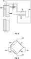
- a combination of cords 32 and fixed resistors 70 may be used to define the bridge circuit 58.
- two cords 32c and 32d are used in combination with two resistors 70, for example, two low inductance resistors 70, to form the bridge circuit 58.
- Output leads 56 are connected between cords 32 and resistors 70 and the fault detection unit 52 essentially compares the complex impedance of the cords 32c and 32d to the impedance of the fixed resistors 70.
- the impedance of the fixed resistors 70 is stable, while the impedance of cords 32c and 32d is variable, so change in impedance of the cords 32c, 32d is more easily detectable.
- the resistor 70 legs are low inductance and may also be temperature matched utilizing thermocouples and heaters (not shown). Further, the resistors 70 are matched to the cord impedance within 0.5 to 10x of the cord impedance.
- cord pairs 64A and 64B are connected to form two legs of the bridge circuit 58, while resistors 70 for the other two legs.
- the behavior of this bridge circuit 58 is similar to that of the circuit in FIGs. 10-11 , but with higher levels of cord impedance. Additional cords 32 may be connected in series to form legs 64A and 64B.
- the cords 32 and resistors 70 are interconnected such that the bridge circuit 58 is formed with cords 32 at opposing legs, and likewise resistors 70 at opposing legs, as opposed to at adjacent legs.
- the bridge circuit 58 is formed with cords 32 at opposing legs, and likewise resistors 70 at opposing legs, as opposed to at adjacent legs.
- an increase in complex impedance in the cords 32 will unbalance the bridge in opposite directions, resulting in approximately double the measurable signal at the fault detection unit 52.
- a smaller change in impedance in the cords 32 is detectable.
Landscapes
- Physics & Mathematics (AREA)
- General Physics & Mathematics (AREA)
- Engineering & Computer Science (AREA)
- Automation & Control Theory (AREA)
- Structural Engineering (AREA)
- Lift-Guide Devices, And Elevator Ropes And Cables (AREA)
Claims (12)
- Verfahren zur Fehlererkennung auf einem Band oder Seil, umfassend:Verbinden zweier Stränge (32c, 32d) des Bandes oder Seils (16), wobei die Stränge (32c, 32d) eine Vielzahl an Drähten beinhalten, um eine Brückenschaltung (58) zu bilden, wobei die Stränge (32c, 32d) elektrisch mit einer Fehlererkennungseinheit (52) in einer Wheatstone-Brücken-Konfiguration mit zwei Festwiderständen (70) verbunden sind;Aussetzen der Brückenschaltung (58) gegenüber einer Erregungsspannung;Ausgeben einer Signalspannung von der Brückenschaltung (58), wobei die Struktur der Brückenschaltung Umgebungsrauschen unterdrückt, um das Signal-Rausch-Verhältnis der Signalspannung zu steigern; undÜberwachen der Signalspannung, um einen Fehlerzustand des Seils zu erkennen; wobei zwei Schenkel der Brückenschaltung jeweils einen Festwiderstand (70) umfassen, unddadurch gekennzeichnet, dass zwei Schenkel der Brückenschaltung jeweils nur einen Strang umfassen, wobei die Fehlererkennungseinheit (52) die komplexe Impedanz der Stränge (32c, 32d) mit der Impedanz der Festwiderstände (70) vergleicht.
- Verfahren nach Anspruch 1, ferner umfassend:(a) Vergleichen der Signalspannung mit der Erregungsspannung in Größe und Phase, um den Fehlerzustand des Seils zu erkennen; oder(b) Vergleichen eines Profils einer gemessenen elektrischen Impedanz mit einem grundlegenden elektrischen Impedanzprofil; undBestimmen eines Fehlerzustands des Bandes oder Seils anhand des Vergleichs.
- Verfahren nach einem der vorhergehenden Ansprüche, wobei die Ausgangsspannung proportional zu einem Unterschied in der Impedanz zwischen den Strängen (32c, 32d) ist.
- Verfahren nach Anspruch 3, wobei die Ausgangsspannung indikativ für einen Unterschied in der Impedanz zwischen lateral inneren Strängen des Bandes und lateral äußeren Strängen des Bandes ist.
- Verfahren nach einem der vorhergehenden Ansprüche, wobei Fehlerzustände Drahtbrüche, Reibverschleiß und/oder Korbbildung beinhalten.
- Verfahren nach einem der vorhergehenden Ansprüche, wobei die elektrische Impedanz substanziell kontinuierlich gemessen wird.
- Verfahren nach einem der vorhergehenden Ansprüche, ferner umfassend Schalten der Verbindung der Stränge (32c, 32d) über einen Schaltmechanismus (68), der mit den Strängen (32c, 32d) wirkverbunden ist.
- Verfahren nach einem der vorhergehenden Ansprüche, wobei die Erregungsspannung von einer Wechselspannungsquelle bereitgestellt wird.
- Aufzugsystem, umfassend:eine Aufzugkabine (12);eine oder mehrere Seilrollen (18);ein Band oder Seil (16), das eine Vielzahl an Drähten (28) umfasst, die in einer Vielzahl an Strängen (32) angeordnet sind, für das Unterstützen und/oder Antreiben der Aufzugkabine (12), die über die eine oder die mehreren Laufrollen (18) laufen und mit der Aufzugkabine (12) wirkverbunden sind, wobei zwei Stränge der Vielzahl an Strängen (32) miteinander verbunden sind, um eine Brückenschaltung (58) zu bilden, wobei die Stränge (32c, 32d) elektrisch mit einer Fehlererkennungseinheit (52) in einer Wheatstone-Brücken-Konfiguration verbunden sind, wobei zwei Schenkel der Brückenschaltung jeweils einen Festwiderstand (70) umfassen und dadurch gekennzeichnet, dass zwei Schenkel der Brückenschaltung jeweils nur einen Strang umfassen, wobei die Fehlererkennungseinheit (52) so angeordnet ist, dass sie die komplexe Impedanz der Stränge (32c, 32d) mit der Impedanz der Festwiderstände (70) vergleicht.
- Aufzugsystem nach Anspruch 9, ferner umfassend ein Schaltelement (68), das mit der Vielzahl an Strängen (32) wirkverbunden ist, um eine Verbindungskonfiguration der Vielzahl an Strängen (32) zu ändern.
- Aufzugsystem nach einem der Ansprüche 9-10, ferner umfassend eine Wechselspannungsquelle, die mit dem Band oder Seil (16) wirkverbunden ist.
- Aufzugsystem nach einem der Ansprüche 9-11, wobei das Band oder Seil (16) ein beschichtetes Band oder Seil ist.
Applications Claiming Priority (1)
| Application Number | Priority Date | Filing Date | Title |
|---|---|---|---|
| PCT/US2013/027013 WO2014130028A1 (en) | 2013-02-21 | 2013-02-21 | Elevator cord health monitoring |
Publications (3)
| Publication Number | Publication Date |
|---|---|
| EP2958845A1 EP2958845A1 (de) | 2015-12-30 |
| EP2958845A4 EP2958845A4 (de) | 2016-10-26 |
| EP2958845B1 true EP2958845B1 (de) | 2020-05-13 |
Family
ID=51391662
Family Applications (1)
| Application Number | Title | Priority Date | Filing Date |
|---|---|---|---|
| EP13875665.5A Active EP2958845B1 (de) | 2013-02-21 | 2013-02-21 | Integritätsüberwachung für aufzugsseil |
Country Status (4)
| Country | Link |
|---|---|
| US (1) | US9862571B2 (de) |
| EP (1) | EP2958845B1 (de) |
| CN (1) | CN105073618A (de) |
| WO (1) | WO2014130028A1 (de) |
Families Citing this family (24)
| Publication number | Priority date | Publication date | Assignee | Title |
|---|---|---|---|---|
| CN105246814A (zh) * | 2013-05-28 | 2016-01-13 | 因温特奥股份公司 | 电梯设备 |
| HK1223344A1 (zh) * | 2013-10-22 | 2017-07-28 | 通力股份公司 | 用於检查电梯系统的负载承载元件的完整性的方法和设备 |
| FI126182B (en) * | 2014-06-17 | 2016-07-29 | Kone Corp | Method and arrangement for monitoring the condition of an elevator rope |
| EP3028979A1 (de) * | 2014-12-01 | 2016-06-08 | KONE Corporation | Verfahren zur Herstellung einer elektrischen Kontaktanordnung und Kontaktanordnung |
| US9932203B2 (en) * | 2015-07-31 | 2018-04-03 | Inventio Ag | Method and device for detecting a deterioration state of a load bearing capacity in a suspension member arrangement for an elevator |
| WO2017032914A1 (en) * | 2015-08-21 | 2017-03-02 | Kone Corporation | Arrangement and methods for condition monitoring of the traction belt and/or the traction belt termination |
| EP3336036B1 (de) * | 2016-12-16 | 2021-02-03 | KONE Corporation | Verfahren und anordnung zur zustandsüberwachung eines förderseils einer hebevorrichtung |
| WO2018116327A1 (en) * | 2016-12-23 | 2018-06-28 | Redaelli Tecna S.P.A. | Monitoring sensor for a rope of cableway systems |
| US11945691B2 (en) * | 2017-01-31 | 2024-04-02 | Inventio Ag | Elevator with a monitoring arrangement for monitoring an integrity of suspension members |
| WO2018141553A1 (en) * | 2017-01-31 | 2018-08-09 | Inventio Ag | Suspension member arrangement for an elevator and monitoring arrangement for monitoring a suspension member |
| AU2018288311B2 (en) * | 2017-06-21 | 2021-06-17 | Inventio Ag | Elevator with a monitoring arrangement for monitoring an integrity of suspension members with separated circuitries |
| WO2018234007A1 (en) | 2017-06-21 | 2018-12-27 | Inventio Ag | Method for self-testing a monitoring device monitoring an integrity status of a suspension member arrangement in an elevator |
| US20210323790A1 (en) * | 2018-01-29 | 2021-10-21 | Inventio Ag | Concepts for detecting a deterioration state of a load bearing capacity in a suspension member arrangement for an elevator |
| WO2020198745A1 (en) * | 2019-03-28 | 2020-10-01 | Liftwave, Inc. Dba Rise Robotics | Flat belt condition monitoring and heating system |
| GR1009762B (el) * | 2019-06-12 | 2020-06-09 | Ευαγγελος Νικολαου Κλαμπανης | Μηχανισμος εντοπισμου τασης εκτροπης, εκτροπης και φθορας συρματοσχοινου |
| EP3820031B1 (de) | 2019-11-05 | 2025-02-26 | Hamilton Sundstrand Corporation | Leistungsvorrichtungsgesundheitsüberwachung unter verwendung einer brückenanordnung |
| CN110980471B (zh) * | 2019-12-31 | 2020-12-01 | 界首市迅立达电梯有限公司 | 一种基于物联网的电梯曳引机钢丝绳状态预警系统 |
| US20210339984A1 (en) * | 2020-04-29 | 2021-11-04 | Tk Elevator Innovation And Operations Gmbh | Methods of monitoring the condition of elevator belts |
| US11447369B2 (en) * | 2020-05-12 | 2022-09-20 | Otis Elevator Company | Electrically heated elevator tension member |
| CN113086792B (zh) * | 2021-03-26 | 2022-05-03 | 广州广日电梯工业有限公司 | 电梯曳引部件的维护方法以及电梯曳引部件的维护装置 |
| CN113406151A (zh) * | 2021-06-18 | 2021-09-17 | 秦皇岛开发区前景光电技术有限公司 | 钢带断丝检测方法及系统 |
| US12570501B2 (en) | 2022-02-25 | 2026-03-10 | Tk Elevator Innovation And Operations Gmbh | Condition monitoring system for elevator hoisting members |
| CN115077769A (zh) * | 2022-08-22 | 2022-09-20 | 苏州铁近机电科技股份有限公司 | 皮带检测装置 |
| CN120027862B (zh) * | 2025-04-18 | 2025-06-24 | 国网浙江省电力有限公司杭州供电公司 | 一种对配电站房的自动化监测方法、系统、设备及介质 |
Family Cites Families (15)
| Publication number | Priority date | Publication date | Assignee | Title |
|---|---|---|---|---|
| US2657352A (en) * | 1949-07-11 | 1953-10-27 | Cons Eng Corp | Bridge circuit |
| US3958455A (en) * | 1973-09-21 | 1976-05-25 | Russell John D | Force transducer for strain gage |
| FI107249B (fi) | 1996-12-20 | 2001-06-29 | Kone Corp | Menetelmä ja laitteisto hissin kuorman mittaamiseksi |
| US6633159B1 (en) * | 1999-03-29 | 2003-10-14 | Otis Elevator Company | Method and apparatus for magnetic detection of degradation of jacketed elevator rope |
| WO2001035526A2 (en) * | 1999-11-09 | 2001-05-17 | That Corporation | Improved floating, balanced output circuit |
| US20010045835A1 (en) | 2000-02-25 | 2001-11-29 | Ahmed Adel Abdel Aziz | Method and apparatus for detecting timing belt damage by inductive coupling |
| GB2371667B (en) * | 2000-10-27 | 2004-07-28 | Ford Global Tech Inc | Vehicle occupant mass sensing system |
| US20020194935A1 (en) * | 2001-06-26 | 2002-12-26 | Arthur Clarke | Tensile load sensing belt |
| JP2005139001A (ja) | 2003-11-04 | 2005-06-02 | Inventio Ag | 支持手段を点検する方法および装置 |
| US7441464B2 (en) * | 2006-11-08 | 2008-10-28 | Honeywell International Inc. | Strain gauge sensor system and method |
| US8312987B2 (en) | 2008-01-16 | 2012-11-20 | The Gates Corporation | Belt monitoring systems and methods |
| BRPI0923524B1 (pt) | 2008-12-22 | 2021-02-23 | Inventio Ag | processo para monitoramento de um meio de suporte de elevador, dispositivo de monitoramento de meio de suporte de elevador e unidade de elevador com um dispositivo de monitoramento |
| WO2011085885A2 (de) * | 2009-12-21 | 2011-07-21 | Inventio Ag | Überwachung eines trag- und treibmittels einer aufzugsanlage |
| WO2012030332A1 (en) * | 2010-09-01 | 2012-03-08 | Otis Elevator Company | Resistance-based monitoring system and method |
| AU2013361005B2 (en) | 2012-12-18 | 2017-01-05 | Inventio Ag | Lift system with monitoring device and method for monitoring a lift system |
-
2013
- 2013-02-21 EP EP13875665.5A patent/EP2958845B1/de active Active
- 2013-02-21 WO PCT/US2013/027013 patent/WO2014130028A1/en not_active Ceased
- 2013-02-21 CN CN201380073605.7A patent/CN105073618A/zh active Pending
- 2013-02-21 US US14/768,667 patent/US9862571B2/en active Active
Non-Patent Citations (1)
| Title |
|---|
| None * |
Also Published As
| Publication number | Publication date |
|---|---|
| CN105073618A (zh) | 2015-11-18 |
| EP2958845A4 (de) | 2016-10-26 |
| EP2958845A1 (de) | 2015-12-30 |
| WO2014130028A1 (en) | 2014-08-28 |
| US20160002006A1 (en) | 2016-01-07 |
| US9862571B2 (en) | 2018-01-09 |
Similar Documents
| Publication | Publication Date | Title |
|---|---|---|
| EP2958845B1 (de) | Integritätsüberwachung für aufzugsseil | |
| US9731939B2 (en) | Elevator cord health monitoring | |
| US9796561B2 (en) | Wear detection for coated belt or rope | |
| EP2834627B1 (de) | Kalibrierung eines verschleisserkennungssystems | |
| AU2009331700B2 (en) | Method for monitoring an elevator support means, an elevator support means monitoring device, and an elevator system having such a monitoring device | |
| AU2002358252B2 (en) | Lift belt system | |
| CN110002321B (zh) | 用于提升设备的绳索的状态监测的方法和装置 | |
| EP1461490B1 (de) | Kunstofffaserseil mit ferromagnitischem element das eine lokale beanspruchung angibt | |
| EP3107855B1 (de) | Verbinder für system zur inspektion eines aufzugsspanngliedes | |
| HK1077605B (en) | Method of determining the condition of rope having a ferromagnetic element providing an indication of local strain |
Legal Events
| Date | Code | Title | Description |
|---|---|---|---|
| PUAI | Public reference made under article 153(3) epc to a published international application that has entered the european phase |
Free format text: ORIGINAL CODE: 0009012 |
|
| 17P | Request for examination filed |
Effective date: 20150921 |
|
| AK | Designated contracting states |
Kind code of ref document: A1 Designated state(s): AL AT BE BG CH CY CZ DE DK EE ES FI FR GB GR HR HU IE IS IT LI LT LU LV MC MK MT NL NO PL PT RO RS SE SI SK SM TR |
|
| AX | Request for extension of the european patent |
Extension state: BA ME |
|
| DAX | Request for extension of the european patent (deleted) | ||
| A4 | Supplementary search report drawn up and despatched |
Effective date: 20160928 |
|
| RIC1 | Information provided on ipc code assigned before grant |
Ipc: B66B 7/12 20060101ALI20160922BHEP Ipc: B66B 5/24 20060101AFI20160922BHEP Ipc: B66B 5/02 20060101ALI20160922BHEP |
|
| RAP1 | Party data changed (applicant data changed or rights of an application transferred) |
Owner name: OTIS ELEVATOR COMPANY |
|
| STAA | Information on the status of an ep patent application or granted ep patent |
Free format text: STATUS: EXAMINATION IS IN PROGRESS |
|
| 17Q | First examination report despatched |
Effective date: 20171027 |
|
| GRAP | Despatch of communication of intention to grant a patent |
Free format text: ORIGINAL CODE: EPIDOSNIGR1 |
|
| STAA | Information on the status of an ep patent application or granted ep patent |
Free format text: STATUS: GRANT OF PATENT IS INTENDED |
|
| INTG | Intention to grant announced |
Effective date: 20200220 |
|
| GRAS | Grant fee paid |
Free format text: ORIGINAL CODE: EPIDOSNIGR3 |
|
| GRAA | (expected) grant |
Free format text: ORIGINAL CODE: 0009210 |
|
| STAA | Information on the status of an ep patent application or granted ep patent |
Free format text: STATUS: THE PATENT HAS BEEN GRANTED |
|
| AK | Designated contracting states |
Kind code of ref document: B1 Designated state(s): AL AT BE BG CH CY CZ DE DK EE ES FI FR GB GR HR HU IE IS IT LI LT LU LV MC MK MT NL NO PL PT RO RS SE SI SK SM TR |
|
| REG | Reference to a national code |
Ref country code: GB Ref legal event code: FG4D |
|
| REG | Reference to a national code |
Ref country code: CH Ref legal event code: EP |
|
| REG | Reference to a national code |
Ref country code: DE Ref legal event code: R096 Ref document number: 602013069147 Country of ref document: DE |
|
| REG | Reference to a national code |
Ref country code: AT Ref legal event code: REF Ref document number: 1270011 Country of ref document: AT Kind code of ref document: T Effective date: 20200615 |
|
| REG | Reference to a national code |
Ref country code: LT Ref legal event code: MG4D |
|
| REG | Reference to a national code |
Ref country code: NL Ref legal event code: MP Effective date: 20200513 |
|
| PG25 | Lapsed in a contracting state [announced via postgrant information from national office to epo] |
Ref country code: FI Free format text: LAPSE BECAUSE OF FAILURE TO SUBMIT A TRANSLATION OF THE DESCRIPTION OR TO PAY THE FEE WITHIN THE PRESCRIBED TIME-LIMIT Effective date: 20200513 Ref country code: PT Free format text: LAPSE BECAUSE OF FAILURE TO SUBMIT A TRANSLATION OF THE DESCRIPTION OR TO PAY THE FEE WITHIN THE PRESCRIBED TIME-LIMIT Effective date: 20200914 Ref country code: SE Free format text: LAPSE BECAUSE OF FAILURE TO SUBMIT A TRANSLATION OF THE DESCRIPTION OR TO PAY THE FEE WITHIN THE PRESCRIBED TIME-LIMIT Effective date: 20200513 Ref country code: LT Free format text: LAPSE BECAUSE OF FAILURE TO SUBMIT A TRANSLATION OF THE DESCRIPTION OR TO PAY THE FEE WITHIN THE PRESCRIBED TIME-LIMIT Effective date: 20200513 Ref country code: GR Free format text: LAPSE BECAUSE OF FAILURE TO SUBMIT A TRANSLATION OF THE DESCRIPTION OR TO PAY THE FEE WITHIN THE PRESCRIBED TIME-LIMIT Effective date: 20200814 Ref country code: NO Free format text: LAPSE BECAUSE OF FAILURE TO SUBMIT A TRANSLATION OF THE DESCRIPTION OR TO PAY THE FEE WITHIN THE PRESCRIBED TIME-LIMIT Effective date: 20200813 Ref country code: IS Free format text: LAPSE BECAUSE OF FAILURE TO SUBMIT A TRANSLATION OF THE DESCRIPTION OR TO PAY THE FEE WITHIN THE PRESCRIBED TIME-LIMIT Effective date: 20200913 |
|
| PG25 | Lapsed in a contracting state [announced via postgrant information from national office to epo] |
Ref country code: RS Free format text: LAPSE BECAUSE OF FAILURE TO SUBMIT A TRANSLATION OF THE DESCRIPTION OR TO PAY THE FEE WITHIN THE PRESCRIBED TIME-LIMIT Effective date: 20200513 Ref country code: BG Free format text: LAPSE BECAUSE OF FAILURE TO SUBMIT A TRANSLATION OF THE DESCRIPTION OR TO PAY THE FEE WITHIN THE PRESCRIBED TIME-LIMIT Effective date: 20200813 Ref country code: LV Free format text: LAPSE BECAUSE OF FAILURE TO SUBMIT A TRANSLATION OF THE DESCRIPTION OR TO PAY THE FEE WITHIN THE PRESCRIBED TIME-LIMIT Effective date: 20200513 Ref country code: HR Free format text: LAPSE BECAUSE OF FAILURE TO SUBMIT A TRANSLATION OF THE DESCRIPTION OR TO PAY THE FEE WITHIN THE PRESCRIBED TIME-LIMIT Effective date: 20200513 |
|
| REG | Reference to a national code |
Ref country code: AT Ref legal event code: MK05 Ref document number: 1270011 Country of ref document: AT Kind code of ref document: T Effective date: 20200513 |
|
| PG25 | Lapsed in a contracting state [announced via postgrant information from national office to epo] |
Ref country code: NL Free format text: LAPSE BECAUSE OF FAILURE TO SUBMIT A TRANSLATION OF THE DESCRIPTION OR TO PAY THE FEE WITHIN THE PRESCRIBED TIME-LIMIT Effective date: 20200513 Ref country code: AL Free format text: LAPSE BECAUSE OF FAILURE TO SUBMIT A TRANSLATION OF THE DESCRIPTION OR TO PAY THE FEE WITHIN THE PRESCRIBED TIME-LIMIT Effective date: 20200513 |
|
| PG25 | Lapsed in a contracting state [announced via postgrant information from national office to epo] |
Ref country code: DK Free format text: LAPSE BECAUSE OF FAILURE TO SUBMIT A TRANSLATION OF THE DESCRIPTION OR TO PAY THE FEE WITHIN THE PRESCRIBED TIME-LIMIT Effective date: 20200513 Ref country code: IT Free format text: LAPSE BECAUSE OF FAILURE TO SUBMIT A TRANSLATION OF THE DESCRIPTION OR TO PAY THE FEE WITHIN THE PRESCRIBED TIME-LIMIT Effective date: 20200513 Ref country code: AT Free format text: LAPSE BECAUSE OF FAILURE TO SUBMIT A TRANSLATION OF THE DESCRIPTION OR TO PAY THE FEE WITHIN THE PRESCRIBED TIME-LIMIT Effective date: 20200513 Ref country code: EE Free format text: LAPSE BECAUSE OF FAILURE TO SUBMIT A TRANSLATION OF THE DESCRIPTION OR TO PAY THE FEE WITHIN THE PRESCRIBED TIME-LIMIT Effective date: 20200513 Ref country code: SM Free format text: LAPSE BECAUSE OF FAILURE TO SUBMIT A TRANSLATION OF THE DESCRIPTION OR TO PAY THE FEE WITHIN THE PRESCRIBED TIME-LIMIT Effective date: 20200513 Ref country code: RO Free format text: LAPSE BECAUSE OF FAILURE TO SUBMIT A TRANSLATION OF THE DESCRIPTION OR TO PAY THE FEE WITHIN THE PRESCRIBED TIME-LIMIT Effective date: 20200513 Ref country code: CZ Free format text: LAPSE BECAUSE OF FAILURE TO SUBMIT A TRANSLATION OF THE DESCRIPTION OR TO PAY THE FEE WITHIN THE PRESCRIBED TIME-LIMIT Effective date: 20200513 Ref country code: ES Free format text: LAPSE BECAUSE OF FAILURE TO SUBMIT A TRANSLATION OF THE DESCRIPTION OR TO PAY THE FEE WITHIN THE PRESCRIBED TIME-LIMIT Effective date: 20200513 |
|
| REG | Reference to a national code |
Ref country code: DE Ref legal event code: R097 Ref document number: 602013069147 Country of ref document: DE |
|
| PG25 | Lapsed in a contracting state [announced via postgrant information from national office to epo] |
Ref country code: PL Free format text: LAPSE BECAUSE OF FAILURE TO SUBMIT A TRANSLATION OF THE DESCRIPTION OR TO PAY THE FEE WITHIN THE PRESCRIBED TIME-LIMIT Effective date: 20200513 Ref country code: SK Free format text: LAPSE BECAUSE OF FAILURE TO SUBMIT A TRANSLATION OF THE DESCRIPTION OR TO PAY THE FEE WITHIN THE PRESCRIBED TIME-LIMIT Effective date: 20200513 |
|
| PLBE | No opposition filed within time limit |
Free format text: ORIGINAL CODE: 0009261 |
|
| STAA | Information on the status of an ep patent application or granted ep patent |
Free format text: STATUS: NO OPPOSITION FILED WITHIN TIME LIMIT |
|
| 26N | No opposition filed |
Effective date: 20210216 |
|
| PG25 | Lapsed in a contracting state [announced via postgrant information from national office to epo] |
Ref country code: SI Free format text: LAPSE BECAUSE OF FAILURE TO SUBMIT A TRANSLATION OF THE DESCRIPTION OR TO PAY THE FEE WITHIN THE PRESCRIBED TIME-LIMIT Effective date: 20200513 |
|
| PG25 | Lapsed in a contracting state [announced via postgrant information from national office to epo] |
Ref country code: MC Free format text: LAPSE BECAUSE OF FAILURE TO SUBMIT A TRANSLATION OF THE DESCRIPTION OR TO PAY THE FEE WITHIN THE PRESCRIBED TIME-LIMIT Effective date: 20200513 |
|
| GBPC | Gb: european patent ceased through non-payment of renewal fee |
Effective date: 20210221 |
|
| REG | Reference to a national code |
Ref country code: BE Ref legal event code: MM Effective date: 20210228 |
|
| PG25 | Lapsed in a contracting state [announced via postgrant information from national office to epo] |
Ref country code: LI Free format text: LAPSE BECAUSE OF NON-PAYMENT OF DUE FEES Effective date: 20210228 Ref country code: LU Free format text: LAPSE BECAUSE OF NON-PAYMENT OF DUE FEES Effective date: 20210221 Ref country code: CH Free format text: LAPSE BECAUSE OF NON-PAYMENT OF DUE FEES Effective date: 20210228 |
|
| PG25 | Lapsed in a contracting state [announced via postgrant information from national office to epo] |
Ref country code: GB Free format text: LAPSE BECAUSE OF NON-PAYMENT OF DUE FEES Effective date: 20210221 Ref country code: IE Free format text: LAPSE BECAUSE OF NON-PAYMENT OF DUE FEES Effective date: 20210221 |
|
| PG25 | Lapsed in a contracting state [announced via postgrant information from national office to epo] |
Ref country code: BE Free format text: LAPSE BECAUSE OF NON-PAYMENT OF DUE FEES Effective date: 20210228 |
|
| PG25 | Lapsed in a contracting state [announced via postgrant information from national office to epo] |
Ref country code: HU Free format text: LAPSE BECAUSE OF FAILURE TO SUBMIT A TRANSLATION OF THE DESCRIPTION OR TO PAY THE FEE WITHIN THE PRESCRIBED TIME-LIMIT; INVALID AB INITIO Effective date: 20130221 |
|
| PG25 | Lapsed in a contracting state [announced via postgrant information from national office to epo] |
Ref country code: CY Free format text: LAPSE BECAUSE OF FAILURE TO SUBMIT A TRANSLATION OF THE DESCRIPTION OR TO PAY THE FEE WITHIN THE PRESCRIBED TIME-LIMIT Effective date: 20200513 |
|
| PG25 | Lapsed in a contracting state [announced via postgrant information from national office to epo] |
Ref country code: MK Free format text: LAPSE BECAUSE OF FAILURE TO SUBMIT A TRANSLATION OF THE DESCRIPTION OR TO PAY THE FEE WITHIN THE PRESCRIBED TIME-LIMIT Effective date: 20200513 |
|
| PG25 | Lapsed in a contracting state [announced via postgrant information from national office to epo] |
Ref country code: MT Free format text: LAPSE BECAUSE OF FAILURE TO SUBMIT A TRANSLATION OF THE DESCRIPTION OR TO PAY THE FEE WITHIN THE PRESCRIBED TIME-LIMIT Effective date: 20200513 |
|
| PG25 | Lapsed in a contracting state [announced via postgrant information from national office to epo] |
Ref country code: TR Free format text: LAPSE BECAUSE OF FAILURE TO SUBMIT A TRANSLATION OF THE DESCRIPTION OR TO PAY THE FEE WITHIN THE PRESCRIBED TIME-LIMIT Effective date: 20200513 |
|
| PGFP | Annual fee paid to national office [announced via postgrant information from national office to epo] |
Ref country code: DE Payment date: 20260121 Year of fee payment: 14 |
|
| PGFP | Annual fee paid to national office [announced via postgrant information from national office to epo] |
Ref country code: FR Payment date: 20260121 Year of fee payment: 14 |