EP2959043B1 - Machine a tisser pour tissu triaxial avec dispositif statique pour la formation de la foule - Google Patents
Machine a tisser pour tissu triaxial avec dispositif statique pour la formation de la foule Download PDFInfo
- Publication number
- EP2959043B1 EP2959043B1 EP14714369.7A EP14714369A EP2959043B1 EP 2959043 B1 EP2959043 B1 EP 2959043B1 EP 14714369 A EP14714369 A EP 14714369A EP 2959043 B1 EP2959043 B1 EP 2959043B1
- Authority
- EP
- European Patent Office
- Prior art keywords
- yarn
- oblique
- warp yarns
- assembly
- weft
- Prior art date
- Legal status (The legal status is an assumption and is not a legal conclusion. Google has not performed a legal analysis and makes no representation as to the accuracy of the status listed.)
- Active
Links
Images


Classifications
-
- D—TEXTILES; PAPER
- D03—WEAVING
- D03C—SHEDDING MECHANISMS; PATTERN CARDS OR CHAINS; PUNCHING OF CARDS; DESIGNING PATTERNS
- D03C13/00—Shedding mechanisms not otherwise provided for
-
- D—TEXTILES; PAPER
- D03—WEAVING
- D03D—WOVEN FABRICS; METHODS OF WEAVING; LOOMS
- D03D13/00—Woven fabrics characterised by the special disposition of the warp or weft threads, e.g. with curved weft threads, with discontinuous warp threads, with diagonal warp or weft
- D03D13/002—With diagonal warps or wefts
-
- D—TEXTILES; PAPER
- D03—WEAVING
- D03D—WOVEN FABRICS; METHODS OF WEAVING; LOOMS
- D03D41/00—Looms not otherwise provided for, e.g. for weaving chenille yarn; Details peculiar to these looms
-
- D—TEXTILES; PAPER
- D03—WEAVING
- D03D—WOVEN FABRICS; METHODS OF WEAVING; LOOMS
- D03D47/00—Looms in which bulk supply of weft does not pass through shed, e.g. shuttleless looms, gripper shuttle looms, dummy shuttle looms
- D03D47/27—Drive or guide mechanisms for weft inserting
- D03D47/271—Rapiers
- D03D47/273—Rapier rods
Definitions
- the present invention belongs to the sector of the automatic looms used to produce triaxial fabrics. Specifically, triaxial fabrics of the so-called bidimensional type.
- An automatic loom is a machine used to produce fabrics through an appropriate interlacing of yarns, called weft and warp respectively, usually perpendicular to each other.
- a machine usually operates in conjunction with other machines which perform auxiliary functions, for instance feeding the yarns necessary to form the fabric, or thin strips called tapes, used instead of the yarns.
- the interlacing of the weft and warp yarns results in a bidimensional fabric, featuring two axes substantially perpendicular to each other. Such an arrangement limits both the visual and tactile effects obtainable and the mechanical properties of the fabric, as touched on in US 6494235 that describes a weaving machine.
- FIG. 1 An example of triaxial fabric (1) of the bidimensional type is shown in Fig. 1 . This figure shows the directions of the warp yarns and of the weft yarns.
- Machines for the production of triaxial fabrics that sew or glue fibers or superimposed yarns are known.
- a bidimensional fabric featuring a weft orthogonal to the warp can be transformed into a bidimensional fabric featuring an oblique weft and subsequently sewn with a third yarn, so as to produce a triaxial fabric.
- Similar systems are described in many patent applications, including, amongst others, patent application EP 0250044 (A1).
- the principle of superimposing two layers of yarns, one of which oblique is known for long time and is already described, for instance, in US 2985941 (A ).
- Patent application US 3799209 (A ) describes a machine that is particularly suitable for the production of a triaxial fabric of the type described in patent application US 3446251 (A ) mentioned above.
- the warp yarns are guided by a series of heddles which handle them in such a way as to allow their mutual crossing.
- Gaps also referred to as sheds, are formed during said handling and are used to insert the weft yarn.
- Said machine developed starting from already known principles and mechanisms, is extremely complex and bulky.
- the movements of the elements of the machine shall be very accurate and the just described mechanism shall be repeated a high number of times in order to get a strip of fabric that extends for a reasonable width, consequently the repetition of many auxiliary handling elements shall be provided.
- patent application US 3999578 (A ) describes some improvements related to the insertion of the weft yarn which, on the other hand, don't solve the mentioned problems.
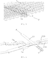
- the present invention aims at solving the problems highlighted above by reducing both the complexity of the systems used and the overall dimensions of the loom with respect to the width of the fabric produced. Said characteristics are obtained thanks to the combined use of an innovative oblique weaving front and a combined warp yarn guide and oblique fixed weft feeding system.
- the weaving front F corresponds to the direction of the inserted oblique weft yarn.
- said weaving front F is oblique, i.e. the direction is incident, but not perpendicular to the X direction of the warp yarns (21). This detail is clearly shown in Fig. 2 .
- the loom for triaxial fabric (1) according to the present invention is capable of producing fabrics starting from different kinds of textile materials, including, but not limited to, yarns, tapes, multi-filament yarns.
- the assembly (2) used to feed the series of warp yarns can assume different arrangements, for instance it can be formed of one or two beams (22) or one or several creels.
- the warp yarns are handled, via the traction exerted by the bolt, by a move-forward assembly (3).
- the warp is preferably driven by means of the traction exerted by the already formed bolt of fabric (1) that is rolled up around the motor-driven reel (31).
- said move-forward assembly (3) can include one or several motor-driven cylinders whose side surfaces exert an auxiliary friction driving action onto the already formed bolt of fabric (1).
- said one or several motor-driven cylinders can exert a traction sufficient for bolt traction and/or warp yarn driving.
- said one or several motor-driven cylinders can be installed even before the weaving front F, so as to make slip-off from the creel or unrolling from the beam(s) easier.
- the former performs a warp yarn (21) unrolling or slip-off function
- the second perform a triaxial fabric (1) bolt traction function, and both also act onto the tension the yarns are subjected to.
- the amount of the latter tensions conforms to different requirements that take place in the individual areas of the loom. For instance, said tensions can make the passage of the cursor on the weaving front easier or prevent the bolt from being set to a status that might cause its breakage or folding.
- the assembly (4) in charge of inserting the oblique fixed weft yarn (41) contributes to control the tensions.
- the assembly (2) in charge of feeding the warp yarns (21) operates in such a way as to place said yarns on two separate surfaces, by using appropriate transmission means or devices known in the sector.
- the warp yarns (21) can be held spaced from the oblique fixed weft yarn (41) by a board (8) adjacent to each feeding surface.
- said boards (8a, 8b) can be properly shaped so as to modify the tensions that are generated in the warp yarns and/or the directions of said warp yarns.
- the assembly (4) in charge of inserting the oblique fixed weft yarn (41) includes means to handle said just placed oblique fixed weft yarns. Said handling means transport the previously positioned oblique fixed weft yarn along the X direction, after being unrolled from a feeding reel.
- the oblique fixed weft yarn (41) is positioned by using devices known in the sector, for instance by means of a weft-placer cursor (46) which slides on a guide parallel to the already positioned weft and is fed by a reel located on cylinders (44, 45) on which it turns, thus unrolling without submitting the yarn to torsions.
- said oblique fixed weft handling means can include two driving side tracks (42, 43) which possibly include guide elements (7), also referred to as yarn-guides, for said yarn (41).
- Said two side tracks (42, 43) can be replaced by equivalent devices, for instance chains or belts.
- the outer side surface of each of said side tracks (42, 43) can feature a plurality of reliefs (421, 431), around which said oblique fixed weft yarn (41) is transmitted.
- said reliefs (421, 431) feature a substantially cylindrical shape.
- said side tracks (42, 43) can be driven independently of each other, in order to distribute the tensions differently or to make the insertion of the inserted oblique weft yarn (51) easier or to get compacting effects in the already formed fabric (1).
- the action of said tracks (42, 43) can be coordinated with that of one or several of the motor-driven cylinders, if any, of the move-forward assembly (3).
- said side tracks (42, 43) can be not parallel to each other in order to limit the tensions generated by the yarn-guide element (7) or by the stretchers (10) onto the yarns.
- the tension of the oblique fixed weft yarn (41) located between the side tracks (42, 43) is also controlled by means of said weft-placer cursor (46).
- Said feeding assembly (4) makes it possible to position on the weaving front F the oblique fixed weft yarn (41) oriented according to a direction that is incident with respect to the X direction of the warp yarns.
- the oblique fixed weft is woven between the warp yarns on one surface and the warp yarns on the other surface.
- the subdivision of the warp yarns on two different surfaces can be obtained starting either from one or several beams (22), should said feeding system (2) use a plurality of beams.
- the triaxial fabric (1) is formed whenever the insertion assembly (5) positions the inserted oblique weft yarn (51). Said inserted oblique weft yarn (51) is guided between the warp yarns by means of appropriate systems usually utilized in the sector, including, for instance, systems based on cursor (9) and spear, or shell systems or air systems or others.
- the warp yarns, the oblique fixed weft yarn, and the inserted oblique weft yarn follow three different directions which, in a particularly convenient embodiment of this invention, can form angles of sixty degrees.
- the elements in charge of guiding (7) the warp yarns (21) operate in such a way as to rise some of them and to lower the remaining ones, so as to form a space aligned according to the weaving front F.
- the inserted oblique weft yarn is made run transversally with respect to the bolt so as to form the interweaving.
- this interweaving does not concern the inserted oblique weft yarn (51) and the warp yarns (21) only, but also the oblique fixed weft yarn (41).
- the latter yarn (41) moves in the move-forward direction coordinately with the transversal crossing of the bolt by the inserted oblique weft yarn (51).
- the inserted oblique weft yarn (51) goes through above and below every warp yarn, alternatively.
- the structure of the triaxial fabric (1) can be modified by acting on a number of mechanisms, some of which are classic in the sector, whereas others are specific to this invention.
- a simple example of a classic way to perform such a change consists in using a variety of warp yarn (21).
- the interweaving can be further fostered by the presence of some stretchers (10), which stabilize the position of the oblique fixed weft yarn (41).
- Said stretchers (10) feature a substantially vertical alternating movement, coordinated with the crossing sequence of the weaving front by the inserted oblique weft yarn (51).
- the structure of the fabric thus obtained doesn't only vary with reference to the interweavings and to the angles between the yarns, but also on the basis of classic parameters specific to the automatic looms, including, amongst others, the distance between the yarns or their tension.
- Said different structures can be obtained by acting onto various mechanisms. For instance, it is possible to vary the shape of the yarn-guide elements, the speed of the belts of the oblique fixed weft yarn insertion assembly (4), and to also possibly provide an independent driving of the two sides. Also, it is possible to act on the distance between the two tracks, so as to also take account of the effects of the interweaving in tensioning the yarns.
- the loom according to the present patent application comprises:
- said feeding assembly (2) includes a beam from which two series of warp yarns (21) are generated, aligned in parallel to an X direction, arranged on two surfaces separated from each other which, in the embodiment shown here, are flat.
- said assembly (4) makes the oblique weft advance in parallel to said X direction, after progressively forming it through an alternating insertion and retraction, i.e. by boustrophedonically arranging said yarn (41) along an Y direction that, at least in a position close to said weaving front F, is oblique with respect to said X direction.
- Said warp yarns (21) are driven, along said X direction, by an assembly (3) in charge of making the warp yarns move forward thanks to the traction action exerted by a beam (31) on which the already formed bolt of fabric (1) is wound.
- the move forward assembly (3) advantageously comprises two motor-driven cylinders, which exert an auxiliary driving action onto the already formed bolt.
- said assembly (5) in charge of inserting the yarn (51) comprises a cursor (9) which moves along said weaving front F and crosses the bolt.
- the weaving front F is oblique with respect to the X direction according to which the warp yarns (21) are fed as well as to the Y direction according to which the oblique fixed weft (41) is inserted.
- the passage of the cursor is coordinated both with the movement forced by the warp yarn move-forward assembly (3) and with the movement of the oblique fixed weft yarn (41) via the assembly (4) in charge of inserting said yarn.
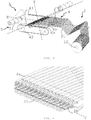
- these boards (8a, 8b) are initially parallel to the horizontal planes on which the warp yarns (21) arranged by the feeding assembly (2) are located, to subsequently taper in such a way as to foster the change of direction forced by the yarn-guide elements (7) of the warp yarns (21).
- said loom comprises a plurality of guide elements (7) for the warp yarns (21), whose yarn input ends rest on next to the terminal edges of each of said two boards (8a, 8b), whereas the yarn output ends are located downstream the latter.
- the input and output ends of the different guide elements (7) are aligned parallel to said weaving front F and comprise appropriate check means for said warp yarn (21).
- the guide elements (7) keep the warp yarns spaced to make it possible to place the oblique fixed weft internally to the two warp yarn surfaces before said yarn (51) is laid down.
- said guide elements (7) are static and shaped so as to present a convex section on the side facing the weaving front F. Said convex profile determines a slightly arched shape of the yarn guide (7), which enables the latter to rise or lower the warp yarns (21) to facilitate the insertion of the inserted oblique weft yarn (51).
- the yarn (51) can go through the gap determined by the guide elements (7) and cross both the warp yarns and those of the oblique fixed weft, thus originating a triaxial fabric.
- said guide elements (7) are arranged in such a way that said convex profile alternatively faces upwards or downwards, so that the yarn guide lowers or rises the warp yarn (21) sliding onto the outer section of said profile, respectively. Consequently, in the side views, every pair formed of successive elements forms an "X".
- said guide elements (7) present an opening between a first section and a second section featuring a convex profile, so as to enable the warp yarn (21) to cross the yarn guide surface, consequently the warp yarn moves internally to the yarn guide along the first section and externally along said second convex section.
- the loom comprises two parallel series of cuneiform stretchers (10), located before and after said weaving front F respectively, which develop an alternating movement in the vertical direction.
- the latter is temporally coordinated with the passage of the cursor (9) on the weaving front F.
- said stretchers (10) rise, said cursor (9) goes through and the stretchers consequently lower.
- the stretchers come between the yarns and stabilize, in particular, the oblique fixed weft yarn (41) and consequently foster the interweaving.
- the assembly (4) in charge of inserting the oblique fixed weft yarn (41) comprises a weft-placer cursor (46) which boustrophedonically places said yarn onto the side tracks (42, 43) of said assembly (4).
- Said weft-placer cursor (46) slides on a guide parallel to the already positioned weft and is fed by a reel located on cylinders (44, 45) onto which it rotates, thus unrolling without causing torsions onto the yarn.
- the side tracks (42, 43) drive along the X direction the oblique weft yarn directed along the Y direction, which generates, together with the X direction, a non-right angle.
- said reliefs (421, 431) which feature a substantially cylindrical shape, the oblique fixed weft yarn (41) is transmitted.
Landscapes
- Engineering & Computer Science (AREA)
- Textile Engineering (AREA)
- Looms (AREA)
- Braiding, Manufacturing Of Bobbin-Net Or Lace, And Manufacturing Of Nets By Knotting (AREA)
Claims (10)
- Machine à tisser pour tissu triaxial (1) comprenant :- un ensemble (2) d'alimentation de fils de chaîne (21), alignés en parallèle à une direction X, qui les dispose sur deux surfaces séparées l'une par rapport à l'autre ;- un ensemble (3) d'avancement de fils de chaîne (21) suivant la direction X ;- un ensemble (4) d'insertion du fil de trame fixe oblique (41), qui forme progressivement la trame fixe oblique entre lesdites deux surfaces des fils de chaîne, l'insertion et la rétraction étant alternées, c'est-à-dire en disposant boustrophedoniquement ledit fil (41) le long d'une direction Y qui est oblique par rapport à ladite direction X, tout en faisant avancer en même temps la trame oblique à peine formée parallèlement à la direction X ;- un ensemble (5) d'insertion du fil (51) de la trame oblique le long d'un front de tissage F, celui-ci étant oblique par rapport à la direction X ainsi qu'à la direction Y d'insertion de la trame fixe oblique (41) ; ledit ensemble (5) opérant d'une manière coordonnée avec ledit ensemble (4) d'insertion de la trame fixe oblique (41) ;caractérisée en ce qu'elle comprend une pluralité d'éléments de guide (7) des fils de chaîne (21), dont les extrémités d'entrée du fil sont alignées le long des bords extrêmes de chacun desdites deux surfaces des fils de chaîne (21) tandis que les extrémités de sortie des fils sont alignées parallèlement audit front de tissage F et en aval de celui-ci, de telle sorte à contribuer à garder les fils de chaîne (21) espacés l'un par rapport à l'autre pour permettre de disposer le fil de trame fixe oblique (41) à l'intérieur des deux groupes de fils de chaîne (21) avant que ledit fil de trame oblique (51) inséré soit posé, et en ce que lesdits éléments de guide (7) sont façonnés de telle sorte à présenter un profil convexe du côté regardant le front de tissage (F), lesdits éléments de guide (7) étant montés de telle sorte que ledit profil convexe regarde le haut ou le bas, de telle sorte que les éléments de guide (7) baissent ou lèvent le fil de chaîne (21), se déplaçant du côté extérieur dudit profil respectivement, tout en déplaçant également le fil de trame fixe oblique (41) déjà positionné entre les deux surfaces des fils de trame (41) déjà positionnés entre les deux surfaces des fils de chaîne et formant un passage à travers lequel le fil de trame oblique (51) est inséré, de telle sorte que ledit fil de trame oblique (51) inséré se croise alternativement avec les fils de chaîne (21) et ceux de la trame fixe oblique (41), de telle sorte à former un tissu triaxial.
- Machine à tisser selon la revendication précédente, caractérisée en ce que lesdits éléments de guide de fils (7) sont statiques.
- Machine à tisser selon une ou plusieurs des revendications précédentes, caractérisée en ce que lesdits éléments de guide présentent :- une extrémité d'entrée et une extrémité de sortie du fil de chaîne (21), toutes les deux comprenant des moyens appropriés de rétention dudit fil ;- une première section ;- une deuxième section convexe ;- une ouverture entre ladite première section planaire et ladite deuxième section convexe, de telle sorte à permettre au fil de chaîne (21) de traverser la surface du guide-fil de telle sorte que le fil de chaîne glisse à l'intérieur du guide-fil le long de la première section et à l'extérieur le long de ladite deuxième section convexe.
- Machine à tisser selon une ou plusieurs des revendications précédentes, caractérisée en ce qu'elle comprend deux tables (8a, 8b) chacune desquelles est interposée entre une desdites surfaces des fils de chaîne (21) et le fil fixe oblique et est adéquatement façonnée de telle sorte à réduire la distance entre ladite surface et le front de tissage F dans la direction d'avancement.
- Machine à tisser selon une ou plusieurs des revendications précédentes, caractérisée en ce qu'elle comprend deux séries parallèles d'élargisseurs cunéiformes (10), placés respectivement avant et après ledit front de tissage F, qui développent un mouvement alternatif en direction vertical, temporairement coordonné avec le passage le long du front de tissage F du fil de trame oblique (51) inséré ; chacun desdits élargisseurs s'interposant entre les fils de telle sorte à stabiliser temporairement la position dudit fil de trame fixe oblique (41) .
- Machine à tisser selon une ou plusieurs des revendications précédentes, caractérisée en ce que ledit ensemble (4) d'insertion du fil de trame fixe oblique (41) comprend deux chenilles latérales (42, 43) d'entraînement dudit fil de trame fixe oblique (41) disposé boustrophedoniquement suivant ladite direction d'avancement parallèle à ladite direction X.
- Machine à tisser selon la revendication précédente, caractérisée en ce que chacune desdites chenilles latérales (42, 43) peut être actionnée indépendamment l'une par rapport à l'autre, dans le but d'obtenir des effets de compactage du tissu (1).
- Machine à tisser selon une ou plusieurs des revendications précédentes, caractérisée en ce que ledit ensemble (3) d'avancement exploite l'action de traction exercée par l'enroulement de la pièce de tissu (1) déjà formée.
- Machine à tisser selon une ou plusieurs des revendications précédentes, caractérisée en ce que ledit ensemble (3) d'avancement comprend un ou plusieurs cylindres motorisés qui facilitent le défilement et le déroulement desdits fils de chaîne (21).
- Machine à tisser selon une ou plusieurs des revendications précédentes, caractérisée en ce que ledit ensemble (3) d'avancement comprend un ou plusieurs cylindres motorisés qui entraînent la pièce de tissu (1) déjà formée.
Applications Claiming Priority (2)
| Application Number | Priority Date | Filing Date | Title |
|---|---|---|---|
| IT000035A ITFI20130035A1 (it) | 2013-02-25 | 2013-02-25 | Telaio automatico per tessuti triassiali con varie tipologie di incroci. |
| PCT/IB2014/059241 WO2014128681A1 (fr) | 2013-02-25 | 2014-02-25 | Métier à tisser pour tissus triaxiaux avec dispositif de levée statique des fils de chaîne |
Publications (2)
| Publication Number | Publication Date |
|---|---|
| EP2959043A1 EP2959043A1 (fr) | 2015-12-30 |
| EP2959043B1 true EP2959043B1 (fr) | 2017-05-10 |
Family
ID=48145553
Family Applications (1)
| Application Number | Title | Priority Date | Filing Date |
|---|---|---|---|
| EP14714369.7A Active EP2959043B1 (fr) | 2013-02-25 | 2014-02-25 | Machine a tisser pour tissu triaxial avec dispositif statique pour la formation de la foule |
Country Status (3)
| Country | Link |
|---|---|
| EP (1) | EP2959043B1 (fr) |
| IT (1) | ITFI20130035A1 (fr) |
| WO (1) | WO2014128681A1 (fr) |
Families Citing this family (2)
| Publication number | Priority date | Publication date | Assignee | Title |
|---|---|---|---|---|
| CZ306561B6 (cs) * | 2015-09-17 | 2017-03-08 | VĂšTS, a.s. | Způsob vytváření tkaniny a zařízení k jeho provádění |
| CN108823746A (zh) * | 2018-07-12 | 2018-11-16 | 天津工大航泰复合材料有限公司 | 一种平面三向织物织造设备及方法 |
Family Cites Families (11)
| Publication number | Priority date | Publication date | Assignee | Title |
|---|---|---|---|---|
| US2985941A (en) | 1956-10-08 | 1961-05-30 | Minnesota Mining & Mfg | Woof fabric and method of making |
| GB1190214A (en) * | 1967-09-15 | 1970-04-29 | Rolls Royce | Method and Apparatus for Arranging a Weft Filament in a Sheet of Tows of Warp Filaments |
| US3446251A (en) | 1968-04-23 | 1969-05-27 | Gen Electric | Triaxial fabric |
| US3799209A (en) | 1972-04-19 | 1974-03-26 | Doweave Inc | Machine for forming triaxial fabrics |
| US3999578A (en) | 1975-08-11 | 1976-12-28 | Barber-Colman Company | Triaxial weaving machine with heddle shifting means and method |
| US4887656A (en) | 1986-06-20 | 1989-12-19 | Germain Verbauwhede | Woven fabric with bias weft and tire reinforced by same |
| FR2791365B1 (fr) * | 1999-03-22 | 2001-06-22 | Hexcel Fabrics | Tissu en biais, procede de fabrication et metier a tisser pour la fabrication en continu d'un tel tissu |
| US20040219855A1 (en) * | 2003-05-02 | 2004-11-04 | Tsotsis Thomas K. | Highly porous interlayers to toughen liquid-molded fabric-based composites |
| US20090272455A1 (en) * | 2005-12-23 | 2009-11-05 | Francisco Speich | Ribbon Needle Loom for Manufacturing a Strip, in Particular a Label Strip, Having a Woven-In Conductive Thread, in Particular Antenna Thread |
| GB0812738D0 (en) * | 2008-07-11 | 2008-08-20 | Griffith Textile Mach Ltd | Multi-axial fabric |
| DE102010007048A1 (de) * | 2010-02-06 | 2011-08-11 | Lindauer DORNIER Gesellschaft mit beschränkter Haftung, 88131 | Verfahren und Webmaschine zur Herstellung von Geweben mit Zusatzschusseffekten |
-
2013
- 2013-02-25 IT IT000035A patent/ITFI20130035A1/it unknown
-
2014
- 2014-02-25 EP EP14714369.7A patent/EP2959043B1/fr active Active
- 2014-02-25 WO PCT/IB2014/059241 patent/WO2014128681A1/fr not_active Ceased
Non-Patent Citations (1)
| Title |
|---|
| None * |
Also Published As
| Publication number | Publication date |
|---|---|
| WO2014128681A1 (fr) | 2014-08-28 |
| EP2959043A1 (fr) | 2015-12-30 |
| ITFI20130035A1 (it) | 2014-08-26 |
Similar Documents
| Publication | Publication Date | Title |
|---|---|---|
| CN105531410B (zh) | 用于编织3d织物的方法和装置、其3d织物物品及它们的用途 | |
| CN103459692B (zh) | 在两个倾斜取向上包含带条的纺织材料及其生产方法和装置 | |
| US6494235B1 (en) | Bias-bound fabric, method for making same and weaving machine for continuously making such a fabric | |
| JPS6392751A (ja) | 四軸織物及び四軸織機 | |
| EP2479324B1 (fr) | Procédé et moyens pour produire des matériaux textiles comprenant des bandes dans deux directions obliques | |
| US3818951A (en) | Loom | |
| US4841747A (en) | Warp-knitting machine, especially sewing-knitting machine, and method for the production of warp-knit fabric with oblique and diagonal filling threads | |
| RU2698730C2 (ru) | Двумерная ткань и способ ее получения | |
| Gandhi et al. | Technical fabric structures–1. Woven fabrics | |
| JP2018530679A (ja) | 多層織物および対応する製造方法 | |
| EP2959043B1 (fr) | Machine a tisser pour tissu triaxial avec dispositif statique pour la formation de la foule | |
| RU2474627C2 (ru) | Технологический процесс изготовления нераспускающегося трикотажного полотна | |
| Sondhelm | Technical fabric structures–1. Woven fabrics | |
| KR20170054786A (ko) | 코아 네트 직조장치 | |
| NO151669B (no) | Fremgangsmaate og anordning til aa forsyne arbeidsstedene i maskiner til fremstilling av flateaktig tekstilvare | |
| Majumdar | Principles of woven fabric manufacturing | |
| EP4488431A1 (fr) | Ourdissoir avec bobine à enroulement indépendant motorisé | |
| ITFI980083A1 (it) | Metodo ed apparecchiatura per la fabbricazione di manufatti tessili | |
| US3546044A (en) | Machine for making unwoven sheet material | |
| CN211112497U (zh) | 钩编机 | |
| US3500871A (en) | Guide arrangement for pick laying-in members | |
| JPH02293434A (ja) | 三軸織物及びその製造方法 | |
| JPH02191742A (ja) | 三次元織物及びその製造方法 | |
| JPS6215366A (ja) | 織物生地の製造方法及び装置 | |
| KR101172021B1 (ko) | 망지제직용 직기의 위사변형장치 |
Legal Events
| Date | Code | Title | Description |
|---|---|---|---|
| PUAI | Public reference made under article 153(3) epc to a published international application that has entered the european phase |
Free format text: ORIGINAL CODE: 0009012 |
|
| 17P | Request for examination filed |
Effective date: 20150821 |
|
| AK | Designated contracting states |
Kind code of ref document: A1 Designated state(s): AL AT BE BG CH CY CZ DE DK EE ES FI FR GB GR HR HU IE IS IT LI LT LU LV MC MK MT NL NO PL PT RO RS SE SI SK SM TR |
|
| AX | Request for extension of the european patent |
Extension state: BA ME |
|
| DAX | Request for extension of the european patent (deleted) | ||
| GRAP | Despatch of communication of intention to grant a patent |
Free format text: ORIGINAL CODE: EPIDOSNIGR1 |
|
| GRAJ | Information related to disapproval of communication of intention to grant by the applicant or resumption of examination proceedings by the epo deleted |
Free format text: ORIGINAL CODE: EPIDOSDIGR1 |
|
| GRAP | Despatch of communication of intention to grant a patent |
Free format text: ORIGINAL CODE: EPIDOSNIGR1 |
|
| INTG | Intention to grant announced |
Effective date: 20161024 |
|
| GRAS | Grant fee paid |
Free format text: ORIGINAL CODE: EPIDOSNIGR3 |
|
| GRAJ | Information related to disapproval of communication of intention to grant by the applicant or resumption of examination proceedings by the epo deleted |
Free format text: ORIGINAL CODE: EPIDOSDIGR1 |
|
| GRAL | Information related to payment of fee for publishing/printing deleted |
Free format text: ORIGINAL CODE: EPIDOSDIGR3 |
|
| INTC | Intention to grant announced (deleted) | ||
| RIN1 | Information on inventor provided before grant (corrected) |
Inventor name: BROGI, MARCO |
|
| GRAR | Information related to intention to grant a patent recorded |
Free format text: ORIGINAL CODE: EPIDOSNIGR71 |
|
| GRAA | (expected) grant |
Free format text: ORIGINAL CODE: 0009210 |
|
| RAP1 | Party data changed (applicant data changed or rights of an application transferred) |
Owner name: BROMAS-LOG S.R.L. |
|
| INTG | Intention to grant announced |
Effective date: 20170330 |
|
| AK | Designated contracting states |
Kind code of ref document: B1 Designated state(s): AL AT BE BG CH CY CZ DE DK EE ES FI FR GB GR HR HU IE IS IT LI LT LU LV MC MK MT NL NO PL PT RO RS SE SI SK SM TR |
|
| REG | Reference to a national code |
Ref country code: GB Ref legal event code: FG4D |
|
| REG | Reference to a national code |
Ref country code: AT Ref legal event code: REF Ref document number: 892430 Country of ref document: AT Kind code of ref document: T Effective date: 20170515 Ref country code: CH Ref legal event code: EP |
|
| REG | Reference to a national code |
Ref country code: IE Ref legal event code: FG4D |
|
| REG | Reference to a national code |
Ref country code: DE Ref legal event code: R096 Ref document number: 602014009679 Country of ref document: DE |
|
| REG | Reference to a national code |
Ref country code: NL Ref legal event code: MP Effective date: 20170510 |
|
| REG | Reference to a national code |
Ref country code: LT Ref legal event code: MG4D |
|
| REG | Reference to a national code |
Ref country code: AT Ref legal event code: MK05 Ref document number: 892430 Country of ref document: AT Kind code of ref document: T Effective date: 20170510 |
|
| PG25 | Lapsed in a contracting state [announced via postgrant information from national office to epo] |
Ref country code: LT Free format text: LAPSE BECAUSE OF FAILURE TO SUBMIT A TRANSLATION OF THE DESCRIPTION OR TO PAY THE FEE WITHIN THE PRESCRIBED TIME-LIMIT Effective date: 20170510 Ref country code: GR Free format text: LAPSE BECAUSE OF FAILURE TO SUBMIT A TRANSLATION OF THE DESCRIPTION OR TO PAY THE FEE WITHIN THE PRESCRIBED TIME-LIMIT Effective date: 20170811 Ref country code: HR Free format text: LAPSE BECAUSE OF FAILURE TO SUBMIT A TRANSLATION OF THE DESCRIPTION OR TO PAY THE FEE WITHIN THE PRESCRIBED TIME-LIMIT Effective date: 20170510 Ref country code: FI Free format text: LAPSE BECAUSE OF FAILURE TO SUBMIT A TRANSLATION OF THE DESCRIPTION OR TO PAY THE FEE WITHIN THE PRESCRIBED TIME-LIMIT Effective date: 20170510 Ref country code: AT Free format text: LAPSE BECAUSE OF FAILURE TO SUBMIT A TRANSLATION OF THE DESCRIPTION OR TO PAY THE FEE WITHIN THE PRESCRIBED TIME-LIMIT Effective date: 20170510 Ref country code: NO Free format text: LAPSE BECAUSE OF FAILURE TO SUBMIT A TRANSLATION OF THE DESCRIPTION OR TO PAY THE FEE WITHIN THE PRESCRIBED TIME-LIMIT Effective date: 20170810 Ref country code: ES Free format text: LAPSE BECAUSE OF FAILURE TO SUBMIT A TRANSLATION OF THE DESCRIPTION OR TO PAY THE FEE WITHIN THE PRESCRIBED TIME-LIMIT Effective date: 20170510 |
|
| PG25 | Lapsed in a contracting state [announced via postgrant information from national office to epo] |
Ref country code: IS Free format text: LAPSE BECAUSE OF FAILURE TO SUBMIT A TRANSLATION OF THE DESCRIPTION OR TO PAY THE FEE WITHIN THE PRESCRIBED TIME-LIMIT Effective date: 20170910 Ref country code: LV Free format text: LAPSE BECAUSE OF FAILURE TO SUBMIT A TRANSLATION OF THE DESCRIPTION OR TO PAY THE FEE WITHIN THE PRESCRIBED TIME-LIMIT Effective date: 20170510 Ref country code: RS Free format text: LAPSE BECAUSE OF FAILURE TO SUBMIT A TRANSLATION OF THE DESCRIPTION OR TO PAY THE FEE WITHIN THE PRESCRIBED TIME-LIMIT Effective date: 20170510 Ref country code: BG Free format text: LAPSE BECAUSE OF FAILURE TO SUBMIT A TRANSLATION OF THE DESCRIPTION OR TO PAY THE FEE WITHIN THE PRESCRIBED TIME-LIMIT Effective date: 20170810 Ref country code: PL Free format text: LAPSE BECAUSE OF FAILURE TO SUBMIT A TRANSLATION OF THE DESCRIPTION OR TO PAY THE FEE WITHIN THE PRESCRIBED TIME-LIMIT Effective date: 20170510 Ref country code: NL Free format text: LAPSE BECAUSE OF FAILURE TO SUBMIT A TRANSLATION OF THE DESCRIPTION OR TO PAY THE FEE WITHIN THE PRESCRIBED TIME-LIMIT Effective date: 20170510 Ref country code: SE Free format text: LAPSE BECAUSE OF FAILURE TO SUBMIT A TRANSLATION OF THE DESCRIPTION OR TO PAY THE FEE WITHIN THE PRESCRIBED TIME-LIMIT Effective date: 20170510 |
|
| REG | Reference to a national code |
Ref country code: FR Ref legal event code: PLFP Year of fee payment: 5 |
|
| PG25 | Lapsed in a contracting state [announced via postgrant information from national office to epo] |
Ref country code: CZ Free format text: LAPSE BECAUSE OF FAILURE TO SUBMIT A TRANSLATION OF THE DESCRIPTION OR TO PAY THE FEE WITHIN THE PRESCRIBED TIME-LIMIT Effective date: 20170510 Ref country code: EE Free format text: LAPSE BECAUSE OF FAILURE TO SUBMIT A TRANSLATION OF THE DESCRIPTION OR TO PAY THE FEE WITHIN THE PRESCRIBED TIME-LIMIT Effective date: 20170510 Ref country code: SK Free format text: LAPSE BECAUSE OF FAILURE TO SUBMIT A TRANSLATION OF THE DESCRIPTION OR TO PAY THE FEE WITHIN THE PRESCRIBED TIME-LIMIT Effective date: 20170510 Ref country code: RO Free format text: LAPSE BECAUSE OF FAILURE TO SUBMIT A TRANSLATION OF THE DESCRIPTION OR TO PAY THE FEE WITHIN THE PRESCRIBED TIME-LIMIT Effective date: 20170510 Ref country code: DK Free format text: LAPSE BECAUSE OF FAILURE TO SUBMIT A TRANSLATION OF THE DESCRIPTION OR TO PAY THE FEE WITHIN THE PRESCRIBED TIME-LIMIT Effective date: 20170510 |
|
| REG | Reference to a national code |
Ref country code: DE Ref legal event code: R097 Ref document number: 602014009679 Country of ref document: DE |
|
| PG25 | Lapsed in a contracting state [announced via postgrant information from national office to epo] |
Ref country code: SM Free format text: LAPSE BECAUSE OF FAILURE TO SUBMIT A TRANSLATION OF THE DESCRIPTION OR TO PAY THE FEE WITHIN THE PRESCRIBED TIME-LIMIT Effective date: 20170510 Ref country code: IT Free format text: LAPSE BECAUSE OF FAILURE TO SUBMIT A TRANSLATION OF THE DESCRIPTION OR TO PAY THE FEE WITHIN THE PRESCRIBED TIME-LIMIT Effective date: 20170510 |
|
| PLBE | No opposition filed within time limit |
Free format text: ORIGINAL CODE: 0009261 |
|
| STAA | Information on the status of an ep patent application or granted ep patent |
Free format text: STATUS: NO OPPOSITION FILED WITHIN TIME LIMIT |
|
| 26N | No opposition filed |
Effective date: 20180213 |
|
| PG25 | Lapsed in a contracting state [announced via postgrant information from national office to epo] |
Ref country code: SI Free format text: LAPSE BECAUSE OF FAILURE TO SUBMIT A TRANSLATION OF THE DESCRIPTION OR TO PAY THE FEE WITHIN THE PRESCRIBED TIME-LIMIT Effective date: 20170510 |
|
| REG | Reference to a national code |
Ref country code: CH Ref legal event code: PL |
|
| PG25 | Lapsed in a contracting state [announced via postgrant information from national office to epo] |
Ref country code: MC Free format text: LAPSE BECAUSE OF FAILURE TO SUBMIT A TRANSLATION OF THE DESCRIPTION OR TO PAY THE FEE WITHIN THE PRESCRIBED TIME-LIMIT Effective date: 20170510 |
|
| REG | Reference to a national code |
Ref country code: IE Ref legal event code: MM4A |
|
| REG | Reference to a national code |
Ref country code: BE Ref legal event code: MM Effective date: 20180228 |
|
| PG25 | Lapsed in a contracting state [announced via postgrant information from national office to epo] |
Ref country code: CH Free format text: LAPSE BECAUSE OF NON-PAYMENT OF DUE FEES Effective date: 20180228 Ref country code: LI Free format text: LAPSE BECAUSE OF NON-PAYMENT OF DUE FEES Effective date: 20180228 Ref country code: LU Free format text: LAPSE BECAUSE OF NON-PAYMENT OF DUE FEES Effective date: 20180225 |
|
| PG25 | Lapsed in a contracting state [announced via postgrant information from national office to epo] |
Ref country code: IE Free format text: LAPSE BECAUSE OF NON-PAYMENT OF DUE FEES Effective date: 20180225 |
|
| PG25 | Lapsed in a contracting state [announced via postgrant information from national office to epo] |
Ref country code: BE Free format text: LAPSE BECAUSE OF NON-PAYMENT OF DUE FEES Effective date: 20180228 |
|
| PG25 | Lapsed in a contracting state [announced via postgrant information from national office to epo] |
Ref country code: MT Free format text: LAPSE BECAUSE OF NON-PAYMENT OF DUE FEES Effective date: 20180225 |
|
| PG25 | Lapsed in a contracting state [announced via postgrant information from national office to epo] |
Ref country code: TR Free format text: LAPSE BECAUSE OF FAILURE TO SUBMIT A TRANSLATION OF THE DESCRIPTION OR TO PAY THE FEE WITHIN THE PRESCRIBED TIME-LIMIT Effective date: 20170510 |
|
| PG25 | Lapsed in a contracting state [announced via postgrant information from national office to epo] |
Ref country code: PT Free format text: LAPSE BECAUSE OF FAILURE TO SUBMIT A TRANSLATION OF THE DESCRIPTION OR TO PAY THE FEE WITHIN THE PRESCRIBED TIME-LIMIT Effective date: 20170510 |
|
| PG25 | Lapsed in a contracting state [announced via postgrant information from national office to epo] |
Ref country code: CY Free format text: LAPSE BECAUSE OF FAILURE TO SUBMIT A TRANSLATION OF THE DESCRIPTION OR TO PAY THE FEE WITHIN THE PRESCRIBED TIME-LIMIT Effective date: 20170510 Ref country code: MK Free format text: LAPSE BECAUSE OF NON-PAYMENT OF DUE FEES Effective date: 20170510 Ref country code: HU Free format text: LAPSE BECAUSE OF FAILURE TO SUBMIT A TRANSLATION OF THE DESCRIPTION OR TO PAY THE FEE WITHIN THE PRESCRIBED TIME-LIMIT; INVALID AB INITIO Effective date: 20140225 |
|
| PG25 | Lapsed in a contracting state [announced via postgrant information from national office to epo] |
Ref country code: AL Free format text: LAPSE BECAUSE OF FAILURE TO SUBMIT A TRANSLATION OF THE DESCRIPTION OR TO PAY THE FEE WITHIN THE PRESCRIBED TIME-LIMIT Effective date: 20170510 |
|
| PGFP | Annual fee paid to national office [announced via postgrant information from national office to epo] |
Ref country code: DE Payment date: 20250206 Year of fee payment: 12 |
|
| PGFP | Annual fee paid to national office [announced via postgrant information from national office to epo] |
Ref country code: FR Payment date: 20250205 Year of fee payment: 12 |
|
| PGFP | Annual fee paid to national office [announced via postgrant information from national office to epo] |
Ref country code: GB Payment date: 20250121 Year of fee payment: 12 |