EP2959111B1 - Revêtement isolant permettant des températures de fonctionnement supérieures - Google Patents
Revêtement isolant permettant des températures de fonctionnement supérieures Download PDFInfo
- Publication number
- EP2959111B1 EP2959111B1 EP13818916.2A EP13818916A EP2959111B1 EP 2959111 B1 EP2959111 B1 EP 2959111B1 EP 13818916 A EP13818916 A EP 13818916A EP 2959111 B1 EP2959111 B1 EP 2959111B1
- Authority
- EP
- European Patent Office
- Prior art keywords
- airfoil
- coat
- cooling
- component
- insulation
- Prior art date
- Legal status (The legal status is an assumption and is not a legal conclusion. Google has not performed a legal analysis and makes no representation as to the accuracy of the status listed.)
- Not-in-force
Links
- 238000000576 coating method Methods 0.000 title claims description 47
- 239000011248 coating agent Substances 0.000 title claims description 38
- 238000001816 cooling Methods 0.000 claims description 30
- 230000008646 thermal stress Effects 0.000 claims description 10
- 238000000034 method Methods 0.000 claims description 8
- 239000012720 thermal barrier coating Substances 0.000 claims description 7
- 239000011153 ceramic matrix composite Substances 0.000 claims description 5
- 230000000694 effects Effects 0.000 claims description 5
- 230000004888 barrier function Effects 0.000 claims description 4
- 230000007613 environmental effect Effects 0.000 claims description 4
- 238000005507 spraying Methods 0.000 claims description 4
- 230000002411 adverse Effects 0.000 claims description 3
- 230000001680 brushing effect Effects 0.000 claims description 3
- 238000007598 dipping method Methods 0.000 claims description 3
- 239000000758 substrate Substances 0.000 claims description 3
- 238000009413 insulation Methods 0.000 claims 8
- 239000012809 cooling fluid Substances 0.000 claims 3
- 239000000853 adhesive Substances 0.000 claims 1
- 230000001070 adhesive effect Effects 0.000 claims 1
- 238000000151 deposition Methods 0.000 claims 1
- 239000007789 gas Substances 0.000 description 11
- 239000000112 cooling gas Substances 0.000 description 9
- 239000000463 material Substances 0.000 description 4
- 239000002131 composite material Substances 0.000 description 3
- 239000002826 coolant Substances 0.000 description 2
- 230000008878 coupling Effects 0.000 description 2
- 238000010168 coupling process Methods 0.000 description 2
- 238000005859 coupling reaction Methods 0.000 description 2
- 238000012986 modification Methods 0.000 description 2
- 230000004048 modification Effects 0.000 description 2
- 230000004075 alteration Effects 0.000 description 1
- 238000013459 approach Methods 0.000 description 1
- 239000000567 combustion gas Substances 0.000 description 1
- 238000002485 combustion reaction Methods 0.000 description 1
- 239000000470 constituent Substances 0.000 description 1
- 230000001419 dependent effect Effects 0.000 description 1
- 238000005516 engineering process Methods 0.000 description 1
- 239000012530 fluid Substances 0.000 description 1
- 238000010438 heat treatment Methods 0.000 description 1
- 239000012212 insulator Substances 0.000 description 1
- -1 intermetallic Substances 0.000 description 1
- 239000002184 metal Substances 0.000 description 1
- 239000000203 mixture Substances 0.000 description 1
- NJPPVKZQTLUDBO-UHFFFAOYSA-N novaluron Chemical group C1=C(Cl)C(OC(F)(F)C(OC(F)(F)F)F)=CC=C1NC(=O)NC(=O)C1=C(F)C=CC=C1F NJPPVKZQTLUDBO-UHFFFAOYSA-N 0.000 description 1
- 230000001737 promoting effect Effects 0.000 description 1
- 230000035882 stress Effects 0.000 description 1
Images
Classifications
-
- F—MECHANICAL ENGINEERING; LIGHTING; HEATING; WEAPONS; BLASTING
- F01—MACHINES OR ENGINES IN GENERAL; ENGINE PLANTS IN GENERAL; STEAM ENGINES
- F01D—NON-POSITIVE DISPLACEMENT MACHINES OR ENGINES, e.g. STEAM TURBINES
- F01D5/00—Blades; Blade-carrying members; Heating, heat-insulating, cooling or antivibration means on the blades or the members
- F01D5/02—Blade-carrying members, e.g. rotors
- F01D5/08—Heating, heat-insulating or cooling means
-
- F—MECHANICAL ENGINEERING; LIGHTING; HEATING; WEAPONS; BLASTING
- F01—MACHINES OR ENGINES IN GENERAL; ENGINE PLANTS IN GENERAL; STEAM ENGINES
- F01D—NON-POSITIVE DISPLACEMENT MACHINES OR ENGINES, e.g. STEAM TURBINES
- F01D5/00—Blades; Blade-carrying members; Heating, heat-insulating, cooling or antivibration means on the blades or the members
- F01D5/12—Blades
- F01D5/14—Form or construction
- F01D5/18—Hollow blades, i.e. blades with cooling or heating channels or cavities; Heating, heat-insulating or cooling means on blades
- F01D5/187—Convection cooling
- F01D5/188—Convection cooling with an insert in the blade cavity to guide the cooling fluid, e.g. forming a separation wall
-
- F—MECHANICAL ENGINEERING; LIGHTING; HEATING; WEAPONS; BLASTING
- F01—MACHINES OR ENGINES IN GENERAL; ENGINE PLANTS IN GENERAL; STEAM ENGINES
- F01D—NON-POSITIVE DISPLACEMENT MACHINES OR ENGINES, e.g. STEAM TURBINES
- F01D25/00—Component parts, details, or accessories, not provided for in, or of interest apart from, other groups
- F01D25/08—Cooling; Heating; Heat-insulation
-
- F—MECHANICAL ENGINEERING; LIGHTING; HEATING; WEAPONS; BLASTING
- F01—MACHINES OR ENGINES IN GENERAL; ENGINE PLANTS IN GENERAL; STEAM ENGINES
- F01D—NON-POSITIVE DISPLACEMENT MACHINES OR ENGINES, e.g. STEAM TURBINES
- F01D5/00—Blades; Blade-carrying members; Heating, heat-insulating, cooling or antivibration means on the blades or the members
- F01D5/12—Blades
- F01D5/28—Selecting particular materials; Particular measures relating thereto; Measures against erosion or corrosion
- F01D5/284—Selection of ceramic materials
-
- F—MECHANICAL ENGINEERING; LIGHTING; HEATING; WEAPONS; BLASTING
- F01—MACHINES OR ENGINES IN GENERAL; ENGINE PLANTS IN GENERAL; STEAM ENGINES
- F01D—NON-POSITIVE DISPLACEMENT MACHINES OR ENGINES, e.g. STEAM TURBINES
- F01D5/00—Blades; Blade-carrying members; Heating, heat-insulating, cooling or antivibration means on the blades or the members
- F01D5/12—Blades
- F01D5/28—Selecting particular materials; Particular measures relating thereto; Measures against erosion or corrosion
- F01D5/288—Protective coatings for blades
-
- F—MECHANICAL ENGINEERING; LIGHTING; HEATING; WEAPONS; BLASTING
- F05—INDEXING SCHEMES RELATING TO ENGINES OR PUMPS IN VARIOUS SUBCLASSES OF CLASSES F01-F04
- F05D—INDEXING SCHEME FOR ASPECTS RELATING TO NON-POSITIVE-DISPLACEMENT MACHINES OR ENGINES, GAS-TURBINES OR JET-PROPULSION PLANTS
- F05D2230/00—Manufacture
- F05D2230/90—Coating; Surface treatment
-
- F—MECHANICAL ENGINEERING; LIGHTING; HEATING; WEAPONS; BLASTING
- F05—INDEXING SCHEMES RELATING TO ENGINES OR PUMPS IN VARIOUS SUBCLASSES OF CLASSES F01-F04
- F05D—INDEXING SCHEME FOR ASPECTS RELATING TO NON-POSITIVE-DISPLACEMENT MACHINES OR ENGINES, GAS-TURBINES OR JET-PROPULSION PLANTS
- F05D2260/00—Function
- F05D2260/20—Heat transfer, e.g. cooling
- F05D2260/231—Preventing heat transfer
-
- F—MECHANICAL ENGINEERING; LIGHTING; HEATING; WEAPONS; BLASTING
- F05—INDEXING SCHEMES RELATING TO ENGINES OR PUMPS IN VARIOUS SUBCLASSES OF CLASSES F01-F04
- F05D—INDEXING SCHEME FOR ASPECTS RELATING TO NON-POSITIVE-DISPLACEMENT MACHINES OR ENGINES, GAS-TURBINES OR JET-PROPULSION PLANTS
- F05D2300/00—Materials; Properties thereof
- F05D2300/60—Properties or characteristics given to material by treatment or manufacturing
- F05D2300/603—Composites; e.g. fibre-reinforced
- F05D2300/6033—Ceramic matrix composites [CMC]
-
- F—MECHANICAL ENGINEERING; LIGHTING; HEATING; WEAPONS; BLASTING
- F05—INDEXING SCHEMES RELATING TO ENGINES OR PUMPS IN VARIOUS SUBCLASSES OF CLASSES F01-F04
- F05D—INDEXING SCHEME FOR ASPECTS RELATING TO NON-POSITIVE-DISPLACEMENT MACHINES OR ENGINES, GAS-TURBINES OR JET-PROPULSION PLANTS
- F05D2300/00—Materials; Properties thereof
- F05D2300/60—Properties or characteristics given to material by treatment or manufacturing
- F05D2300/611—Coating
-
- Y—GENERAL TAGGING OF NEW TECHNOLOGICAL DEVELOPMENTS; GENERAL TAGGING OF CROSS-SECTIONAL TECHNOLOGIES SPANNING OVER SEVERAL SECTIONS OF THE IPC; TECHNICAL SUBJECTS COVERED BY FORMER USPC CROSS-REFERENCE ART COLLECTIONS [XRACs] AND DIGESTS
- Y02—TECHNOLOGIES OR APPLICATIONS FOR MITIGATION OR ADAPTATION AGAINST CLIMATE CHANGE
- Y02T—CLIMATE CHANGE MITIGATION TECHNOLOGIES RELATED TO TRANSPORTATION
- Y02T50/00—Aeronautics or air transport
- Y02T50/60—Efficient propulsion technologies, e.g. for aircraft
Definitions
- the application generally relates to protecting gas turbine engine components from thermal stresses, and particularly, but not exclusively, to the selective application of thermal barrier coatings or environmental barrier coatings to insulate gas turbine engine components from cooling effect to allow the components to run hotter than surrounding structure.
- US 2009/238,684 A1 discloses conductive surface coatings to ensure evening heating, thereby reducing thermal stress.
- US 6,533,547 B2 discloses a turbine blade with an internal space containing coolant fluid, coolant screens are provided on stiffening ribs to limit their rate of cooling and reduce thermal stress.
- US 2006/285973 A1 discloses a trailing edge attachment for composite turbine airfoils, which may include a spanwise cooling channel.
- the present disclosure comprises an apparatus as defined in claim 1 and a method as defined in claim 10.
- the present application provides for relatively high temperature gas turbine engine components that use coatings such as environmental barrier coatings (EBC) and thermal barrier coatings (TBC) as insulators so that the high temperature components maintain a relatively elevated temperature despite the presence of a cooling heat transfer.
- coatings can be applied over large areas of parts of the components, or can be selectively applied over smaller portions of the same parts.
- the coatings can be applied in areas where cooling by conduction, convective, or conductive effects such as through a cooling gas can lead to undesired thermal stresses. In one manner of operation such a protection acts to discourage the generation of adverse thermal stresses when the relatively high temperature components are located such as to be subject to impingement cooling if not protected by a coating such as an EBC or TBC.
- EBC environmental barrier coatings
- TBC thermal barrier coatings
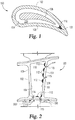
- an airfoil 100 of a gas turbine engine is provided in which is disposed an insulating coating useful to thermally protect the component from a cooling environment.
- the airfoil 100 may be a blade or a vane used in a turbomachinery component of a gas turbine engine.
- the airfoil 100 is provided with an airfoil wall 108 having an exterior surface 102 and an interior surface 104 that envelopes an interior hollow chamber 110.
- the interior hollow chamber 110 may house one or more internal support spars 106 and in some forms connecting structures between the spars 106 and the wall 108.
- the airfoil 100 may be made of a composite material such as, but not limited to, a ceramic matrix composite (CMC).
- the internal support spars 106 may be constructed from any suitable material including metal, intermetallic, composites, etc.
- the airfoil 100 is situated in a turbine of a gas turbine engine, such that the exterior surface 102 is exposed to a flow of hot combustion gases.
- a flow of cool or cooling gases 200 (arrows in Fig. 2 ) may be provided to flow through the interior hollow chamber 110 of the airfoil 100, such that the interior surface 104 is exposed to the flow of cool or cooling gases 200 that is at temperature cooler than that experienced by the exterior surface 102.
- This flow of cooling gases 200 is arranged in the illustrated embodiment to enter the interior hollow chamber 110 at a forward portion of the base of the airfoil 100 through one or more openings or inlets 114.
- Openings are also provided as outlets 115 along the length of the airfoil 100 and at an aft portion of the base of the airfoil 100. Additional inlets 114 and outlets 115 can be provided than those depicted in the illustrated embodiment. Alternative locations of the inlets 114 and outlets 115 are also contemplated as will be appreciated.
- the flow of cooling gases 200 may be provided for any variety of purposes such as cooling the support spars 106, delivering trailing edge film, or any number of other reasons readily apparent to one skilled in the art.
- a coating 112 may be selectively applied, for example, to areas where the cooling effect of these cooling gases is highest, which may be where the velocity of the cooling air is greatest relative to the rest of the flow path. For example, a part feature of the component, such as an interior surface of the airfoil 100, is exposed to the cooling flow, but only certain areas are treated to a coating so that thermal stresses are reduced to a desired level.
- Such areas where the cooling gas velocity is highest may be, for example, at openings 114, 115 through a component wall 108, or other narrowed passages in the flow path such as along the internal wall 104 at a trailing edge 101 of a airfoil 100.
- the coating 112 can be applied over a large area of the interior part of the airfoil 100, among other possibilities.
- This coating 112 can be a TBC and/or EBC in the illustrated embodiment, as well as any of the other embodiments described herein.
- the coating 112 can be adhered to the surface using any variety of approaches such as spraying, non-line of sight spraying, brushing, and dipping, to set forth just a few non-limiting embodiments.
- the techniques of applying the coating result in a broad area of fine small scale adhesion.
- the coating 112 can be applied to any variety of thicknesses and can include multiple layers of the same or different constituents.
- the application of the coating 112 can be confined to an entire part feature of a gas turbine engine component (e.g. the entirety of a hollow interior of the airfoil 100), or to a portion of that part feature (e.g. near the cooling holes of the airfoil 100).
- a part feature will be recognized to mean a particular, recognized part of a component.
- a blade has a suction side part, a pressure side part, a leading edge part, a trailing edge part. Blades that are cooled also have a cooling passage part, cooling passage pedestal part, etc.
- An integrated vane assembly includes vane parts, endwall part, etc.
- a combustor can include a liner part, a casing part, etc. Numerous other examples are also contemplated herein and need not be recited in detail given the general understanding in the art.
- a "part feature" is any feature that is recognized in the art as being associated with the component and is sometimes commonly referred to by those in the art to refer to parts for ease of convenience.
- the part feature is a cooling passage
- only a portion of the passage may be coated.
- Locations associated with the cooling passage that may be coated include the inlet to the cooling passage, where the inlet may be considered to be the inner surface of a passage closest to an opening from which the passage emerges, or it can also relate to the immediate area surrounding the opening such as that depicted in Fig. 2 .
- the coating can be selectively applied to certain areas by limiting the application reach of an instrument used to apply the coating. For example, where a coating is brushed through the use of a device having bristles, the device can be limited in the areas in which it applies the coating.
- the substrate upon which the coating is applied can be masked using any suitable device/material/etc.
- the selective coating aspects can be accomplished in number of manners resulting in a wide variety of coating applications/patterns/etc. associated with any given part feature.
- the selective coating aspect permits the coating to be applied differently (e.g. one selective coating applied via brushing, another selective coating applied via dipping, etc.) and alternatively and/or additional can be applied at different thicknesses, material compositions, etc.
- any variety of combinations of techniques, thicknesses, sizes, shapes, materials, can be used when determining particular selective coating applications.
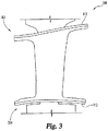
- FIG. 3 another non-limiting embodiment is disclosed in which an integrated vane and endwall 300 is shown having an application of coating 112 applied over the entire backside of endwalls 302 and 304.
- endwalls 302 and 304 include the coating 112, but other embodiments may include only one endwall with the coating.
- some embodiments may have one of the endwalls 302 and 304 with a coating applied over its entire surface while the other of the endwalls 302 and 304 may have selective coating(s) 112 applied as in any of the above embodiments.
- both endwalls 302 and 304 may have selective coating(s) 112.
- some embodiments of endwalls 302 and 304 may include a coating 112 applied as in any embodiment herein while the other of the endwalls 302 and 304 may not include any coating 112.
- the coating 112 on either or both endwalls 302 and 304 may be selectively applied to areas where a cooling effect is highest, for example an area where a velocity of a cooling air is greatest relative to the rest of the flow path. Such areas where the cooling gas velocity is highest may be, for example, at areas of nonuniform geometry, narrowed passages in the flow path, or in other areas where the cooling gases 200 are redirected.
- the Other embodiments can apply coatings 112 to components such as a combustor liner or bladetracks, among any number of other possible components in the gas turbine engine.
- Such coatings 112 can include any of the variations of type, size, placement, application method, etc. mentioned above.
Landscapes
- Engineering & Computer Science (AREA)
- Mechanical Engineering (AREA)
- General Engineering & Computer Science (AREA)
- Chemical & Material Sciences (AREA)
- Materials Engineering (AREA)
- Ceramic Engineering (AREA)
- Turbine Rotor Nozzle Sealing (AREA)
Claims (12)
- Appareil, comprenant : un composant de moteur à turbine à gaz comportant plusieurs structures constituantes et un revêtement d'isolation (112) adhérant à une première partie de l'une de la pluralité de structures constituantes pour former une fixation par adhésion à petite échelle, dans lequel ladite une des plusieurs structures constituantes inclut une deuxième partie exempte du revêtement isolant ;
caractérisé en ce que :
le composant de moteur à turbine à gaz est un composant composite à matrice céramique sous forme d'un composant de surface portante refroidie (100) comportant un intérieur ouvert (110) défini par une surface interne (104) du composant de surface portante refroidie et à travers lequel s'écoule un fluide de refroidissement (100), le revêtement isolant étant appliqué sur la surface interne au niveau d'un bord de fuite (01) de la surface portante. - Appareil selon la revendication 1, dans lequel le revêtement isolant est constitué par un revêtement formant barrière thermique ou un revêtement formant barrière environnementale.
- Appareil selon la revendication 1, dans lequel le composant de surface portante refroidie inclut une entrée de trou de refroidissement (114), et dans lequel l'intérieur ouvert (110) inclut l'entrée de trou de refroidissement (114), le revêtement isolant étant appliqué dans la zone de l'entrée de trou de refroidissement (114) de sorte que le transfert de chaleur entre un fluide de refroidissement (200) et le composant composite à matrice céramique est empêché dans la zone du trou de refroidissement par suite des propriétés isolantes du revêtement isolant.
- Appareil selon la revendication 1, dans lequel le composant de surface portante inclut un côté arrière exposé à un fluide de refroidissement (200) et dans lequel ladite une des plusieurs structures constituantes dans laquelle le revêtement isolant est appliqué est le côté arrière du composant de moteur à turbine à gaz.
- Appareil selon la revendication 1, comprenant en outre un longeron (106) agencé dans l'intérieur ouvert (110).
- Appareil selon la revendication 1, dans lequel le revêtement à adhésion (112) est positionné entre la surface de substrat de la surface interne (104) et l'intérieur ouvert (110), de sorte que le revêtement à adhésion (112) isole la surface interne (104) d'un effet de refroidissement produisant une contrainte thermique défavorable.
- Appareil selon la revendication 1, dans lequel le revêtement à adhésion (112) est appliqué sélectivement sur plusieurs emplacements distincts sur la surface interne (104).
- Appareil selon la revendication 7, dans lequel les plusieurs emplacements distincts sont confinés dans la structure constituante du composant de surface portante.
- Appareil selon la revendication 1, dans lequel la surface portante inclut une ouverture de trou de refroidissement (114) et dans lequel l'intérieur ouvert inclut l'entrée de trou de refroidissement (114), le revêtement isolant étant appliqué dans la zone de l'entrée de trou de refroidissement.
- Procédé, comprenant les étapes ci-dessous :fourniture d'un composant composite à matrice céramique sous forme d'un composant de surface portante refroidie ;identification d'une zone à contrainte thermique de la surface portante sur laquelle peut être appliqué un revêtement isolant adhésif pour isoler la surface portante et empêcher les contraintes thermiques défavorables ; etadhésion d'un revêtement isolant sur la zone à contrainte thermique en déposant le revêtement isolant sur la surface portante ;dans lequel le revêtement isolant est appliqué dans la zone de l'entrée de trou de refroidissement et sur la surface interne au niveau du bord de fuite de la surface portante.
- Procédé selon la revendication 10, dans lequel l'étape d'application du revêtement isolant inclut une pulvérisation, un brossage ou un trempage.
- Procédé selon la revendication 10, dans lequel :(i) l'application est effectuée dans une zone à refroidissement par impact de jet, par convection ou par conduction, et dans lequel l'étape d'application inclut le confinement positif de l'application du revêtement isolant sur une zone limitée de la surface portante par rapport à une zone plus grande sur laquelle le revêtement isolant peut être appliqué sans confiner positivement l'application ; ou(ii) dans lequel le revêtement isolant est un revêtement de barrière thermique ou un revêtement barrière environnementale, et dans lequel l'identification est effectuée de manière simultanée à l'application.
Applications Claiming Priority (2)
| Application Number | Priority Date | Filing Date | Title |
|---|---|---|---|
| US201361768448P | 2013-02-23 | 2013-02-23 | |
| PCT/US2013/076293 WO2014130151A1 (fr) | 2013-02-23 | 2013-12-18 | Revêtement isolant permettant des températures de fonctionnement supérieures |
Publications (2)
| Publication Number | Publication Date |
|---|---|
| EP2959111A1 EP2959111A1 (fr) | 2015-12-30 |
| EP2959111B1 true EP2959111B1 (fr) | 2019-06-12 |
Family
ID=49943551
Family Applications (1)
| Application Number | Title | Priority Date | Filing Date |
|---|---|---|---|
| EP13818916.2A Not-in-force EP2959111B1 (fr) | 2013-02-23 | 2013-12-18 | Revêtement isolant permettant des températures de fonctionnement supérieures |
Country Status (3)
| Country | Link |
|---|---|
| US (1) | US10240460B2 (fr) |
| EP (1) | EP2959111B1 (fr) |
| WO (1) | WO2014130151A1 (fr) |
Families Citing this family (11)
| Publication number | Priority date | Publication date | Assignee | Title |
|---|---|---|---|---|
| US9869183B2 (en) * | 2014-08-01 | 2018-01-16 | United Technologies Corporation | Thermal barrier coating inside cooling channels |
| US20170067365A1 (en) * | 2015-09-09 | 2017-03-09 | General Electric Company | Exhaust frame strut with cooling fins |
| US20190055849A1 (en) * | 2015-11-10 | 2019-02-21 | Siemens Aktiengesellschaft | Laminated airfoil for a gas turbine |
| WO2017142549A1 (fr) * | 2016-02-19 | 2017-08-24 | Siemens Aktiengesellschaft | Composant hybride doté de canaux de refroidissement et processus correspondant |
| US10519779B2 (en) * | 2016-03-16 | 2019-12-31 | General Electric Company | Radial CMC wall thickness variation for stress response |
| US11112556B2 (en) * | 2017-05-27 | 2021-09-07 | Nulite Lighting | Edge-lit lighting fixtures |
| KR102230700B1 (ko) * | 2017-09-12 | 2021-03-23 | 한국기계연구원 | 가스 터빈용 블레이드 |
| US10487672B2 (en) * | 2017-11-20 | 2019-11-26 | Rolls-Royce Corporation | Airfoil for a gas turbine engine having insulating materials |
| US11459899B2 (en) | 2018-03-23 | 2022-10-04 | Raytheon Technologies Corporation | Turbine component with a thin interior partition |
| CN111241686B (zh) * | 2020-01-15 | 2021-10-26 | 南京航空航天大学 | 一种高温氧化环境陶瓷基复合材料任意加卸载应力应变曲线预测方法 |
| US12077479B2 (en) | 2020-02-12 | 2024-09-03 | Rolls-Royce Corporation | Recession resistant intermediate layer for CMC vane |
Family Cites Families (21)
| Publication number | Priority date | Publication date | Assignee | Title |
|---|---|---|---|---|
| US5083422A (en) | 1988-03-25 | 1992-01-28 | General Electric Company | Method of breach cooling |
| US6393828B1 (en) * | 1997-07-21 | 2002-05-28 | General Electric Company | Protective coatings for turbine combustion components |
| JP4315599B2 (ja) | 1998-08-31 | 2009-08-19 | シーメンス アクチエンゲゼルシヤフト | タービン翼 |
| US6126400A (en) * | 1999-02-01 | 2000-10-03 | General Electric Company | Thermal barrier coating wrap for turbine airfoil |
| US6296447B1 (en) | 1999-08-11 | 2001-10-02 | General Electric Company | Gas turbine component having location-dependent protective coatings thereon |
| US6283714B1 (en) | 1999-08-11 | 2001-09-04 | General Electric Company | Protection of internal and external surfaces of gas turbine airfoils |
| US6526756B2 (en) | 2001-02-14 | 2003-03-04 | General Electric Company | Method and apparatus for enhancing heat transfer in a combustor liner for a gas turbine |
| US6709230B2 (en) * | 2002-05-31 | 2004-03-23 | Siemens Westinghouse Power Corporation | Ceramic matrix composite gas turbine vane |
| DE102004028672A1 (de) * | 2004-06-12 | 2006-01-05 | Mtu Aero Engines Gmbh | Verfahren zum Beschichten von Innenflächen hohler Gasturbinenschaufeln |
| US7217088B2 (en) | 2005-02-02 | 2007-05-15 | Siemens Power Generation, Inc. | Cooling fluid preheating system for an airfoil in a turbine engine |
| US7241107B2 (en) * | 2005-05-19 | 2007-07-10 | Spanks Jr William A | Gas turbine airfoil with adjustable cooling air flow passages |
| US7393183B2 (en) * | 2005-06-17 | 2008-07-01 | Siemens Power Generation, Inc. | Trailing edge attachment for composite airfoil |
| GB2429515B (en) * | 2005-08-11 | 2008-06-25 | Rolls Royce Plc | Cooling method and apparatus |
| US7481621B2 (en) | 2005-12-22 | 2009-01-27 | Siemens Energy, Inc. | Airfoil with heating source |
| FR2897355B1 (fr) * | 2006-02-16 | 2012-07-20 | Arkema | Copolymeres comportant des blocs polyamide et des blocs polyether, ayant des proprietes optiques et thermiques ameliorees |
| US7665960B2 (en) | 2006-08-10 | 2010-02-23 | United Technologies Corporation | Turbine shroud thermal distortion control |
| US7641440B2 (en) * | 2006-08-31 | 2010-01-05 | Siemens Energy, Inc. | Cooling arrangement for CMC components with thermally conductive layer |
| FR2921937B1 (fr) * | 2007-10-03 | 2009-12-04 | Snecma | Procede d'aluminisation en phase vapeur d'une piece metallique de turbomachine |
| US8292580B2 (en) * | 2008-09-18 | 2012-10-23 | Siemens Energy, Inc. | CMC vane assembly apparatus and method |
| US9156086B2 (en) * | 2010-06-07 | 2015-10-13 | Siemens Energy, Inc. | Multi-component assembly casting |
| US9527262B2 (en) * | 2012-09-28 | 2016-12-27 | General Electric Company | Layered arrangement, hot-gas path component, and process of producing a layered arrangement |
-
2013
- 2013-12-18 EP EP13818916.2A patent/EP2959111B1/fr not_active Not-in-force
- 2013-12-18 US US14/132,421 patent/US10240460B2/en active Active
- 2013-12-18 WO PCT/US2013/076293 patent/WO2014130151A1/fr not_active Ceased
Non-Patent Citations (1)
| Title |
|---|
| None * |
Also Published As
| Publication number | Publication date |
|---|---|
| US20150322795A1 (en) | 2015-11-12 |
| EP2959111A1 (fr) | 2015-12-30 |
| US10240460B2 (en) | 2019-03-26 |
| WO2014130151A1 (fr) | 2014-08-28 |
Similar Documents
| Publication | Publication Date | Title |
|---|---|---|
| EP2959111B1 (fr) | Revêtement isolant permettant des températures de fonctionnement supérieures | |
| US8801372B2 (en) | Turbine shroud thermal distortion control | |
| JP4494444B2 (ja) | 被覆タービン翼 | |
| US20090108134A1 (en) | Icing protection system and method for enhancing heat transfer | |
| US5279111A (en) | Gas turbine cooling | |
| US6126400A (en) | Thermal barrier coating wrap for turbine airfoil | |
| EP3093448B1 (fr) | Ensemble de virole de turbine thermiquement isolé | |
| CN100564809C (zh) | 用于翼型部的冷却系统 | |
| US20130195650A1 (en) | Gas Turbine Pattern Swirl Film Cooling | |
| US20130058787A1 (en) | Turbine airfoil | |
| US20200141247A1 (en) | Component for a turbine engine with a film hole | |
| EP3179043B1 (fr) | Composante de turbine avec passage de refroidissement incorporé dans le revêtement | |
| US20160123186A1 (en) | Shroud assembly for a turbine engine | |
| CN110725718A (zh) | 具有冷却孔的涡轮发动机的部件 | |
| US7980820B2 (en) | Turbine engine blade cooling | |
| CN104704203B (zh) | 涡轮叶片布置 | |
| US10844729B2 (en) | Turbine vane for gas turbine engine | |
| US20180135427A1 (en) | Airfoil with leading end hollow panel | |
| CA2905139C (fr) | Lame partiellement revetue | |
| EP3246519B1 (fr) | Composant refroidi activement | |
| US11092015B2 (en) | Airfoil with metallic shield |
Legal Events
| Date | Code | Title | Description |
|---|---|---|---|
| PUAI | Public reference made under article 153(3) epc to a published international application that has entered the european phase |
Free format text: ORIGINAL CODE: 0009012 |
|
| 17P | Request for examination filed |
Effective date: 20150731 |
|
| AK | Designated contracting states |
Kind code of ref document: A1 Designated state(s): AL AT BE BG CH CY CZ DE DK EE ES FI FR GB GR HR HU IE IS IT LI LT LU LV MC MK MT NL NO PL PT RO RS SE SI SK SM TR |
|
| AX | Request for extension of the european patent |
Extension state: BA ME |
|
| DAX | Request for extension of the european patent (deleted) | ||
| STAA | Information on the status of an ep patent application or granted ep patent |
Free format text: STATUS: EXAMINATION IS IN PROGRESS |
|
| 17Q | First examination report despatched |
Effective date: 20180718 |
|
| REG | Reference to a national code |
Ref country code: DE Ref legal event code: R079 Ref document number: 602013056608 Country of ref document: DE Free format text: PREVIOUS MAIN CLASS: F01D0005180000 Ipc: F01D0005080000 |
|
| RIC1 | Information provided on ipc code assigned before grant |
Ipc: F01D 25/08 20060101ALI20181219BHEP Ipc: F01D 5/28 20060101ALI20181219BHEP Ipc: F01D 5/08 20060101AFI20181219BHEP Ipc: F01D 25/28 20060101ALI20181219BHEP Ipc: F01D 5/18 20060101ALI20181219BHEP |
|
| GRAP | Despatch of communication of intention to grant a patent |
Free format text: ORIGINAL CODE: EPIDOSNIGR1 |
|
| STAA | Information on the status of an ep patent application or granted ep patent |
Free format text: STATUS: GRANT OF PATENT IS INTENDED |
|
| INTG | Intention to grant announced |
Effective date: 20190205 |
|
| GRAS | Grant fee paid |
Free format text: ORIGINAL CODE: EPIDOSNIGR3 |
|
| GRAA | (expected) grant |
Free format text: ORIGINAL CODE: 0009210 |
|
| STAA | Information on the status of an ep patent application or granted ep patent |
Free format text: STATUS: THE PATENT HAS BEEN GRANTED |
|
| AK | Designated contracting states |
Kind code of ref document: B1 Designated state(s): AL AT BE BG CH CY CZ DE DK EE ES FI FR GB GR HR HU IE IS IT LI LT LU LV MC MK MT NL NO PL PT RO RS SE SI SK SM TR |
|
| REG | Reference to a national code |
Ref country code: GB Ref legal event code: FG4D |
|
| REG | Reference to a national code |
Ref country code: CH Ref legal event code: EP |
|
| REG | Reference to a national code |
Ref country code: AT Ref legal event code: REF Ref document number: 1142775 Country of ref document: AT Kind code of ref document: T Effective date: 20190615 |
|
| REG | Reference to a national code |
Ref country code: DE Ref legal event code: R096 Ref document number: 602013056608 Country of ref document: DE |
|
| REG | Reference to a national code |
Ref country code: IE Ref legal event code: FG4D |
|
| REG | Reference to a national code |
Ref country code: NL Ref legal event code: MP Effective date: 20190612 |
|
| REG | Reference to a national code |
Ref country code: LT Ref legal event code: MG4D |
|
| PG25 | Lapsed in a contracting state [announced via postgrant information from national office to epo] |
Ref country code: AL Free format text: LAPSE BECAUSE OF FAILURE TO SUBMIT A TRANSLATION OF THE DESCRIPTION OR TO PAY THE FEE WITHIN THE PRESCRIBED TIME-LIMIT Effective date: 20190612 Ref country code: FI Free format text: LAPSE BECAUSE OF FAILURE TO SUBMIT A TRANSLATION OF THE DESCRIPTION OR TO PAY THE FEE WITHIN THE PRESCRIBED TIME-LIMIT Effective date: 20190612 Ref country code: LT Free format text: LAPSE BECAUSE OF FAILURE TO SUBMIT A TRANSLATION OF THE DESCRIPTION OR TO PAY THE FEE WITHIN THE PRESCRIBED TIME-LIMIT Effective date: 20190612 Ref country code: HR Free format text: LAPSE BECAUSE OF FAILURE TO SUBMIT A TRANSLATION OF THE DESCRIPTION OR TO PAY THE FEE WITHIN THE PRESCRIBED TIME-LIMIT Effective date: 20190612 Ref country code: NO Free format text: LAPSE BECAUSE OF FAILURE TO SUBMIT A TRANSLATION OF THE DESCRIPTION OR TO PAY THE FEE WITHIN THE PRESCRIBED TIME-LIMIT Effective date: 20190912 Ref country code: SE Free format text: LAPSE BECAUSE OF FAILURE TO SUBMIT A TRANSLATION OF THE DESCRIPTION OR TO PAY THE FEE WITHIN THE PRESCRIBED TIME-LIMIT Effective date: 20190612 |
|
| PG25 | Lapsed in a contracting state [announced via postgrant information from national office to epo] |
Ref country code: RS Free format text: LAPSE BECAUSE OF FAILURE TO SUBMIT A TRANSLATION OF THE DESCRIPTION OR TO PAY THE FEE WITHIN THE PRESCRIBED TIME-LIMIT Effective date: 20190612 Ref country code: LV Free format text: LAPSE BECAUSE OF FAILURE TO SUBMIT A TRANSLATION OF THE DESCRIPTION OR TO PAY THE FEE WITHIN THE PRESCRIBED TIME-LIMIT Effective date: 20190612 Ref country code: GR Free format text: LAPSE BECAUSE OF FAILURE TO SUBMIT A TRANSLATION OF THE DESCRIPTION OR TO PAY THE FEE WITHIN THE PRESCRIBED TIME-LIMIT Effective date: 20190913 Ref country code: BG Free format text: LAPSE BECAUSE OF FAILURE TO SUBMIT A TRANSLATION OF THE DESCRIPTION OR TO PAY THE FEE WITHIN THE PRESCRIBED TIME-LIMIT Effective date: 20190912 |
|
| REG | Reference to a national code |
Ref country code: AT Ref legal event code: MK05 Ref document number: 1142775 Country of ref document: AT Kind code of ref document: T Effective date: 20190612 |
|
| PG25 | Lapsed in a contracting state [announced via postgrant information from national office to epo] |
Ref country code: PT Free format text: LAPSE BECAUSE OF FAILURE TO SUBMIT A TRANSLATION OF THE DESCRIPTION OR TO PAY THE FEE WITHIN THE PRESCRIBED TIME-LIMIT Effective date: 20191014 Ref country code: NL Free format text: LAPSE BECAUSE OF FAILURE TO SUBMIT A TRANSLATION OF THE DESCRIPTION OR TO PAY THE FEE WITHIN THE PRESCRIBED TIME-LIMIT Effective date: 20190612 Ref country code: CZ Free format text: LAPSE BECAUSE OF FAILURE TO SUBMIT A TRANSLATION OF THE DESCRIPTION OR TO PAY THE FEE WITHIN THE PRESCRIBED TIME-LIMIT Effective date: 20190612 Ref country code: RO Free format text: LAPSE BECAUSE OF FAILURE TO SUBMIT A TRANSLATION OF THE DESCRIPTION OR TO PAY THE FEE WITHIN THE PRESCRIBED TIME-LIMIT Effective date: 20190612 Ref country code: SK Free format text: LAPSE BECAUSE OF FAILURE TO SUBMIT A TRANSLATION OF THE DESCRIPTION OR TO PAY THE FEE WITHIN THE PRESCRIBED TIME-LIMIT Effective date: 20190612 Ref country code: AT Free format text: LAPSE BECAUSE OF FAILURE TO SUBMIT A TRANSLATION OF THE DESCRIPTION OR TO PAY THE FEE WITHIN THE PRESCRIBED TIME-LIMIT Effective date: 20190612 Ref country code: EE Free format text: LAPSE BECAUSE OF FAILURE TO SUBMIT A TRANSLATION OF THE DESCRIPTION OR TO PAY THE FEE WITHIN THE PRESCRIBED TIME-LIMIT Effective date: 20190612 |
|
| PG25 | Lapsed in a contracting state [announced via postgrant information from national office to epo] |
Ref country code: ES Free format text: LAPSE BECAUSE OF FAILURE TO SUBMIT A TRANSLATION OF THE DESCRIPTION OR TO PAY THE FEE WITHIN THE PRESCRIBED TIME-LIMIT Effective date: 20190612 Ref country code: IS Free format text: LAPSE BECAUSE OF FAILURE TO SUBMIT A TRANSLATION OF THE DESCRIPTION OR TO PAY THE FEE WITHIN THE PRESCRIBED TIME-LIMIT Effective date: 20191012 Ref country code: SM Free format text: LAPSE BECAUSE OF FAILURE TO SUBMIT A TRANSLATION OF THE DESCRIPTION OR TO PAY THE FEE WITHIN THE PRESCRIBED TIME-LIMIT Effective date: 20190612 Ref country code: IT Free format text: LAPSE BECAUSE OF FAILURE TO SUBMIT A TRANSLATION OF THE DESCRIPTION OR TO PAY THE FEE WITHIN THE PRESCRIBED TIME-LIMIT Effective date: 20190612 |
|
| PGFP | Annual fee paid to national office [announced via postgrant information from national office to epo] |
Ref country code: FR Payment date: 20191226 Year of fee payment: 7 |
|
| REG | Reference to a national code |
Ref country code: DE Ref legal event code: R097 Ref document number: 602013056608 Country of ref document: DE |
|
| PG25 | Lapsed in a contracting state [announced via postgrant information from national office to epo] |
Ref country code: TR Free format text: LAPSE BECAUSE OF FAILURE TO SUBMIT A TRANSLATION OF THE DESCRIPTION OR TO PAY THE FEE WITHIN THE PRESCRIBED TIME-LIMIT Effective date: 20190612 |
|
| PLBE | No opposition filed within time limit |
Free format text: ORIGINAL CODE: 0009261 |
|
| STAA | Information on the status of an ep patent application or granted ep patent |
Free format text: STATUS: NO OPPOSITION FILED WITHIN TIME LIMIT |
|
| PG25 | Lapsed in a contracting state [announced via postgrant information from national office to epo] |
Ref country code: PL Free format text: LAPSE BECAUSE OF FAILURE TO SUBMIT A TRANSLATION OF THE DESCRIPTION OR TO PAY THE FEE WITHIN THE PRESCRIBED TIME-LIMIT Effective date: 20190612 Ref country code: DK Free format text: LAPSE BECAUSE OF FAILURE TO SUBMIT A TRANSLATION OF THE DESCRIPTION OR TO PAY THE FEE WITHIN THE PRESCRIBED TIME-LIMIT Effective date: 20190612 |
|
| PGFP | Annual fee paid to national office [announced via postgrant information from national office to epo] |
Ref country code: DE Payment date: 20191231 Year of fee payment: 7 |
|
| 26N | No opposition filed |
Effective date: 20200313 |
|
| PG25 | Lapsed in a contracting state [announced via postgrant information from national office to epo] |
Ref country code: IS Free format text: LAPSE BECAUSE OF FAILURE TO SUBMIT A TRANSLATION OF THE DESCRIPTION OR TO PAY THE FEE WITHIN THE PRESCRIBED TIME-LIMIT Effective date: 20200224 Ref country code: SI Free format text: LAPSE BECAUSE OF FAILURE TO SUBMIT A TRANSLATION OF THE DESCRIPTION OR TO PAY THE FEE WITHIN THE PRESCRIBED TIME-LIMIT Effective date: 20190612 |
|
| PG2D | Information on lapse in contracting state deleted |
Ref country code: IS |
|
| REG | Reference to a national code |
Ref country code: CH Ref legal event code: PL |
|
| REG | Reference to a national code |
Ref country code: BE Ref legal event code: MM Effective date: 20191231 |
|
| PG25 | Lapsed in a contracting state [announced via postgrant information from national office to epo] |
Ref country code: MC Free format text: LAPSE BECAUSE OF FAILURE TO SUBMIT A TRANSLATION OF THE DESCRIPTION OR TO PAY THE FEE WITHIN THE PRESCRIBED TIME-LIMIT Effective date: 20190612 |
|
| GBPC | Gb: european patent ceased through non-payment of renewal fee |
Effective date: 20191218 |
|
| PG25 | Lapsed in a contracting state [announced via postgrant information from national office to epo] |
Ref country code: IE Free format text: LAPSE BECAUSE OF NON-PAYMENT OF DUE FEES Effective date: 20191218 Ref country code: GB Free format text: LAPSE BECAUSE OF NON-PAYMENT OF DUE FEES Effective date: 20191218 Ref country code: LU Free format text: LAPSE BECAUSE OF NON-PAYMENT OF DUE FEES Effective date: 20191218 |
|
| PG25 | Lapsed in a contracting state [announced via postgrant information from national office to epo] |
Ref country code: LI Free format text: LAPSE BECAUSE OF NON-PAYMENT OF DUE FEES Effective date: 20191231 Ref country code: CH Free format text: LAPSE BECAUSE OF NON-PAYMENT OF DUE FEES Effective date: 20191231 Ref country code: BE Free format text: LAPSE BECAUSE OF NON-PAYMENT OF DUE FEES Effective date: 20191231 |
|
| PG25 | Lapsed in a contracting state [announced via postgrant information from national office to epo] |
Ref country code: CY Free format text: LAPSE BECAUSE OF FAILURE TO SUBMIT A TRANSLATION OF THE DESCRIPTION OR TO PAY THE FEE WITHIN THE PRESCRIBED TIME-LIMIT Effective date: 20190612 |
|
| REG | Reference to a national code |
Ref country code: DE Ref legal event code: R119 Ref document number: 602013056608 Country of ref document: DE |
|
| PG25 | Lapsed in a contracting state [announced via postgrant information from national office to epo] |
Ref country code: MT Free format text: LAPSE BECAUSE OF FAILURE TO SUBMIT A TRANSLATION OF THE DESCRIPTION OR TO PAY THE FEE WITHIN THE PRESCRIBED TIME-LIMIT Effective date: 20190612 Ref country code: HU Free format text: LAPSE BECAUSE OF FAILURE TO SUBMIT A TRANSLATION OF THE DESCRIPTION OR TO PAY THE FEE WITHIN THE PRESCRIBED TIME-LIMIT; INVALID AB INITIO Effective date: 20131218 |
|
| PG25 | Lapsed in a contracting state [announced via postgrant information from national office to epo] |
Ref country code: FR Free format text: LAPSE BECAUSE OF NON-PAYMENT OF DUE FEES Effective date: 20201231 |
|
| PG25 | Lapsed in a contracting state [announced via postgrant information from national office to epo] |
Ref country code: DE Free format text: LAPSE BECAUSE OF NON-PAYMENT OF DUE FEES Effective date: 20210701 |
|
| PG25 | Lapsed in a contracting state [announced via postgrant information from national office to epo] |
Ref country code: MK Free format text: LAPSE BECAUSE OF FAILURE TO SUBMIT A TRANSLATION OF THE DESCRIPTION OR TO PAY THE FEE WITHIN THE PRESCRIBED TIME-LIMIT Effective date: 20190612 |
|
| P01 | Opt-out of the competence of the unified patent court (upc) registered |
Effective date: 20230528 |