EP2959136B1 - Chambre de combustion de moteur à turbine à gaz avec rondelle à aillettes pour allumeur - Google Patents
Chambre de combustion de moteur à turbine à gaz avec rondelle à aillettes pour allumeur Download PDFInfo
- Publication number
- EP2959136B1 EP2959136B1 EP14753581.9A EP14753581A EP2959136B1 EP 2959136 B1 EP2959136 B1 EP 2959136B1 EP 14753581 A EP14753581 A EP 14753581A EP 2959136 B1 EP2959136 B1 EP 2959136B1
- Authority
- EP
- European Patent Office
- Prior art keywords
- combustor
- igniter
- gas turbine
- grommet
- turbine engine
- Prior art date
- Legal status (The legal status is an assumption and is not a legal conclusion. Google has not performed a legal analysis and makes no representation as to the accuracy of the status listed.)
- Active
Links
Images



Classifications
-
- F—MECHANICAL ENGINEERING; LIGHTING; HEATING; WEAPONS; BLASTING
- F02—COMBUSTION ENGINES; HOT-GAS OR COMBUSTION-PRODUCT ENGINE PLANTS
- F02C—GAS-TURBINE PLANTS; AIR INTAKES FOR JET-PROPULSION PLANTS; CONTROLLING FUEL SUPPLY IN AIR-BREATHING JET-PROPULSION PLANTS
- F02C7/00—Features, components parts, details or accessories, not provided for in, or of interest apart form groups F02C1/00 - F02C6/00; Air intakes for jet-propulsion plants
- F02C7/24—Heat or noise insulation
- F02C7/25—Fire protection or prevention
-
- F—MECHANICAL ENGINEERING; LIGHTING; HEATING; WEAPONS; BLASTING
- F23—COMBUSTION APPARATUS; COMBUSTION PROCESSES
- F23R—GENERATING COMBUSTION PRODUCTS OF HIGH PRESSURE OR HIGH VELOCITY, e.g. GAS-TURBINE COMBUSTION CHAMBERS
- F23R3/00—Continuous combustion chambers using liquid or gaseous fuel
- F23R3/002—Wall structures
-
- F—MECHANICAL ENGINEERING; LIGHTING; HEATING; WEAPONS; BLASTING
- F05—INDEXING SCHEMES RELATING TO ENGINES OR PUMPS IN VARIOUS SUBCLASSES OF CLASSES F01-F04
- F05D—INDEXING SCHEME FOR ASPECTS RELATING TO NON-POSITIVE-DISPLACEMENT MACHINES OR ENGINES, GAS-TURBINES OR JET-PROPULSION PLANTS
- F05D2220/00—Application
- F05D2220/30—Application in turbines
- F05D2220/32—Application in turbines in gas turbines
-
- F—MECHANICAL ENGINEERING; LIGHTING; HEATING; WEAPONS; BLASTING
- F05—INDEXING SCHEMES RELATING TO ENGINES OR PUMPS IN VARIOUS SUBCLASSES OF CLASSES F01-F04
- F05D—INDEXING SCHEME FOR ASPECTS RELATING TO NON-POSITIVE-DISPLACEMENT MACHINES OR ENGINES, GAS-TURBINES OR JET-PROPULSION PLANTS
- F05D2240/00—Components
- F05D2240/35—Combustors or associated equipment
-
- F—MECHANICAL ENGINEERING; LIGHTING; HEATING; WEAPONS; BLASTING
- F05—INDEXING SCHEMES RELATING TO ENGINES OR PUMPS IN VARIOUS SUBCLASSES OF CLASSES F01-F04
- F05D—INDEXING SCHEME FOR ASPECTS RELATING TO NON-POSITIVE-DISPLACEMENT MACHINES OR ENGINES, GAS-TURBINES OR JET-PROPULSION PLANTS
- F05D2260/00—Function
- F05D2260/20—Heat transfer, e.g. cooling
- F05D2260/231—Preventing heat transfer
-
- F—MECHANICAL ENGINEERING; LIGHTING; HEATING; WEAPONS; BLASTING
- F23—COMBUSTION APPARATUS; COMBUSTION PROCESSES
- F23R—GENERATING COMBUSTION PRODUCTS OF HIGH PRESSURE OR HIGH VELOCITY, e.g. GAS-TURBINE COMBUSTION CHAMBERS
- F23R2900/00—Special features of, or arrangements for continuous combustion chambers; Combustion processes therefor
- F23R2900/00004—Preventing formation of deposits on surfaces of gas turbine components, e.g. coke deposits
-
- F—MECHANICAL ENGINEERING; LIGHTING; HEATING; WEAPONS; BLASTING
- F23—COMBUSTION APPARATUS; COMBUSTION PROCESSES
- F23R—GENERATING COMBUSTION PRODUCTS OF HIGH PRESSURE OR HIGH VELOCITY, e.g. GAS-TURBINE COMBUSTION CHAMBERS
- F23R2900/00—Special features of, or arrangements for continuous combustion chambers; Combustion processes therefor
- F23R2900/00012—Details of sealing devices
-
- F—MECHANICAL ENGINEERING; LIGHTING; HEATING; WEAPONS; BLASTING
- F23—COMBUSTION APPARATUS; COMBUSTION PROCESSES
- F23R—GENERATING COMBUSTION PRODUCTS OF HIGH PRESSURE OR HIGH VELOCITY, e.g. GAS-TURBINE COMBUSTION CHAMBERS
- F23R2900/00—Special features of, or arrangements for continuous combustion chambers; Combustion processes therefor
- F23R2900/03042—Film cooled combustion chamber walls or domes
-
- F—MECHANICAL ENGINEERING; LIGHTING; HEATING; WEAPONS; BLASTING
- F23—COMBUSTION APPARATUS; COMBUSTION PROCESSES
- F23R—GENERATING COMBUSTION PRODUCTS OF HIGH PRESSURE OR HIGH VELOCITY, e.g. GAS-TURBINE COMBUSTION CHAMBERS
- F23R2900/00—Special features of, or arrangements for continuous combustion chambers; Combustion processes therefor
- F23R2900/03044—Impingement cooled combustion chamber walls or subassemblies
-
- F—MECHANICAL ENGINEERING; LIGHTING; HEATING; WEAPONS; BLASTING
- F23—COMBUSTION APPARATUS; COMBUSTION PROCESSES
- F23R—GENERATING COMBUSTION PRODUCTS OF HIGH PRESSURE OR HIGH VELOCITY, e.g. GAS-TURBINE COMBUSTION CHAMBERS
- F23R2900/00—Special features of, or arrangements for continuous combustion chambers; Combustion processes therefor
- F23R2900/03045—Convection cooled combustion chamber walls provided with turbolators or means for creating turbulences to increase cooling
-
- Y—GENERAL TAGGING OF NEW TECHNOLOGICAL DEVELOPMENTS; GENERAL TAGGING OF CROSS-SECTIONAL TECHNOLOGIES SPANNING OVER SEVERAL SECTIONS OF THE IPC; TECHNICAL SUBJECTS COVERED BY FORMER USPC CROSS-REFERENCE ART COLLECTIONS [XRACs] AND DIGESTS
- Y02—TECHNOLOGIES OR APPLICATIONS FOR MITIGATION OR ADAPTATION AGAINST CLIMATE CHANGE
- Y02T—CLIMATE CHANGE MITIGATION TECHNOLOGIES RELATED TO TRANSPORTATION
- Y02T50/00—Aeronautics or air transport
- Y02T50/60—Efficient propulsion technologies, e.g. for aircraft
Definitions
- the present disclosure relates to a gas turbine engine and, more particularly, to a cooling arrangement therefor.
- Gas turbine engines such as those that power modern commercial and military aircraft, generally include a compressor section to pressurize an airflow, a combustor section for burning a hydrocarbon fuel in the presence of the pressurized air, and a turbine section to extract energy from the resultant combustion gases.
- the combustor section is subject to high thermal loads for prolonged time periods and various cooling arrangements are provided. Among these are impingement cooling on a backside and film cooling on a gas side to maintain temperatures within material limits.
- EP 1424469 A discloses a prior art combustor as set forth in the preamble of claim 1.
- the rail extends approximately 240 degrees around the igniter aperture and the multiple of fins extend approximately 120 degrees around the igniter aperture.
- a further embodiment of any of the foregoing embodiments of the present disclosure further comprises an igniter that extends at least partially through the igniter aperture.
- FIG. 1 schematically illustrates a gas turbine engine 20.
- the gas turbine engine 20 is disclosed herein as a two-spool turbo fan that generally incorporates a fan section 22, a compressor section 24, a combustor section 26 and a turbine section 28.
- Alternative engines might include an augmentor section (not shown) among other systems or features.
- the fan section 22 drives air along a bypass flowpath while the compressor section 24 drives air along a core flowpath for compression and communication into the combustor section 26 then expansion through the turbine section 28.
- turbofan in the disclosed non-limiting embodiment, it should be understood that the concepts described herein are not limited to use with turbofans as the teachings may be applied to other types of turbine engines such as a turbojets, turboshafts, and three-spool (plus fan) turbofans wherein an intermediate spool includes an intermediate pressure compressor ("IPC") between a Low Pressure Compressor (“LPC”) and a High Pressure Compressor (“HPC”), and an intermediate pressure turbine (“IPT”) between the high pressure turbine (“HPT”) and the Low pressure Turbine (“LPT”).
- IPC intermediate pressure compressor
- LPC Low Pressure Compressor
- HPC High Pressure Compressor
- IPT intermediate pressure turbine
- the engine 20 generally includes a low spool 30 and a high spool 32 mounted for rotation about an engine central longitudinal axis A relative to an engine static structure 36 via several bearing structures 38.
- the low spool 30 generally includes an inner shaft 40 that interconnects a fan 42, a low pressure compressor 44 ("LPC") and a low pressure turbine 46 ("LPT").
- the inner shaft 40 drives the fan 42 directly or through a geared architecture 48 to drive the fan 42 at a lower speed than the low spool 30.
- An exemplary reduction transmission is an epicyclic transmission, namely a planetary or star gear system.
- the high spool 32 includes an outer shaft 50 that interconnects a high pressure compressor 52 ("HPC”) and high pressure turbine 54 ("HPT").
- a combustor 56 is arranged between the high pressure compressor 52 and the high pressure turbine 54.
- the inner shaft 40 and the outer shaft 50 are concentric and rotate about the engine central longitudinal axis A which is collinear with their longitudinal axes.
- the main engine shafts 40, 50 are supported at a plurality of points by bearing structures 38 within the static structure 36. It should be understood that various bearing structures 38 at various locations may alternatively or additionally be provided.
- the gas turbine engine 20 is a high-bypass geared aircraft engine.
- the gas turbine engine 20 bypass ratio is greater than about six (6:1).
- the geared architecture 48 can include an epicyclic gear train, such as a planetary gear system or other gear system.
- the example epicyclic gear train has a gear reduction ratio of greater than about 2.3:1, and in another example is greater than about 2.5:1.
- the geared turbofan enables operation of the low spool 30 at higher speeds which can increase the operational efficiency of the low pressure compressor 44 and low pressure turbine 46 and render increased pressure in a fewer number of stages.
- a pressure ratio associated with the LPT 46 is pressure measured prior to the inlet of the LPT 46 as related to the pressure at the outlet of the LPT 46 prior to an exhaust nozzle of the gas turbine engine 20.
- the bypass ratio of the gas turbine engine 20 is greater than about ten (10:1)
- the fan diameter is significantly larger than that of the low pressure compressor 44
- the low pressure turbine 46 has a pressure ratio that is greater than about five (5:1). It should be understood, however, that the above parameters are only exemplary of one embodiment of a geared architecture engine and that the present disclosure is applicable to other gas turbine engines including direct drive turbofans.
- a significant amount of thrust is provided by the bypass flow path due to the high bypass ratio.
- the fan section 22 of the gas turbine engine 20 is designed for a particular flight condition - typically cruise at about 0.8 Mach and about 35,000 feet (10,668 m). This flight condition, with the gas turbine engine 20 at its best fuel consumption, is also known as bucket cruise Thrust Specific Fuel Consumption (TSFC).
- TSFC Thrust Specific Fuel Consumption
- Fan Pressure Ratio is the pressure ratio across a blade of the fan section 22 without the use of a Fan Exit Guide Vane system.
- the low Fan Pressure Ratio according to one non-limiting embodiment of the example gas turbine engine 20 is less than 1.45.
- Low Corrected Fan Tip Speed is the actual fan tip speed divided by an industry standard temperature correction of ("Tram" / 518.7) 0.5 .
- the Low Corrected Fan Tip Speed according to one non-limiting embodiment of the example gas turbine engine 20 is less than about 1150 fps (351 m/s).
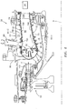
- the combustor 56 generally includes an outer combustor liner assembly 60, an inner combustor liner assembly 62 and a diffuser case module 64.
- the outer combustor liner assembly 60 and the inner combustor liner assembly 62 are spaced apart such that a combustion chamber 66 is defined therebetween.
- the combustion chamber 66 is generally annular in shape.
- the outer combustor liner assembly 60 is spaced radially inward from an outer diffuser case 64-O of the diffuser case module 64 to define an outer annular plenum 76.
- the inner combustor liner assembly 62 is spaced radially outward from an inner diffuser case 64-I of the diffuser case module 64 to define an inner annular plenum 78. It should be understood that although a particular combustor is illustrated, other combustor types with various combustor liner arrangements will also benefit herefrom. It should be further understood that the disclosed cooling flow paths are but an illustrated embodiment and should not be limited only thereto.
- the combustor liner assemblies 60, 62 contain the combustion products for direction toward the turbine section 28.
- Each combustor liner assembly 60, 62 generally includes a respective support shell 68, 70 which supports one or more heat shields 72, 74 mounted to a hot side of the respective support shell 68, 70.
- Each of the heat shields 72, 74 may be generally rectilinear and manufactured of, for example, a nickel based super alloy, ceramic or other temperature resistant material and are arranged to form a liner array.
- the liner array includes a multiple of forward heat shields 72A and a multiple of aft heat shields 72B that are circumferentially staggered to line the hot side of the outer support shell 68 (also shown in Figure 3 ).
- a multiple of forward heat shields 74A and a multiple of aft heat shields 74B are circumferentially staggered to line the hot side of the inner support shell 70 (also shown in Figure 3 ).
- the combustor 56 further includes a forward assembly 80 immediately downstream of the compressor section 24 to receive compressed airflow therefrom.
- the forward assembly 80 generally includes an annular hood 82, a bulkhead assembly 84, a multiple of fuel nozzles 86 (one shown) and a multiple of fuel nozzle guides 90 (one shown).
- Each of the fuel nozzle guides 90 is circumferentially aligned with one of the hood ports 94 to project through the bulkhead assembly 84.
- Each bulkhead assembly 84 includes a bulkhead support shell 96 secured to the combustor liner assemblies 60, 62, and a multiple of circumferentially distributed bulkhead heat shields 98 secured to the bulkhead support shell 96 around the central opening 92.
- the annular hood 82 extends radially between, and is secured to, the forwardmost ends of the combustor liner assemblies 60, 62.
- the annular hood 82 includes a multiple of circumferentially distributed hood ports 94 that accommodate the respective fuel nozzle 86 and introduce air into the forward end of the combustion chamber 66 through a central opening 92.
- Each fuel nozzle 86 may be secured to the diffuser case module 64 and project through one of the hood ports 94 and through the central opening 92 within the respective fuel nozzle guide 90.
- the forward assembly 80 introduces core combustion air into the forward section of the combustion chamber 66 while the remainder enters the outer annular plenum 76 and the inner annular plenum 78.
- the multiple of fuel nozzles 86 and adjacent structure generate a blended fuel-air mixture that supports stable combustion in the combustion chamber 66.
- Spark energy is provided to the combustor 56 through a frequency-pulsed igniter 88 (only one shown; illustrated schematically) that extends through at least one of the multiple of radially outward forward heat shields 72A.
- the igniter 88 such as a frequency-pulsed igniter provides a continuous spark or other ignition source.
- the igniter 88 may be located in a multiple of circumferential locations around the combustor 56 an in one or more outward forward heat shields 72A.
- the outer and inner support shells 68, 70 are mounted to a first row of Nozzle Guide Vanes (NGVs) 54A in the HPT 54.
- the NGVs 54A are static engine components which direct core airflow combustion gases onto the turbine blades of the first turbine rotor in the turbine section 28 to facilitate the conversion of pressure energy into kinetic energy.
- the core airflow combustion gases are also accelerated by the NGVs 54A because of their convergent shape and are typically given a "spin” or a "swirl” in the direction of turbine rotor rotation.
- the turbine rotor blades absorb this energy to drive the turbine rotor at high speed.
- a multiple of studs 100 extend from the heat shields 72, 74.
- the multiple of studs 100 mount the heat shields 72, 74 to the respective support shells 68, 70 with fasteners 102 such as nuts (also shown in Figure 5 ). That is, the studs 100 project rigidly from the heat shields 72, 74 and through the respective support shells 68, 70 to receive the fasteners 102 at a threaded distal end section thereof.
- a multiple of cooling impingement holes 104 penetrate through the support shells 68, 70 to allow air from the respective annular plenums 76, 78 to enter cavities 106A, 106B (also shown in Figure 5 ) formed in the combustor liner assemblies 60, 62 between the respective support shells 68, 70 and heat shields 72, 74.
- the cooling impingement holes 104 are generally normal to the surface of the heat shields 72, 74.
- the air in the cavities 106A, 106B provides backside impingement cooling of the heat shields 72, 74 that is generally defined herein as heat removal via internal convection.
- the geometry of the film holes, e.g, diameter, shape, density, surface angle, incidence angle, etc., as well as the location of the holes with respect to the high temperature main flow also contributes to effusion film cooling.
- the combination of cooling impingement holes 104 and cooling film holes 108 within the respective support shells 68, 70 and heat shields 72, 74 may often be referred to as an Impingement Film Floatliner assembly.
- the cooling film holes 108 allow the air to pass from the cavities 106A, 106B defined in part by a cold side 110 of the heat shields 72, 74 to a hot side 112 of the heat shields 72, 74 and thereby facilitate the formation of a film of cooling air along the hot side 112.
- the cooling film holes 108 are generally more numerous than the cooling impingement holes 104 to promote the development of a film cooling along the hot side 112 to sheath the heat shields 72, 74 on a combustion gas side.
- Film cooling as defined herein is the introduction of a relatively cooler airflow at one or more discrete locations along a surface exposed to a high temperature environment to protect that surface in the immediate region of the airflow injection as well as downstream thereof.
- a multiple of dilution apertures 116 penetrate through both the respective support shells 68, 70 and heat shields 72, 74 along a common axis D ( Figure 6 ).
- the dilution apertures 116 are located downstream of the forward assembly 80 to quench the combustion gases to supply cooling air into the combustor 56. It should be understood that other combustor types will also benefit herefrom.
- the igniter 88 ( Figure 2 ) is located though an igniter aperture 120 along an igniter axis I in the forward heat shield 72A.
- the igniter aperture 120 is surrounded by a grommet 122 that extends from the cold side 110.
- the grommet 122 contacts the respective support shell 68 to provide a seal therewith to at least partially define the cavity 106A.
- the combustion gases may slow towards the dilution apertures 116 and the igniter aperture 120 and may form stagnation points at the leading edges thereof.
- the stagnation points may form a heat source that may challenge the durability of the heat shields 72, 74 proximate this location.
- the hot combustion gases may also form a standing vortex that may also challenge the durability of the heat shields 72, 74 proximate this location.
- the grommet 122 includes a rail 124 that extends at least partially circumferentially around the igniter aperture 120 and a multiple of fins 126 that extend circumferentially for the remainder of the circumference.
- the rail 124 extends for approximately 240 degrees and the multiple of fins 126 extend for approximately 120 degrees.
- the multiple of fins 126 may be pins, pegs, protrusions, tabs, rectilinear blocks, or of other shapes. That is, the multiple of fins 126 may include various non-circumferentially continues rail geometries.
- the multiple of fins 126 facilitate airflow entry into the cavity 106A, 106B adjacent to the igniter 88 to purge the cavity of hot flow ingested from the combustor.
- the enhanced heat transfer is provided to the edge of the igniter aperture 120. This enhanced heat transfer occurs due to increased convective surface area provided by the multiple of fins 126.
- the multiple of fins 126 are located proximate the location where the durability of the heat shields 72, 74 may be challenged. In the disclosed non-limiting embodiment, the multiple of fins 126 are located where the fuel-air mixture swirl (illustrated schematically by arrow W in Figure 7 ) approaches an upstream edge of the igniter aperture 120 and generally continues to a downstream edge of the igniter aperture 120. Generally, the multiple of fins 126 extend for a circumferential distance less than approximately 50% of the total circumference around the igniter aperture 120. That is, the multiple of fins 126 provide a flowpath for cooling air and provide an increased surface area to the associated heat shields 72, 74. It should be appreciated that various circumferential extents and orientations may alternatively benefit herefrom.
- the multiple of fins 126 also increase oxidation life around the igniter aperture 120 and minimizes hot combustion gas ingestion into and around the igniter 88.
Landscapes
- Engineering & Computer Science (AREA)
- Chemical & Material Sciences (AREA)
- Combustion & Propulsion (AREA)
- Mechanical Engineering (AREA)
- General Engineering & Computer Science (AREA)
- Turbine Rotor Nozzle Sealing (AREA)
Claims (3)
- Chambre de combustion (56) d'un moteur à turbine à gaz (20) comprenant :une coque de support (68) ; etun bouclier thermique (72) monté sur la coque de support (68), le bouclier thermique (72) comprenant :caractérisée en ce que :un côté chaud (112) ; etun côté froid (110) opposé audit côté chaud (112), dans laquelle ledit côté froid (110) définit une rondelle (122) qui entoure une ouverture d'allumeur (120), et ladite rondelle (122) comporte une pluralité d'ailettes (126) et un rail (124) ;ladite rondelle (122) vient en contact avec la coque de support (68) pour assurer une étanchéité avec celle-ci ;ledit rail (124) s'étend uniquement partiellement autour d'une circonférence de ladite ouverture d'allumeur (120) et ladite pluralité d'ailettes (126) s'étendent uniquement pour le reste de ladite circonférence de ladite ouverture d'allumeur (120) ; etladite pluralité d'ailettes (126) sont des chevilles.
- Chambre de combustion (56) selon la revendication 1, dans laquelle ledit rail (124) s'étend à environ 240 degrés autour de ladite ouverture d'allumeur (120) et ladite pluralité d'ailettes (126) s'étendent à environ 120 degrés autour de ladite ouverture d'allumeur (120).
- Chambre de combustion (56) selon la revendication 1 ou 2, comprenant en outre un allumeur (88) qui s'étend au moins partiellement à travers ladite ouverture d'allumeur (120).
Applications Claiming Priority (2)
| Application Number | Priority Date | Filing Date | Title |
|---|---|---|---|
| US201361768950P | 2013-02-25 | 2013-02-25 | |
| PCT/US2014/018143 WO2014130978A1 (fr) | 2013-02-25 | 2014-02-25 | Rondelle à aillettes pour allumeur dans un moteur à turbine à gaz |
Publications (3)
| Publication Number | Publication Date |
|---|---|
| EP2959136A1 EP2959136A1 (fr) | 2015-12-30 |
| EP2959136A4 EP2959136A4 (fr) | 2016-11-09 |
| EP2959136B1 true EP2959136B1 (fr) | 2020-04-08 |
Family
ID=51391901
Family Applications (1)
| Application Number | Title | Priority Date | Filing Date |
|---|---|---|---|
| EP14753581.9A Active EP2959136B1 (fr) | 2013-02-25 | 2014-02-25 | Chambre de combustion de moteur à turbine à gaz avec rondelle à aillettes pour allumeur |
Country Status (3)
| Country | Link |
|---|---|
| US (1) | US10309314B2 (fr) |
| EP (1) | EP2959136B1 (fr) |
| WO (1) | WO2014130978A1 (fr) |
Families Citing this family (20)
| Publication number | Priority date | Publication date | Assignee | Title |
|---|---|---|---|---|
| DE102014206018A1 (de) * | 2014-03-31 | 2015-10-01 | Siemens Aktiengesellschaft | Gasturbinenanlage |
| US9746184B2 (en) | 2015-04-13 | 2017-08-29 | Pratt & Whitney Canada Corp. | Combustor dome heat shield |
| US10605169B2 (en) | 2017-04-18 | 2020-03-31 | United Technologies Corporation | Combustor panel cooling arrangements |
| US11098899B2 (en) | 2018-01-18 | 2021-08-24 | Raytheon Technologies Corporation | Panel burn through tolerant shell design |
| US11692488B2 (en) | 2020-11-04 | 2023-07-04 | Delavan Inc. | Torch igniter cooling system |
| US11473505B2 (en) | 2020-11-04 | 2022-10-18 | Delavan Inc. | Torch igniter cooling system |
| US11608783B2 (en) | 2020-11-04 | 2023-03-21 | Delavan, Inc. | Surface igniter cooling system |
| US11635027B2 (en) | 2020-11-18 | 2023-04-25 | Collins Engine Nozzles, Inc. | Fuel systems for torch ignition devices |
| US11226103B1 (en) * | 2020-12-16 | 2022-01-18 | Delavan Inc. | High-pressure continuous ignition device |
| US11421602B2 (en) | 2020-12-16 | 2022-08-23 | Delavan Inc. | Continuous ignition device exhaust manifold |
| US11486309B2 (en) | 2020-12-17 | 2022-11-01 | Delavan Inc. | Axially oriented internally mounted continuous ignition device: removable hot surface igniter |
| US11754289B2 (en) | 2020-12-17 | 2023-09-12 | Delavan, Inc. | Axially oriented internally mounted continuous ignition device: removable nozzle |
| US11635210B2 (en) | 2020-12-17 | 2023-04-25 | Collins Engine Nozzles, Inc. | Conformal and flexible woven heat shields for gas turbine engine components |
| US12092333B2 (en) | 2020-12-17 | 2024-09-17 | Collins Engine Nozzles, Inc. | Radially oriented internally mounted continuous ignition device |
| US11680528B2 (en) | 2020-12-18 | 2023-06-20 | Delavan Inc. | Internally-mounted torch igniters with removable igniter heads |
| US11209164B1 (en) | 2020-12-18 | 2021-12-28 | Delavan Inc. | Fuel injector systems for torch igniters |
| US11286862B1 (en) | 2020-12-18 | 2022-03-29 | Delavan Inc. | Torch injector systems for gas turbine combustors |
| CN116658932B (zh) | 2022-02-18 | 2025-09-16 | 通用电气公司 | 具有带旋流轮叶的稀释开口的燃烧器衬套 |
| CN117091160B (zh) | 2022-05-11 | 2026-04-21 | 通用电气公司 | 用于燃气涡轮的燃烧器的点火器外壳 |
| US12259133B2 (en) | 2023-02-15 | 2025-03-25 | Rtx Corporation | Cooling combustor wall boss |
Citations (2)
| Publication number | Priority date | Publication date | Assignee | Title |
|---|---|---|---|---|
| EP2527739A2 (fr) * | 2011-05-24 | 2012-11-28 | General Electric Company | Système et procédé pour le contrôle du débit dans un moteur à turbine à gaz |
| WO2014051871A1 (fr) * | 2012-09-25 | 2014-04-03 | United Technologies Corporation | Presse-étoupe de chemisage de chambre de combustion refroidi |
Family Cites Families (9)
| Publication number | Priority date | Publication date | Assignee | Title |
|---|---|---|---|---|
| US5419115A (en) * | 1994-04-29 | 1995-05-30 | United Technologies Corporation | Bulkhead and fuel nozzle guide assembly for an annular combustion chamber |
| DE19502328A1 (de) * | 1995-01-26 | 1996-08-01 | Bmw Rolls Royce Gmbh | Hitzeschild für eine Gasturbinen-Brennkammer |
| US6145319A (en) | 1998-07-16 | 2000-11-14 | General Electric Company | Transitional multihole combustion liner |
| US6557349B1 (en) | 2000-04-17 | 2003-05-06 | General Electric Company | Method and apparatus for increasing heat transfer from combustors |
| US7093439B2 (en) | 2002-05-16 | 2006-08-22 | United Technologies Corporation | Heat shield panels for use in a combustor for a gas turbine engine |
| GB0227842D0 (en) | 2002-11-29 | 2003-01-08 | Rolls Royce Plc | Sealing Arrangement |
| US7748221B2 (en) * | 2006-11-17 | 2010-07-06 | Pratt & Whitney Canada Corp. | Combustor heat shield with variable cooling |
| US20100212324A1 (en) * | 2009-02-26 | 2010-08-26 | Honeywell International Inc. | Dual walled combustors with impingement cooled igniters |
| FR2953908A1 (fr) * | 2009-12-16 | 2011-06-17 | Snecma | Guidage d'une bougie dans une chambre de combustion de turbomachine |
-
2014
- 2014-02-25 EP EP14753581.9A patent/EP2959136B1/fr active Active
- 2014-02-25 US US14/770,341 patent/US10309314B2/en active Active
- 2014-02-25 WO PCT/US2014/018143 patent/WO2014130978A1/fr not_active Ceased
Patent Citations (2)
| Publication number | Priority date | Publication date | Assignee | Title |
|---|---|---|---|---|
| EP2527739A2 (fr) * | 2011-05-24 | 2012-11-28 | General Electric Company | Système et procédé pour le contrôle du débit dans un moteur à turbine à gaz |
| WO2014051871A1 (fr) * | 2012-09-25 | 2014-04-03 | United Technologies Corporation | Presse-étoupe de chemisage de chambre de combustion refroidi |
Also Published As
| Publication number | Publication date |
|---|---|
| US20160010559A1 (en) | 2016-01-14 |
| EP2959136A4 (fr) | 2016-11-09 |
| US10309314B2 (en) | 2019-06-04 |
| WO2014130978A1 (fr) | 2014-08-28 |
| EP2959136A1 (fr) | 2015-12-30 |
Similar Documents
| Publication | Publication Date | Title |
|---|---|---|
| EP2959136B1 (fr) | Chambre de combustion de moteur à turbine à gaz avec rondelle à aillettes pour allumeur | |
| EP3366995B1 (fr) | Assemblage de panneau de chambre de combustion et procédé pour son refroidissement | |
| EP2984317B1 (fr) | Refroidissement de jonction en t de panneau de chambre de combustion | |
| EP2971668B1 (fr) | Refroidissement actif de bossages d'oeillet pour un panneau de chambre de combustion d'un moteur à turbine à gaz | |
| EP2946092B1 (fr) | Ensemble revêtement pour chambre de combustion de turbine à gaz équipé d'un profil hyperbolique convergent | |
| EP3077728B1 (fr) | Chambre de combustion de moteur à turbine à gaz ayant des passages d'effusion avec orientation de co-tourbillonnement, et procédé | |
| EP3047128B1 (fr) | Variation contrôlée de la chute de pression par refroidissement par effusion dans une chambre de combustion à double paroi d'une turbine à gaz | |
| EP2932070B1 (fr) | Bouclier thermique de chambre de combustion de moteur à turbine à gaz avec efficacité de refroidissement pelliculaire accrue | |
| EP2954261B1 (fr) | Chambre de combustion de turbine à gaz | |
| EP3667166A1 (fr) | Passage d'interface de refroidissement coudé de rail d'extrémité de panneau de chemise de chambre de combustion pour une chambre de combustion de turbine à gaz | |
| EP3008386B1 (fr) | Panneau de chemise de chambre de combustion pour moteur à turbine à gaz | |
| EP3008388A2 (fr) | Panneau de revêtement pour chambre de combustion de turbine à gaz | |
| US20150369487A1 (en) | Gas turbine engine component with upstream-directed cooling film holes | |
| EP3321587B1 (fr) | Interface non linéaire axial pour panneaux de chemise de chambre de combustion dans une chambre de combustion de turbine à gaz | |
| EP3084307B1 (fr) | Agencement de passage d'apport d'air pour chambre de combustion de moteur à turbine à gaz | |
| EP3321585B1 (fr) | Panneau de chemise de chambre de combustion non plane pour chambre de combustion de turbine à gaz |
Legal Events
| Date | Code | Title | Description |
|---|---|---|---|
| PUAI | Public reference made under article 153(3) epc to a published international application that has entered the european phase |
Free format text: ORIGINAL CODE: 0009012 |
|
| 17P | Request for examination filed |
Effective date: 20150924 |
|
| AK | Designated contracting states |
Kind code of ref document: A1 Designated state(s): AL AT BE BG CH CY CZ DE DK EE ES FI FR GB GR HR HU IE IS IT LI LT LU LV MC MK MT NL NO PL PT RO RS SE SI SK SM TR |
|
| AX | Request for extension of the european patent |
Extension state: BA ME |
|
| DAX | Request for extension of the european patent (deleted) | ||
| RAP1 | Party data changed (applicant data changed or rights of an application transferred) |
Owner name: UNITED TECHNOLOGIES CORPORATION |
|
| A4 | Supplementary search report drawn up and despatched |
Effective date: 20161007 |
|
| RIC1 | Information provided on ipc code assigned before grant |
Ipc: F02C 7/22 20060101ALI20161003BHEP Ipc: F02C 7/266 20060101AFI20161003BHEP |
|
| STAA | Information on the status of an ep patent application or granted ep patent |
Free format text: STATUS: EXAMINATION IS IN PROGRESS |
|
| 17Q | First examination report despatched |
Effective date: 20181115 |
|
| GRAP | Despatch of communication of intention to grant a patent |
Free format text: ORIGINAL CODE: EPIDOSNIGR1 |
|
| STAA | Information on the status of an ep patent application or granted ep patent |
Free format text: STATUS: GRANT OF PATENT IS INTENDED |
|
| RIC1 | Information provided on ipc code assigned before grant |
Ipc: F02C 7/22 20060101ALI20191004BHEP Ipc: F02C 7/266 20060101AFI20191004BHEP Ipc: F23R 3/00 20060101ALI20191004BHEP |
|
| INTG | Intention to grant announced |
Effective date: 20191023 |
|
| GRAS | Grant fee paid |
Free format text: ORIGINAL CODE: EPIDOSNIGR3 |
|
| GRAA | (expected) grant |
Free format text: ORIGINAL CODE: 0009210 |
|
| STAA | Information on the status of an ep patent application or granted ep patent |
Free format text: STATUS: THE PATENT HAS BEEN GRANTED |
|
| AK | Designated contracting states |
Kind code of ref document: B1 Designated state(s): AL AT BE BG CH CY CZ DE DK EE ES FI FR GB GR HR HU IE IS IT LI LT LU LV MC MK MT NL NO PL PT RO RS SE SI SK SM TR |
|
| REG | Reference to a national code |
Ref country code: AT Ref legal event code: REF Ref document number: 1254693 Country of ref document: AT Kind code of ref document: T Effective date: 20200415 Ref country code: CH Ref legal event code: EP |
|
| REG | Reference to a national code |
Ref country code: IE Ref legal event code: FG4D |
|
| REG | Reference to a national code |
Ref country code: DE Ref legal event code: R096 Ref document number: 602014063524 Country of ref document: DE |
|
| REG | Reference to a national code |
Ref country code: NL Ref legal event code: MP Effective date: 20200408 |
|
| REG | Reference to a national code |
Ref country code: LT Ref legal event code: MG4D |
|
| PG25 | Lapsed in a contracting state [announced via postgrant information from national office to epo] |
Ref country code: FI Free format text: LAPSE BECAUSE OF FAILURE TO SUBMIT A TRANSLATION OF THE DESCRIPTION OR TO PAY THE FEE WITHIN THE PRESCRIBED TIME-LIMIT Effective date: 20200408 Ref country code: IS Free format text: LAPSE BECAUSE OF FAILURE TO SUBMIT A TRANSLATION OF THE DESCRIPTION OR TO PAY THE FEE WITHIN THE PRESCRIBED TIME-LIMIT Effective date: 20200808 Ref country code: PT Free format text: LAPSE BECAUSE OF FAILURE TO SUBMIT A TRANSLATION OF THE DESCRIPTION OR TO PAY THE FEE WITHIN THE PRESCRIBED TIME-LIMIT Effective date: 20200817 Ref country code: GR Free format text: LAPSE BECAUSE OF FAILURE TO SUBMIT A TRANSLATION OF THE DESCRIPTION OR TO PAY THE FEE WITHIN THE PRESCRIBED TIME-LIMIT Effective date: 20200709 Ref country code: NO Free format text: LAPSE BECAUSE OF FAILURE TO SUBMIT A TRANSLATION OF THE DESCRIPTION OR TO PAY THE FEE WITHIN THE PRESCRIBED TIME-LIMIT Effective date: 20200708 Ref country code: SE Free format text: LAPSE BECAUSE OF FAILURE TO SUBMIT A TRANSLATION OF THE DESCRIPTION OR TO PAY THE FEE WITHIN THE PRESCRIBED TIME-LIMIT Effective date: 20200408 Ref country code: LT Free format text: LAPSE BECAUSE OF FAILURE TO SUBMIT A TRANSLATION OF THE DESCRIPTION OR TO PAY THE FEE WITHIN THE PRESCRIBED TIME-LIMIT Effective date: 20200408 Ref country code: NL Free format text: LAPSE BECAUSE OF FAILURE TO SUBMIT A TRANSLATION OF THE DESCRIPTION OR TO PAY THE FEE WITHIN THE PRESCRIBED TIME-LIMIT Effective date: 20200408 |
|
| REG | Reference to a national code |
Ref country code: AT Ref legal event code: MK05 Ref document number: 1254693 Country of ref document: AT Kind code of ref document: T Effective date: 20200408 |
|
| PG25 | Lapsed in a contracting state [announced via postgrant information from national office to epo] |
Ref country code: RS Free format text: LAPSE BECAUSE OF FAILURE TO SUBMIT A TRANSLATION OF THE DESCRIPTION OR TO PAY THE FEE WITHIN THE PRESCRIBED TIME-LIMIT Effective date: 20200408 Ref country code: BG Free format text: LAPSE BECAUSE OF FAILURE TO SUBMIT A TRANSLATION OF THE DESCRIPTION OR TO PAY THE FEE WITHIN THE PRESCRIBED TIME-LIMIT Effective date: 20200708 Ref country code: HR Free format text: LAPSE BECAUSE OF FAILURE TO SUBMIT A TRANSLATION OF THE DESCRIPTION OR TO PAY THE FEE WITHIN THE PRESCRIBED TIME-LIMIT Effective date: 20200408 Ref country code: LV Free format text: LAPSE BECAUSE OF FAILURE TO SUBMIT A TRANSLATION OF THE DESCRIPTION OR TO PAY THE FEE WITHIN THE PRESCRIBED TIME-LIMIT Effective date: 20200408 |
|
| PG25 | Lapsed in a contracting state [announced via postgrant information from national office to epo] |
Ref country code: AL Free format text: LAPSE BECAUSE OF FAILURE TO SUBMIT A TRANSLATION OF THE DESCRIPTION OR TO PAY THE FEE WITHIN THE PRESCRIBED TIME-LIMIT Effective date: 20200408 |
|
| REG | Reference to a national code |
Ref country code: DE Ref legal event code: R097 Ref document number: 602014063524 Country of ref document: DE |
|
| PG25 | Lapsed in a contracting state [announced via postgrant information from national office to epo] |
Ref country code: EE Free format text: LAPSE BECAUSE OF FAILURE TO SUBMIT A TRANSLATION OF THE DESCRIPTION OR TO PAY THE FEE WITHIN THE PRESCRIBED TIME-LIMIT Effective date: 20200408 Ref country code: AT Free format text: LAPSE BECAUSE OF FAILURE TO SUBMIT A TRANSLATION OF THE DESCRIPTION OR TO PAY THE FEE WITHIN THE PRESCRIBED TIME-LIMIT Effective date: 20200408 Ref country code: SM Free format text: LAPSE BECAUSE OF FAILURE TO SUBMIT A TRANSLATION OF THE DESCRIPTION OR TO PAY THE FEE WITHIN THE PRESCRIBED TIME-LIMIT Effective date: 20200408 Ref country code: ES Free format text: LAPSE BECAUSE OF FAILURE TO SUBMIT A TRANSLATION OF THE DESCRIPTION OR TO PAY THE FEE WITHIN THE PRESCRIBED TIME-LIMIT Effective date: 20200408 Ref country code: DK Free format text: LAPSE BECAUSE OF FAILURE TO SUBMIT A TRANSLATION OF THE DESCRIPTION OR TO PAY THE FEE WITHIN THE PRESCRIBED TIME-LIMIT Effective date: 20200408 Ref country code: CZ Free format text: LAPSE BECAUSE OF FAILURE TO SUBMIT A TRANSLATION OF THE DESCRIPTION OR TO PAY THE FEE WITHIN THE PRESCRIBED TIME-LIMIT Effective date: 20200408 Ref country code: RO Free format text: LAPSE BECAUSE OF FAILURE TO SUBMIT A TRANSLATION OF THE DESCRIPTION OR TO PAY THE FEE WITHIN THE PRESCRIBED TIME-LIMIT Effective date: 20200408 Ref country code: IT Free format text: LAPSE BECAUSE OF FAILURE TO SUBMIT A TRANSLATION OF THE DESCRIPTION OR TO PAY THE FEE WITHIN THE PRESCRIBED TIME-LIMIT Effective date: 20200408 |
|
| PLBE | No opposition filed within time limit |
Free format text: ORIGINAL CODE: 0009261 |
|
| STAA | Information on the status of an ep patent application or granted ep patent |
Free format text: STATUS: NO OPPOSITION FILED WITHIN TIME LIMIT |
|
| PG25 | Lapsed in a contracting state [announced via postgrant information from national office to epo] |
Ref country code: SK Free format text: LAPSE BECAUSE OF FAILURE TO SUBMIT A TRANSLATION OF THE DESCRIPTION OR TO PAY THE FEE WITHIN THE PRESCRIBED TIME-LIMIT Effective date: 20200408 Ref country code: PL Free format text: LAPSE BECAUSE OF FAILURE TO SUBMIT A TRANSLATION OF THE DESCRIPTION OR TO PAY THE FEE WITHIN THE PRESCRIBED TIME-LIMIT Effective date: 20200408 |
|
| 26N | No opposition filed |
Effective date: 20210112 |
|
| PG25 | Lapsed in a contracting state [announced via postgrant information from national office to epo] |
Ref country code: SI Free format text: LAPSE BECAUSE OF FAILURE TO SUBMIT A TRANSLATION OF THE DESCRIPTION OR TO PAY THE FEE WITHIN THE PRESCRIBED TIME-LIMIT Effective date: 20200408 |
|
| PG25 | Lapsed in a contracting state [announced via postgrant information from national office to epo] |
Ref country code: MC Free format text: LAPSE BECAUSE OF FAILURE TO SUBMIT A TRANSLATION OF THE DESCRIPTION OR TO PAY THE FEE WITHIN THE PRESCRIBED TIME-LIMIT Effective date: 20200408 |
|
| REG | Reference to a national code |
Ref country code: BE Ref legal event code: MM Effective date: 20210228 |
|
| PG25 | Lapsed in a contracting state [announced via postgrant information from national office to epo] |
Ref country code: LU Free format text: LAPSE BECAUSE OF NON-PAYMENT OF DUE FEES Effective date: 20210225 Ref country code: LI Free format text: LAPSE BECAUSE OF NON-PAYMENT OF DUE FEES Effective date: 20210228 Ref country code: CH Free format text: LAPSE BECAUSE OF NON-PAYMENT OF DUE FEES Effective date: 20210228 |
|
| PG25 | Lapsed in a contracting state [announced via postgrant information from national office to epo] |
Ref country code: IE Free format text: LAPSE BECAUSE OF NON-PAYMENT OF DUE FEES Effective date: 20210225 |
|
| PG25 | Lapsed in a contracting state [announced via postgrant information from national office to epo] |
Ref country code: BE Free format text: LAPSE BECAUSE OF NON-PAYMENT OF DUE FEES Effective date: 20210228 |
|
| REG | Reference to a national code |
Ref country code: DE Ref legal event code: R081 Ref document number: 602014063524 Country of ref document: DE Owner name: RAYTHEON TECHNOLOGIES CORPORATION (N.D.GES.D.S, US Free format text: FORMER OWNER: UNITED TECHNOLOGIES CORPORATION, FARMINGTON, CONN., US Ref country code: DE Ref legal event code: R081 Ref document number: 602014063524 Country of ref document: DE Owner name: RTX CORPORATION (N.D.GES.D. STAATES DELAWARE),, US Free format text: FORMER OWNER: UNITED TECHNOLOGIES CORPORATION, FARMINGTON, CONN., US |
|
| PG25 | Lapsed in a contracting state [announced via postgrant information from national office to epo] |
Ref country code: HU Free format text: LAPSE BECAUSE OF FAILURE TO SUBMIT A TRANSLATION OF THE DESCRIPTION OR TO PAY THE FEE WITHIN THE PRESCRIBED TIME-LIMIT; INVALID AB INITIO Effective date: 20140225 |
|
| P01 | Opt-out of the competence of the unified patent court (upc) registered |
Effective date: 20230520 |
|
| PG25 | Lapsed in a contracting state [announced via postgrant information from national office to epo] |
Ref country code: CY Free format text: LAPSE BECAUSE OF FAILURE TO SUBMIT A TRANSLATION OF THE DESCRIPTION OR TO PAY THE FEE WITHIN THE PRESCRIBED TIME-LIMIT Effective date: 20200408 |
|
| PG25 | Lapsed in a contracting state [announced via postgrant information from national office to epo] |
Ref country code: MK Free format text: LAPSE BECAUSE OF FAILURE TO SUBMIT A TRANSLATION OF THE DESCRIPTION OR TO PAY THE FEE WITHIN THE PRESCRIBED TIME-LIMIT Effective date: 20200408 |
|
| PG25 | Lapsed in a contracting state [announced via postgrant information from national office to epo] |
Ref country code: TR Free format text: LAPSE BECAUSE OF FAILURE TO SUBMIT A TRANSLATION OF THE DESCRIPTION OR TO PAY THE FEE WITHIN THE PRESCRIBED TIME-LIMIT Effective date: 20200408 |
|
| PG25 | Lapsed in a contracting state [announced via postgrant information from national office to epo] |
Ref country code: MT Free format text: LAPSE BECAUSE OF FAILURE TO SUBMIT A TRANSLATION OF THE DESCRIPTION OR TO PAY THE FEE WITHIN THE PRESCRIBED TIME-LIMIT Effective date: 20200408 |
|
| REG | Reference to a national code |
Ref country code: DE Ref legal event code: R081 Ref document number: 602014063524 Country of ref document: DE Owner name: RTX CORPORATION (N.D.GES.D. STAATES DELAWARE),, US Free format text: FORMER OWNER: RAYTHEON TECHNOLOGIES CORPORATION (N.D.GES.D.STAATES DELAWARE), ARLINGTON, VA, US |
|
| PGFP | Annual fee paid to national office [announced via postgrant information from national office to epo] |
Ref country code: GB Payment date: 20260122 Year of fee payment: 13 |
|
| PGFP | Annual fee paid to national office [announced via postgrant information from national office to epo] |
Ref country code: DE Payment date: 20260121 Year of fee payment: 13 |
|
| PGFP | Annual fee paid to national office [announced via postgrant information from national office to epo] |
Ref country code: FR Payment date: 20260121 Year of fee payment: 13 |