EP2959299B1 - Nanoparticules fluorescentes multicouches et leurs procédés de fabrication et d'utilisation - Google Patents
Nanoparticules fluorescentes multicouches et leurs procédés de fabrication et d'utilisation Download PDFInfo
- Publication number
- EP2959299B1 EP2959299B1 EP14754877.0A EP14754877A EP2959299B1 EP 2959299 B1 EP2959299 B1 EP 2959299B1 EP 14754877 A EP14754877 A EP 14754877A EP 2959299 B1 EP2959299 B1 EP 2959299B1
- Authority
- EP
- European Patent Office
- Prior art keywords
- frm
- silica
- dye
- nanoparticle
- layer
- Prior art date
- Legal status (The legal status is an assumption and is not a legal conclusion. Google has not performed a legal analysis and makes no representation as to the accuracy of the status listed.)
- Active
Links
Images







Classifications
-
- G—PHYSICS
- G01—MEASURING; TESTING
- G01N—INVESTIGATING OR ANALYSING MATERIALS BY DETERMINING THEIR CHEMICAL OR PHYSICAL PROPERTIES
- G01N33/00—Investigating or analysing materials by specific methods not covered by groups G01N1/00 - G01N31/00
- G01N33/48—Biological material, e.g. blood, urine; Haemocytometers
- G01N33/50—Chemical analysis of biological material, e.g. blood, urine; Testing involving biospecific ligand binding methods; Immunological testing
- G01N33/58—Chemical analysis of biological material, e.g. blood, urine; Testing involving biospecific ligand binding methods; Immunological testing involving labelled substances
- G01N33/585—Chemical analysis of biological material, e.g. blood, urine; Testing involving biospecific ligand binding methods; Immunological testing involving labelled substances with a particulate label, e.g. coloured latex
- G01N33/587—Nanoparticles
-
- B—PERFORMING OPERATIONS; TRANSPORTING
- B05—SPRAYING OR ATOMISING IN GENERAL; APPLYING FLUENT MATERIALS TO SURFACES, IN GENERAL
- B05D—PROCESSES FOR APPLYING FLUENT MATERIALS TO SURFACES, IN GENERAL
- B05D5/00—Processes for applying liquids or other fluent materials to surfaces to obtain special surface effects, finishes or structures
- B05D5/06—Processes for applying liquids or other fluent materials to surfaces to obtain special surface effects, finishes or structures to obtain multicolour or other optical effects
-
- C—CHEMISTRY; METALLURGY
- C09—DYES; PAINTS; POLISHES; NATURAL RESINS; ADHESIVES; COMPOSITIONS NOT OTHERWISE PROVIDED FOR; APPLICATIONS OF MATERIALS NOT OTHERWISE PROVIDED FOR
- C09B—ORGANIC DYES OR CLOSELY-RELATED COMPOUNDS FOR PRODUCING DYES, e.g. PIGMENTS; MORDANTS; LAKES
- C09B69/00—Dyes not provided for by a single group of this subclass
- C09B69/10—Polymeric dyes; Reaction products of dyes with monomers or with macromolecular compounds
-
- C—CHEMISTRY; METALLURGY
- C09—DYES; PAINTS; POLISHES; NATURAL RESINS; ADHESIVES; COMPOSITIONS NOT OTHERWISE PROVIDED FOR; APPLICATIONS OF MATERIALS NOT OTHERWISE PROVIDED FOR
- C09B—ORGANIC DYES OR CLOSELY-RELATED COMPOUNDS FOR PRODUCING DYES, e.g. PIGMENTS; MORDANTS; LAKES
- C09B69/00—Dyes not provided for by a single group of this subclass
- C09B69/10—Polymeric dyes; Reaction products of dyes with monomers or with macromolecular compounds
- C09B69/103—Polymeric dyes; Reaction products of dyes with monomers or with macromolecular compounds containing a diaryl- or triarylmethane dye
-
- C—CHEMISTRY; METALLURGY
- C09—DYES; PAINTS; POLISHES; NATURAL RESINS; ADHESIVES; COMPOSITIONS NOT OTHERWISE PROVIDED FOR; APPLICATIONS OF MATERIALS NOT OTHERWISE PROVIDED FOR
- C09B—ORGANIC DYES OR CLOSELY-RELATED COMPOUNDS FOR PRODUCING DYES, e.g. PIGMENTS; MORDANTS; LAKES
- C09B69/00—Dyes not provided for by a single group of this subclass
- C09B69/10—Polymeric dyes; Reaction products of dyes with monomers or with macromolecular compounds
- C09B69/105—Polymeric dyes; Reaction products of dyes with monomers or with macromolecular compounds containing a methine or polymethine dye
-
- G—PHYSICS
- G01—MEASURING; TESTING
- G01N—INVESTIGATING OR ANALYSING MATERIALS BY DETERMINING THEIR CHEMICAL OR PHYSICAL PROPERTIES
- G01N33/00—Investigating or analysing materials by specific methods not covered by groups G01N1/00 - G01N31/00
- G01N33/48—Biological material, e.g. blood, urine; Haemocytometers
- G01N33/50—Chemical analysis of biological material, e.g. blood, urine; Testing involving biospecific ligand binding methods; Immunological testing
- G01N33/53—Immunoassay; Biospecific binding assay; Materials therefor
- G01N33/543—Immunoassay; Biospecific binding assay; Materials therefor with an insoluble carrier for immobilising immunochemicals
- G01N33/54313—Immunoassay; Biospecific binding assay; Materials therefor with an insoluble carrier for immobilising immunochemicals the carrier being characterised by its particulate form
- G01N33/54346—Nanoparticles
-
- G—PHYSICS
- G01—MEASURING; TESTING
- G01N—INVESTIGATING OR ANALYSING MATERIALS BY DETERMINING THEIR CHEMICAL OR PHYSICAL PROPERTIES
- G01N33/00—Investigating or analysing materials by specific methods not covered by groups G01N1/00 - G01N31/00
- G01N33/48—Biological material, e.g. blood, urine; Haemocytometers
- G01N33/50—Chemical analysis of biological material, e.g. blood, urine; Testing involving biospecific ligand binding methods; Immunological testing
- G01N33/53—Immunoassay; Biospecific binding assay; Materials therefor
- G01N33/543—Immunoassay; Biospecific binding assay; Materials therefor with an insoluble carrier for immobilising immunochemicals
- G01N33/551—Immunoassay; Biospecific binding assay; Materials therefor with an insoluble carrier for immobilising immunochemicals the carrier being inorganic
- G01N33/552—Glass or silica
-
- G—PHYSICS
- G01—MEASURING; TESTING
- G01N—INVESTIGATING OR ANALYSING MATERIALS BY DETERMINING THEIR CHEMICAL OR PHYSICAL PROPERTIES
- G01N33/00—Investigating or analysing materials by specific methods not covered by groups G01N1/00 - G01N31/00
- G01N33/48—Biological material, e.g. blood, urine; Haemocytometers
- G01N33/50—Chemical analysis of biological material, e.g. blood, urine; Testing involving biospecific ligand binding methods; Immunological testing
- G01N33/58—Chemical analysis of biological material, e.g. blood, urine; Testing involving biospecific ligand binding methods; Immunological testing involving labelled substances
- G01N33/582—Chemical analysis of biological material, e.g. blood, urine; Testing involving biospecific ligand binding methods; Immunological testing involving labelled substances with fluorescent label
Definitions
- the present disclosure generally relates to layered fluorescently responsive material-containing nanoparticles. More particularly, the present disclosure relates to multilayer, fluorescently responsive material-containing silica nanoparticles.
- HTS high throughput screening
- Screening large libraries or biological multiplexing accelerates the development of tools for therapeutic and diagnostic applications.
- Biological multiplexing involves conducting multiple assays simultaneously without compromising on sensitivity and specificity.
- Advancement towards miniaturized HTS has led towards screening over thousands of compounds a day.
- Top to bottom two dimensional array fabrication technology has led to development of DNA chips, microarrays and bioMEMS. Positional encoding based pattern recognition has further helped identifying specific molecular finger prints.
- Dendrimer like DNA (DL-DNA) based fluorescent nanobarcodes were developed by precisely tagging the DL-DNA with two organic fluorophores in different ratios based on the number of available reactive sites. In order to amplify the fluorescence signal from these nanobarcodes, again microbeads were used as support for imaging and molecular detection. Similarly, 70 nm Forster resonance energy transfer (FRET) based silica nanoparticles encoding dyes with different dye ratios were synthesized and loaded on 10 ⁇ m streptavidin coated microspheres.
- FRET Forster resonance energy transfer
- multicolor fluorescent silica nanoparticles also referred to herein as multilayer, fluorescently responsive material (FRM)-containing nanoparticles, mcC dots, and tricolor C dots, and multicolor C dots
- FAM fluorescently responsive material
- the multicolor fluorescent silica nanoparticles may be referred to as bright multicolor fluorescent silica nanoparticles.
- the nanoparticles have sizes below 100 nm that contain two, three or more spectrally distinct dyes at two, three or more different intensity levels.
- the multicolor fluorescent silica nanoparticles can be used, for example, for intracellular bioimaging, high throughput screening and medical diagnostics.
- the silica nanoparticles contain the dyes N-(7-dimethylamino-4-methylcoumarin-3-yl) maleimide (DACm (blue)), tetramethylrhodamine-5-maleimide (TMRm (green)) and Cy5-maleimide (Cy5m (red)). These dyes are contained at three intensity levels per dye (no dye, low dye, or high dye).
- the particle architecture is designed so to control the number of dyes per color and to minimize energy transfer between dyes for maximum brightness. This combination of three dyes at three intensity levels results in the synthesis of twenty-six distinguishable particles based on wavelength and fluorescence intensity.
- Nanoparticles have one to three orders of magnitude in fluorescence brightness enhancement compared to free dyes.
- Nanoparticles with high dye loading were ⁇ 3.5-4 times brighter than particles with medium dye loaded particles. In this system moving from medium to high dye loadings by incorporating additional silica shells does not decrease the relative fluorescence emission of the nanoparticles.
- the methods of making multicolor fluorescent silica nanoparticles are carried out such that, e.g., dyes are added to a dye doped particle core in a layer-by-layer fashion and each spectrally distinct dye is spatially separated by a pure silica shell in order to reduce energy transfer between the dyes.
- the nanoparticles are synthesized such that the three dyes are added in a layer-by-layer fashion with green in the core followed by red in an inner shell followed by blue added as the final dye layer.
- Dye layers are spatially separated by thick enough silica shells to effectively suppress energy transfer between dye layers.
- each individual particle has onion-type structures with, for example, up to twenty-four distinct layers around a dyed core.
- the present disclosure provides multilayer, fluorescently responsive material (FRM)-containing nanoparticles. Also provided are methods of making and using the multilayer, FRM-containing nanoparticles.
- FRM fluorescently responsive material
- a multilayer, FRM-containing nanoparticle of the present disclosure provides a nanoparticle that can be uniquely identified by the specific FRM(s) and FRM level(s).
- the nanoparticles with built-in codes for identification can act as carriers and labels for molecules.
- the specific FHM(s)/level(s) combination (that may be described as an optical "bar code") can be identified by its fluorescence emission (e.g., in the form of an image).
- fluorescence emission e.g., in the form of an image.
- each distinguishable particle is analogous to a single well or array in the 2-D array technology.
- the nanoparticle architecture minimizes intralayer and interlayer quenching of the fluorescence from the FRM. This provides nanoparticles having a desirable brightness via effective use of all fluorescent dyes in the particles, resulting in desirable signal-to-noise levels in optical/fluorescence detection schemes.
- the present disclosure provides multilayer, FRM-containing silica nanoparticles.
- the nanoparticles comprise one or more fluorescently responsive materials (FRMs) which can be present at one or more amounts (i.e., levels).
- FRMs fluorescently responsive materials
- the nanoparticles can be from 5 nm to 500 nm, including all integer values and ranges therebetween, in size (e.g., diameter).
- Reference to multilayer, FRM-containing nanoparticle(s) herein is intended to include multilayer, dye-containing nanoparticle(s).
- Reference to FRM-free silica layer(s) herein is intended to include dye-free silica layer(s).
- Reference to FRM-containing silica layer(s) herein is intended to include dye-containing silica layer(s).
- Reference to outermost FRM-free silica layer(s) herein is intended to include outermost dye-containing silica layer(s).
- Reference to FRM herein is intended to include dye molecule(s).
- Reference to FRM-conjugate precursor(s) herein is intended to include dye-conjugate precursor(s).
- Reference to outermost FRM-containing silica layer(s) herein is intended to include outermost dye-containing silica layer(s).
- the nanoparticle comprises a silica core comprising a plurality of FRM molecules covalently bound to the silica network of the core, 1 to 100 FRM-containing silica layers, each layer comprising a plurality of FRM molecules covalently bound to the silica network of the FRM-containing silica layer, one or more FRM-free silica layers, wherein one of the FRM-free silica layers separates the silica core from one of the FRM-containing silica layers and, if present, each adjacent pair of the FRM-containing silica layers is separated by one of the FRM-free silica layers, an outermost FRM-free silica layer disposed on the outermost FRM-containing silica layer; and a plurality of poly(ethylene glycol) molecules covalently bound to the outer surface of the outermost FRM-free silica layer.
- the nanoparticle may further comprise one or more moieties (e.g., proteins, peptides, nucleic acids, aptamers, antibodies, antibody fragments, polymers, organic small molecules, and combinations thereof) covalently bound to the poly(ethylene glycol) molecules that are covalently bound to the outer surface of the outermost FRM-free silica layer.
- the nanoparticle can have a diameter of 5 nm to 500 nm, including all integer nm values and ranges therebetween.
- Each FRM-free silica layer has a thickness (e.g., 1 nm to 20 nm) such that there is less than 10% measurable energy transfer between the FRM in the core and in an adjacent FRM-containing silica layer or in adjacent FRM-containing silica layers.
- the nanoparticle comprises a silica core comprising a plurality of FRM molecules covalently bound to the silica network of the core, 1 to 100 FRM-containing silica layers, each layer comprising a plurality of FRM molecules covalently bound to the silica network of the FRM-containing silica layer, one or more FRM-free silica layers, wherein one of the FRM-free silica layers separates the silica core from one of the FRM-containing silica layers and, if present, each adjacent pair of the FRM-containing silica layers is separated by one of the FRM-free silica layers, and an outermost FRM-free silica layer disposed on the outermost FRM-containing silica layer.
- the nanoparticle can have a diameter of 5 nm to 500 nm, including all integer nm values and ranges therebetween.
- Each FRM-free silica layer has a thickness (e.g., 1 nm to 20 nm) such that there is less than 10% measurable energy transfer between the FRM in the core and in an adjacent FRM-containing silica layer or in adjacent FRM-containing silica layers.
- each of the FRM-free silica layers may be disposed on the silica core or an FRM-containing silica layer.
- the nanoparticle comprises a) a silica core comprising a plurality of FRM covalently bound to the silica network of the core; and b) alternating layers of FRM-free silica layers and FRM-containing layers surrounding the silica core, wherein a FRM-free silica layer surrounds the core.
- the outermost layer is an FRM-free silica layer or an FRM-containing layer.
- a plurality of polyether molecules are covalently bound the outer surface of the outermost FRM-free silica layer or FRM-containing layer.
- the core is substantially spherical in shape and can be from 1 nm to 20 nm, including all integer nm values therebetween, in size (e.g., diameter).
- the core has a plurality of fluorescently responsive material (e.g., fluorescently responsive molecules such as dye molecules and pigment molecules) that can be covalently bound to the silicon oxide network of the core.
- the FRM-free silica layer is disposed on the core and/or a FRM-containing silica layer. There is no detectible FRM in this layer.
- This layer at least partially covers the core and/or a FRM-containing silica layer.
- the layer is a continuous layer that completely covers the core and/or a FRM-containing silica layer.
- the nanoparticle can have from 1 to 99 FRM-free silica layers, including all integer numbers of layers and ranges therebetween.
- Each FRM-free silica layer isolates (i.e., reduces energy transfer between) the core and adjacent FRM-containing silica layer or adjacent FRM-containing silica layers.
- each FRM-free silica layer has a thickness such that there is 10% or less, 5% or less, 4% or less, 3% or less, 2% or less, or 1% or less measurable energy transfer between the FRM molecules in the core and in an adjacent FRM-containing silica layer or in adjacent FRM-containing silica layers.
- each FRM-free silica layer has a thickness such that there is no measurable energy transfer between the FRM in the core and adjacent FRM-containing silica layer or adjacent FRM-containing silica layers.
- Energy transfer between the FRM in the core and adjacent FRM-containing silica layer or adjacent FRM-containing silica layers can be measured by methods known in the art.
- energy transfer can be measured by Energy transfer can be measured by excitation of one FRM (e.g., one dye species) (donor) absorbing at lower wavelengths and examination of the emission of a second FRM (e.g., a second dye species) (acceptor) that has an overlap between its absorbance spectrum and the emission spectrum of the donor dye.
- a second method is to measure the emission intensity of the donor FRM (e.g., dye) in absence and presence of an acceptor FRM (e.g., dye). If FRET takes place between donor and acceptor, then the donor emission is suppressed.
- the FRM-free silica layer can be from 1 nm to 20 nm, including all integer nm values and ranges therebetween.
- the FRM-containing silica layer is disposed on a FRM-free silica layer. This layer at least partially covers the FRM-free silica layer. In an embodiment, the layer is a continuous layer that completely covers the core and/or a FRM-containing silica layer. In an embodiment, each FRM-free silica layer has a single type of FRM.
- the nanoparticle can have 1 to 100 FRM-containing silica layers, include all integer numbers of layers and ranges therebetween.
- the FRM-containing silica layer can have a thickness of less than 1 nm to 20 nm. In an embodiment, the FRM-containing silica layer has a thickness of 1 nm to 20 nm, including all integer nm values and ranges therebetween.
- the outermost FRM-free silica layer is disposed on the outermost FRM-containing silica layer. This layer at least partially covers the outermost FRM-containing silica layer. In an embodiment, the layer is a continuous layer that completely covers the core and/or a FRM-containing silica layer. This layer has a thickness of 1 nm to 20 nm, including all integer nm values and ranges therebetween.
- the core, FRM-containing silica layers, and FRM-free silica layers have a network structure.
- the network can be formed by condensation of a silica precursor.
- the network is a silica network.
- the silica network of the core can be formed by condensation of silica precursors such as, for example, TMOS and TEOS. Suitable precursors can be made using known methods and can be obtained from commercial sources.
- Any fluorescently responsive material e.g., dyes and pigments
- FRMs include dye molecules.
- Suitable fluorescently responsive materials can be made using known methods and can be obtained from commercial sources.
- a typical fluorophore is, for example, a fluorescent aromatic or heteroaromatic compound such as is a pyrene, an anthracene, a naphthalene, an acridine, a stilbene, an indole or benzindole, an oxazole or benzoxazole, a thiazole or benzothiazole, a 4-amino-7-nitrobenz-2-oxa-1,3-diazole (NBD), a cyanine, a carbocyanine, a carbostyryl, a porphyrin, a salicylate, an anthranilate, an azulene, a perylene, a pyridine, a quinoline, a coumarin (including hydroxycoumarins and aminocoumarins and fluorinated derivatives thereof), and like compounds, see for example U.S. Pat. Nos. 5,830,912 ; 4,774,339 ; 5,187,288 ;
- the dye is an organic dye.
- suitable organic dyes include, but are not xanthene derivatives (e.g., fluorescein, rhodamine, Oregon green, eosin, Texas red, and Cal Fluor dyes), cyanine derivatives (e.g., cyanine, indocarbocyanine, oxacarbocyanine, thiacarbocyanine, merocyanine, and Quasar dyes), naphthalene derivatives (e.g., dansyl and prodan derivatives), coumarin derivatives, oxadiazole derivatives (e.g., pyridyloxazole, nitrobenzoxadiazole and benzoxadiazole), pyrene derivatives (e.g., cascade blue), oxazine derivatives (e.g., Nile red, Nile blue, cresyl violet, oxazine 170), acridine derivatives (e.g., x
- the fluorescently responsive materials that have absorption and/or emission spectra that correspond to commonly used excitation and/detection wavelengths.
- the nanoparticle can have FRM with red, green, blue emission wavelengths, or a combination thereof.
- the fluorescently responsive materials are fluorescent dyes selected from N-(7-dimethylamino-4-methylcoumarin-3-yl) (DAC), tetramethylrhodamine-5-maleimide (TMR), Cy5, N-(7-dimethylamino-4-methylcoumarin-3 -yl)maleimide (DACm), tetramethylrhodamine-5 - maleimide (TMRm), Cy5-maleimide (Cy5m), or a combination thereof.
- DAC N-(7-dimethylamino-4-methylcoumarin-3-yl)
- TMR tetramethylrhodamine-5-maleimide
- TMRm tetramethylrhodamine-5 - maleimide
- Cy5m Cy5-maleimide
- the FRM is covalently bound (e.g., directly or via a linking group) to the nanoparticle silica network of the core or FRM-containing layer.
- the FRM can be covalently bound directly to the silica network via a linking group through, for example, an ester bond, amide bond, or thioether bond.
- a FRM e.g., dye molecule
- a sol-gel precursor e.g., a functionalized alkyl(trialkoxy)silane
- this FRM-conjugate precursor is used to produce the core or FRM-containing silica layer.
- the FRM is covalently bound to the silicon oxide network by a maleimide-mercapto conjugate.
- Covalent bond or bonds between the FRM and a sol-gel precursor e.g., a functionalized alkyl(trialkoxy)silane
- a sol-gel precursor e.g., a functionalized alkyl(trialkoxy)silane
- the FRM (e.g., dye molecules) in the nanoparticles i.e., covalently bound to the nanoparticle silica network of the core or FRM-containing layer
- fluorescence emission intensity i.e., brightness
- the fluorescence emission intensity of one or more or all the FRM (e.g., dye molecules) in the nanoparticle is 10%, 20%, 30%, 40%, 50%, 75%, 100%, two times, five times, 10 times, or 20 times greater than that of the free-FRM (e.g. dye molecules) when the fluorescence emission of each is measured in an aqueous solution.
- the outermost FRM-free silica layer may be passivated such that the nanoparticle is sterically stabilized against aggregation with other nanoparticles in physiological buffer solutions.
- the nanoparticle has a plurality of polymer groups, such as polyether groups covalently bound to the outer surface of the layer.
- Polyether groups can be derived from a polyether molecule or functionalized polyether molecule.
- the polyether group is a PEG group.
- the nanoparticle has a plurality of poly(ethylene glycol) (PEG) groups covalently bound to the outer surface of the layer.
- the PEG groups can be derived from a PEG molecule or functionalized PEG molecule.
- the PEG groups are covalently bound to the silica network of the layer.
- the PEG groups can have molecular weight of 400 g/mol to 10,000 g/mol.
- the PEG groups cover at least a portion of the outermost FRM-free silica layer. It is desirable that the PEG groups cover at least a portion of the layer such that the nanoparticles are sterically stabilized against aggregation in physiological buffer solutions.
- One or more of the PEG groups may have a moiety covalently bound to the group (i.e., PEG chain).
- all of the PEG groups have a moiety covalently bound to the PEG group (i.e., PEG chain).
- the nanoparticle can have all the same moiety or combinations of moieties.
- the moiety can be a targeting moiety that targets a cellular structure (e.g., a surface cellular structure or intracellular structure).
- moieties include, but are not limited to, proteins (e.g., protein subunits and protein domains), peptides, nucleic acids (e.g., single-stranded DNA molecules, double-stranded DNA molecules, single-stranded RNA molecules, double-stranded RNA molecules, and branched DNA molecules), aptamers (e.g,. DNA aptamers, RNA aptamers, and protein aptamers), antibodies, antibody fragments, polymers (e.g., dendrimers), organic small molecules (e.g., drug molecules and organic compounds such as folate or folic acid).
- proteins e.g., protein subunits and protein domains
- nucleic acids e.g., single-stranded DNA molecules, double-stranded DNA molecules, single-stranded RNA molecules, double-stranded RNA molecules, and branched DNA molecules
- aptamers e.g,. DNA aptamers, RNA aptamers, and protein apt
- the FRM (e.g., individual dyes) can be present in the nanoparticle at various amounts (i.e., levels).
- the FRM present in the nanoparticle is the sum of all the same type of FRM present in any of the core and FRM-containing silica layers.
- the amount (i.e., level) of FRM in a given nanoparticle can be expressed as the number of FRM (e.g., dye molecules) per nanoparticle. It is desirable that the amount of dye is such that the levels of the FRM in a nanoparticle can be distinguished from the levels of the same FRM in a different nanoparticle. The absence of the dye is considered a level.
- the amount of dye present in nanoparticles having the same nominal level of dye may vary.
- the amount of FRM in the nanoparticle is such that there is 10% or less, 5% or less, 4% or less, 3% or less, 2% or less, 1% or less overlap in the amount of the same FRM in another nanoparticle present (e.g., constituting another optical barcode). In an embodiment, the amount of FRM in the nanoparticle is such that there is no overlap in the amount of the same FRM in another nanoparticle present (e.g., constituting another optical barcode).
- the present disclosure provides a composition comprising the nanoparticles.
- the composition can comprise a plurality of distinguishable (i.e., uniquely identifiable) nanoparticles.
- the composition comprises a plurality of nanoparticles.
- composition comprises a plurality of nanoparticles having different combinations of dyes and/or levels of dyes.
- each of the plurality of nanoparticles has two or three dyes (e.g., N-(7-dimethylamino-4-methylcoumarin-3-yl) (DAC), tetramethylrhodamine-5-maleimide (TMR), Cy5) at a level of 0, 5, or 20 dyes per nanoparticle.
- DAC N-(7-dimethylamino-4-methylcoumarin-3-yl)
- TMR tetramethylrhodamine-5-maleimide
- Cy5 tetramethylrhodamine-5-maleimide
- the present disclosure provides methods of making the multilayer, FRM-containing nanoparticles.
- the nanoparticle is formed by layer-by-layer addition of FRM-free silica layers and FRM-containing silica layers to a core.
- a method of making a multilayer, FRM-containing nanoparticle comprises the steps of: a) contacting a silica precursor, a plurality of a single type of FRM conjugate precursor, a solvent, and base such that a silica core having a plurality of FRM is conjugated to the silica network of the silica core are formed, b) contacting the material from step a) with a silica precursor and a solvent such that a FRM-free silica layer is formed on the silica core, c) contacting the material from b) with a silica precursor, a single type of FRM conjugate precursor, a solvent, and base such that a FRM-containing silica layer is formed, contacting the material from b) with a silica precursor, a single type of FRM conjugate precursor, a solvent, and base such that a FRM-containing silica layer is formed, contacting the material from b) with a silica precursor, a single type of
- a method of making a multilayer, FRM-containing nanoparticle comprises the steps of: a) contacting a silica precursor, a plurality of a single type of FRM conjugate precursor, a solvent, and base such that a silica core having a plurality of FRM is conjugated to the silica network of the silica core are formed, b) contacting the material from step a) with a silica precursor and a solvent such that a FRM-free silica layer is formed on the silica core, c) contacting the material from b) with a silica precursor, a single type of FRM conjugate precursor, a solvent, and base such that a FRM-containing silica layer is formed, contacting the material from b) with a silica precursor, a single type of FRM conjugate precursor, a solvent, and base such that a FRM-containing silica layer is formed, contacting the material from b) with a silica precursor, a single type of
- the solvents, bases, FRM conjugate precursors, and silica precursors can be any species disclosed herein.
- the solvents, bases, FRM conjugate precursors, and silica precursors can be the same for each contacting step or may be different for one or more of the contacting steps.
- the silica precursor undergoes a reaction (such as a condensation reaction) to form a silica network.
- a reaction such as a condensation reaction
- the silica precursor can tetramethoxysilane (TMOS) or tetraethoxysilane (TEOS).
- TMOS tetramethoxysilane
- TEOS tetraethoxysilane
- the precursors can be made using methods known in the art or obtained from commercial sources.
- the FRM conjugate precursor is a FRM covalently bound, directly or via a linking group, to a FRM conjugate moiety that has at least one group (e.g., alkoxysilane group such as methoxysilane or ethoxysilane) that can undergo a condensation reaction such that the FRM is covalently bound to the network (e.g., silica network) of the core or FRM-containing silica layer.
- the FRM conjugate moiety is a trialkoxysilane group (e.g., -Si(OR) 3 , where each R each is a methyl or ethyl group) bearing a reactive group such as a mercapto group (-S-H).
- the linking group can be derived from a maleimide group.
- the FRM conjugate precursor can be formed by known conjugation chemistries.
- FRM conjugate precursor is a maleimide-mercapto conjugate.
- the FRM is conjugated to 3-mercaptopropyl-trimethoxysilane (MPTMS) directly or via reaction with a maleimide group on a FRM-maleimide conjugate.
- the FRM is a FRM-maleimide conjugate.
- a FRM-maleimide conjugate is reacted with 3-mercaptopropyl-trimethoxysilane (MPTMS) to form a FRM conjugate precursor.
- MPTMS 3-mercaptopropyl-trimethoxysilane
- the functionalized polyether molecule (e.g., functionalized PEG molecule) has a functional group that can react with the outermost surface of the outermost FRM-free silica layer such that the polyether molecule (e.g., PEG molecule) is covalently bound to the outer surface of the outermost FRM-free silica layer of the nanoparticle.
- a polyether molecule or PEG molecule is covalently bound, directly or via a linking group, to a moiety that has at least one group (e.g., alkoxysilane group such as methoxysilane or ethoxysilane) that can undergo a condensation reaction such that the polyether molecule or PEG molecule is covalently bound to the silica network of the outermost surface of the outermost FRM-free silica layer.
- a suitable functional group is a trialkoxysilane group (e.g., -Si(OR) 3 , where each R is a methyl or ethyl group).
- An example of a suitable linker group is (-O-CH 2 -CH 2 CH 2 -).
- the functionalized PEG molecule is methoxy-PEG-silane (mPEG-silane).
- the functionalized PEG molecule can have a moiety covalently bound to it.
- a functionalized PEG molecule can be formed using a heterobifunctional PEG molecule.
- the heterobifunctional PEG molecule has at least one functional group that can react with a functional group on the outermost surface of the outermost FRM-free silica layer and a functional group that can react with the moiety (or a functionalized version thereof).
- the silica precursor, a plurality of a single type of FRM conjugate precursor, a solvent, and base are reacted under conditions (e.g., time and temperature) such that a plurality of silica cores having a plurality of FRM conjugated to the silica network of the silica core are formed.
- the cores e.g., the reaction mixture in which the cores are formed
- a silica precursor and a solvent such that a FRM-free silica layer is formed on the silica core.
- the nanoparticles comprising a core and FRM-free silica layer are contacted with a silica precursor, a single type of FRM conjugate precursor different than the single type of FRM conjugate precursor in the core, a solvent, and base such that a FRM-containing silica layer is formed.
- the concentration of silica precursor is kept below the nucleation threshold concentration.
- the reaction is added in serial aliquots to keep the concentration of silica precursor below the nucleation threshold concentration. It is desirable to use TMOS, which has faster hydrolysis reaction kinetics as compared with those of TEOS, in order to make it easier to keep the concentration of silica precursor below the nucleation threshold concentration.
- the FRM-free silica layer forming reaction and FRM-containing silica layer forming reaction are repeated sequentially on the nanoparticles comprising in sequence from the center of the nanoparticle a core, FRM-free silica layer, and FRM-containing silica layer (e.g., the reaction mixture in which these nanoparticles are formed) until nanoparticles having 2 to 100 FRM-containing silica layers, including all integer number of FRM-containing silica layers and ranges there between, are formed.
- the FRM can be the same or different than that used in any other FRM-containing silica layer reactions
- the nanoparticles having a core, one or more FRM-free silica layers, and one or more FRM-containing silica layers are contacted with a silica precursor and a solvent such that an outermost FRM-free silica layer is formed on the outermost FRM-containing silica layer.
- the nanoparticles having a core, one or more FRM-free silica layers, and one or more FRM-containing silica layers, and an outermost FRM-free silica layer are contacted with functionalized PEG molecules such that a nanoparticle having a plurality of PEG molecules covalently bound to the outer surface of the outermost FRM-free silica layer of the nanoparticle are formed.
- a silica core is formed using a single type of FRM conjugate precursor, a solvent, and a base.
- An FRM-free silica layer is formed on the silica core using a silica precursor and a solvent.
- An FRM-containing silica layer is formed on the FRM-free silica layer using a silica precursor, a single type of FRM conjugate precursor, a solvent, and a base.
- one or more FRM-free silica layers and one or more FRM-containing silica layers are formed in an alternating manner on the FRM-containing silica layer farthest from the silica core.
- an outermost FRM-free silica layer is formed on the FRM-containing layer that is farthest from the silica core using a silica precursor and a solvent.
- the outermost FRM-free silica layer is optionally reacted with functionalized polyether molecules such that a nanoparticle having a plurality of polyether molecules covalently bound to the outer surface of the outermost FRM-free silica layer of the nanoparticle is formed.
- the functionalized polyether molecules are functionalized PEG molecules and the polyether groups are PEG groups.
- the solvent used in any of the steps in the method is an alcohol and an amount of water suitable to hydrolyze the precursors (e.g., silica precursors, FRM-conjugate precursors, and/or functionalized PEG molecules).
- the solvent comprises alcohol and suitable amount of water.
- the alcohol is ethanol.
- Determining appropriate conditions for the core forming reaction, FRM-free silica layer forming reaction, FRM-containing silica layer reaction, or outermost FRM-containing silica layer reaction is within the purview of one having skill in the art.
- the core forming reaction, FRM-free silica layer forming reaction, FRM-containing silica layer reaction, or outermost FRM-containing silica layer reaction are carried out at 10 °C to 30 °C, including all integer °C values and ranges therebetween, for 10 minutes to 120 minutes, including all integer minute values and ranges therebetween.
- the base used in any of the steps in the method catalyzes a condensation reaction of the precursors (e.g., silica precursors, FRM-conjugate precursors, and/or functionalized PEG molecules).
- the base is ammonia (e.g., ammonia in an aqueous solution).
- the present disclosure provides uses of the multilayer, FRM-containing nanoparticles.
- the nanoparticles can be used for applications such as imaging methods (e.g., intracellular bioimaging methods), high throughput screening, medical diagnostics, sensing, and product tracking.
- the multilayer, FRM-containing nanoparticles can be used to target and/or identify specific cell types (e.g., cells with certain internal structures), without lysing the cells.
- the methods use fluorescent microscopy or flow cytometry to detect distinct multilayer, FRM-containing nanoparticles.
- an imaging method comprises the steps of: contacting a cell or plurality of cells with a plurality of multilayer, FRM-containing nanoparticles (or a plurality of distinguishable nanoparticles); and obtaining a plurality of images of the cell or plurality of cells, each image obtained using a different excitation wavelength and a different emission wavelength, where each different excitation wavelength is in the absorption spectrum a different type of FRM present in the nanoparticle and each different emission wavelength is in the emission spectrum of a different type of FRM present in the nanoparticle.
- the method may further comprise the step of combining the plurality of images to provide a single image.
- the image can be carried out using fluorescent microscopy techniques such as, for example, confocal microscopy. It may be desirable to use nanoparticles having a plurality of moieties conjugated to the PEG groups.
- the imaging methods can be used to identify cells based on their interior structures in a multiplexed manner.
- the cells are contacted with the nanoparticles or a plurality of distinguishable nanoparticles having a size of 1 nm to less than 100 nm such that the nanoparticles are taken into the cells.
- the cells can be subjected to electroporation (e.g., square-wave electroporation) to facilitate incorporation of the nanoparticles into the cells.
- the cell or plurality of cells may be present in a subject.
- the subject can be any subject having a cell or plurality of cells.
- the subject can be a human or non-human animal.
- nanoparticles were produced.
- the nanoparticles are referred to as multicolor Cornell dots or simply mc C dots and have sizes below 100 nm, which makes the nanoparticles desirable for high throughput screening and applying them to intracellular bioimaging using fluorescence multiplexing.
- DACm N-(7-dimethylamino-4-methylcoumarin-3-yl)maleimide
- TMRm tetramethylrhodamine-5-maleimide
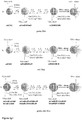
- the particle architecture is designed such that the dyes are added to a dye doped particle core in a layer-by-layer fashion and each spectrally distinct dye is spatially separated by a pure silica shell in order to reduce energy transfer between the dyes ( Figure 1 ). This assures maximum brightness levels and thus maximum signal-to-noise ratios in imaging.
- Optically encoded fluorescent silica nanoparticles having distinct fluorescent signatures were made, which can be used in the development for screening assays.
- the versatility of silica surface chemistry allowed the nanoparticle surface to be modified with biomolecular probes such as oligonucleotides or peptides.
- mc C dots In order to carry out the synthesis of mc C dots three issues were addressed: (1) identification of the appropriate fluorescent dyes, 'm', based on commonly available excitation laser line sources; (2) identification of the appropriate numbers of dyes that can be reproducibly incorporated into the particles in order to generate distinguishable fluorescence intensity levels, 'N', and (3) spatial separation of the spectrally distinct dyes within the particle to minimize energy transfer and hence fluorescence quenching in order to achieve maximum brightness levels.
- the three dyes chosen for developing mc C dots were DACm, TMRm and Cy5m, vide supra. The fluorescence intensity measured for a single particle and single color depends on the number of dyes incorporated in it.
- Figure 2b-i shows a schematic of the various layer-by-layer particle synthesis routes leading to the 26 distinct mc C dots.
- the notation used in this example to distinguish mc C dot color codes contains lower case letters to denote fluorescence intensity levels (m/h for medium/high, i.e. ⁇ 5/20 dyes per particle) and capital letters to denote fluorescence colors (G/R/B for green/red/blue emission, respectively).
- Each sequence moves from the core to the outer shell.
- a mGhRmB mc C dot has a medium green ( ⁇ 5 dyes) core, followed by a high red ( ⁇ 20 dyes) inner shell, followed by a medium blue ( ⁇ 5 dyes) outer shell.
- a color not present i.e.
- a hGhB mc C dot has a high green ( ⁇ 20 dyes) core, no red (i.e. zero red dyes), and a high blue ( ⁇ 20 dyes) outer shell.
- Particle synthesis was carried out by first conjugating commercially available maleimide activated dye (TMRm, Cy5m, or DACm) to 3-mercaptopropyl-trimethoxysilane (MPTMS) using the maleimide-mercapto bioconjugation reaction to form dye conjugate ( Figure 2b ).
- Three single color particles containing medium dye loadings (mG, mR, or mB, respectively, see Figure 2c-e ) were first synthesized via a modified Stöber-type silica condensation, by co-condensing the dye conjugate with TEOS at appropriate ammonia and water concentrations in alcohol. To this a thin silica shell was added by dosing the reaction solution with TEOS at concentrations below the nucleation threshold to avoid any secondary nucleation. A specific volume was removed from each reaction solution and these particles were set aside as particles with medium dye loadings.
- Such non-radiative energy transfer is the result of spectral overlap between the emission of a donor dye with the absorption spectrum of an acceptor dye.
- the efficiency of energy transfer between two dyes is determined by the Förster radius which is the distance at which 50% efficient energy transfer occurs between the donor and the acceptor.
- the calculated Förster radius for the pair DACm-TMRm is ⁇ 40 ⁇ (4.0 nm), while that of the pair TMRm-Cy5m is ⁇ 45 ⁇ (4.5 nm). Since DACm and Cy5m are on the extreme ends of the visible spectrum, with 15 ⁇ (1.5 nm) the Förster radius of this pair is the smallest.
- TMRm was the dye chosen to be in the center, to maintain consistency in the synthesis of different mc C dots, a large batch of medium and high dye loaded TMRm particles were synthesized.
- the next step to obtain dual-color C dots was to grow a 10-12 nm thick silica separation shell on these nanoparticles followed by the addition of Cy5m dye conjugate ( Figure 2f ). After adding a final silica shell, this accounted for particles with medium Cy5m (mR) dye loadings. Following this step, two additional Cy5m dye layers plus their silica shells were added to obtain high Cy5m (hR) dye loaded particles.
- Dual-color C dots with zero TMRm dyes per particle were synthesized using Cy5m core-shell particles as the template ( Figure 2h ).
- a large batch of medium Cy5m doped particles was synthesized which was split into two portions, leaving one batch as particles with medium Cy5m (mR) dye loading, while to the other batch three alternating Cy5m dye and silica shell layers were added to obtain high Cy5m (hR) dye loaded particles ( Figure 2d ).
- a silica separation shell of 6-8 nm thickness was grown on these mR/hR nanoparticles followed by the addition of DACm dye conjugate ( Figure 2h ). Together with a final silica shell this accounted for particles with medium DACm (mB) dye loadings.
- triple color C dots with high dye loadings for TMRm, Cy5m and DACm contain four TMRm dye and four silica shell layers added to the medium TMRm dye loaded core-shell particle (adding up to nine layers around the TMRm core), followed by three dye and three silica shell layers to obtain the high Cy5m dye loading, followed by four dye and four silica shell layers to obtain the high DACm dye loading. All particles were finally surface coated with a polyethylene glycol (PEG) layer to provide steric stabilization in buffer solutions and to render them more biocompatible.
- PEG polyethylene glycol
- FIG. 1a displays color renderings of these 26 particles assembled in a way reflecting the synthesis pathways described above.
- Figure 1b depicts a photo of the 26 particles in aqueous solutions in cuvettes under ambient light. Cuvettes are organized according to green TMRm dye loadings, with particles containing no, medium, and high TMRm dye loadings sitting in the bottom, middle, and upper rows, respectively (see Figure 4b for specific assignments). For comparison, the 27 th cuvette on the bottom left of Figure 1b is filled with non-dyed PEGylated silica nanoparticles.
- the dyes used for the nanoparticle syntheses were Cy5-maleimide (Cy5m, GE Healthcare Life Sciences), tetramethylrhodamine-5-maleimide (TMRm, Life Technologies) and N-(7-dimethylamino-4-methylcoumarin-3-yl)maleimide (DACm, Anaspec, Inc.).
- the dyes were dissolved in dimethyl sulfoxide (DMSO, anhydrous ⁇ 99.9%, Sigma Aldrich).
- DMSO dimethyl sulfoxide
- Ethoxy-silane terminated poly-(ethylene glycol) mPEG-Silane, molar mass ⁇ 5000 g/mol was purchased from Layson Bio.
- the reactions were carried out in ethanol (200 proof, Pharmaco-Aaper) and deionized water (DI water, 18.2 M ⁇ .cm -1 , purity, Millipore Milli-Q system).
- the particles were dialyzed using 10,000 molecular weight cut off (MWCO) Snakeskin dialysis membrane tube (Pierce) and were filtered with 0.2 ⁇ m PTFE syringe filters (Fisher Scientific).
- MWCO molecular weight cut off
- the particles were transferred into Dulbecco's Phosphate-Buffered Saline 1X buffer (DPBS without calcium and magnesium, Life Sciences) to carry out cell measurements using Macrosep® Advance Centrifugal Device, with a MWCO 30,000 (Pall Corporation).
- Nanoparticle Syntheses The maleimide derivative of the dyes TMRm (2.6 mM in DMSO), Cy5m (1.26 mM in DMSO) and DACm (3.4 mM in DMSO) were dissolved in DMSO in nitrogen atmosphere glove box for 15 hours.
- the dyes were conjugated with MPTMS in 1:25 dye to silane molar ratio in the glove box for 10-12 hours. Concentrations of 10 ⁇ 10 -5 M/4.0 ⁇ 10 -5 M/45 ⁇ 10 -5 M were used for TMRm/Cy5m/DACm dye conjugates, respectively.
- TMRm loaded particles 2 ⁇ 10 -5 M TMRm dye conjugate was added to 5 ml of mG reaction solution and left to stir for 8 hours, followed by addition of 0.105 M neat TEOS at a rate of 1 ⁇ l per ml of reaction volume every 30 minutes. The solution was left to stir for 4 hours before further TMRm dye layer-TEOS silica shell addition. This sequence was repeated a total of four times to obtain hG particles.
- Cy5m loaded particles 1 ⁇ 10 -5 M Cy5m dye conjugate was added to 5 ml of mR reaction solution and left to stir for 8 hours, followed by addition of 0.105 M neat TEOS at a rate of 1 ⁇ l per ml of reaction volume every 30 minutes. The solution was left to stir for 4 hours before further Cy5m dye layer-TEOS silica shell addition. This sequence was repeated a total of three times to obtain hR particles.
- DACm loaded particles To 5 ml of mB particle solutions, 5 ml of ethanol was added to synthesize high DACm loaded particles (hB). The concentrations of DI water and ammonia in ethanol were maintained at 0.88 M and 0.2 M, respectively. 9 ⁇ 10 -5 M DACm dye conjugate was added to the 10 ml reaction solution and left to stir for 8 hours, followed by 0.15 M neat TEOS at a rate of 1 ⁇ l per ml of reaction volume every 30 minutes. The solution was left to stir for 4 hours before further DACm dye layer-TEOS silica shell addition. This sequence was repeated a total of four times to obtain hB particle solutions.
- TMRm dye conjugate was added and left to stir for 8 hours, followed by addition of 0.105 M neat TEOS at a rate of 1 ⁇ l per ml of reaction volume every 30 minutes. The solution was left to stir for 4 hours before further TMRm dye layer-TEOS silica shell addition. This sequence was repeated a total of four times to obtain high TMRm particles (hG).
- DACm dye conjugate addition to dual color particles loaded with TMRm and Cy5m.
- 5 ⁇ 10 -5 M DACm dye conjugate was added to each of the reaction flasks containing 10 ml of mGmR, mGhR, hGmR and hGhR particle solutions and was left to stir for 8 hours.
- a thin silica shell was added to the reaction by drop wise addition of 0.15 M neat TEOS at a rate of 1 ⁇ l per milliliter of reaction volume every 30 minutes to form silica shell.
- 5 ml of the reaction solutions were set aside as mGmRmB, mGhRmB, hGmRmB and hGhRmB particles.
- silica shell growth on nanoparticles prior to PEGylation was grown on all particles by drop wise addition of TEOS to get the same size for all the nanoparticles.
- concentrations of DI water and ammonia in ethanol were maintained at 0.88 M and 0.2 M, respectively.
- PEGylation of mc C dots nanoparticles To 1.0 liter of DI water was adjusted to pH 5 by adding 2.0 M hydrochloric acid (aq.) using a pH meter (VWR International Symphony, SB70P). To carry out PEGylation, all the particles were grown to the same size as mentioned in the particle synthesis section. 0.08 M aqueous PEG-silane (mPEG-silane, M.W. 5k) solution was made by dissolving the PEG-silane in DI water at pH 5. 1 ml of this solution was taken in a vial and 2 ml of ethanol was added and the solution was left to stir for about 10 minutes. 1.0 ml of the as-made particle solution was added drop wise to 3 ml of mPEG-silane dissolved in the ethanol-water mixture, and then the solution was left to stir in an oil bath maintained at 70°C for 24 hours.
- mPEG-silane, M.W. 5k aqueous PEG-s
- the particles were dialyzed in DI water using 10,000 MWCO dialysis membrane tube and filtered with 0.2 ⁇ m PTFE syringe filters and stored in dark at room temperature for further characterization.
- the particles were transferred into a Dulbecco's Phosphate-Buffered Saline ( DPBS ) using Macrosep® Advance Centrifugal Device, with a MWCO of 30,000. Following dialysis, 5 ml of the PEGylated nanoparticle solution was added to 5 ml of buffer solution and centrifuged for 30 minutes at 3500 rpm. This process was repeated three times with buffer solution. As a final step the particles were heated to 75°C for 15 minutes to pasteurize the solution followed by the addition of 0.1 % (w/v) sodium azide aqueous solution.
- DPBS Dulbecco's Phosphate-Buffered Saline
- the particles were absorbance matched to the respective free dye by diluting the particles or free dye with DI water in a quartz cuvette using a Varian Cary 5000 Spectrometer (Varian, Palo Alto, CA).
- the extinction coefficients of DACm (25,000 M -1 cm -1 ), TMRm (98,000 M -1 cm -1 ) and Cy5m (250,000 M -1 cm -1 ) were used to quantify the concentration of dyes in the samples. Fluorescence measurements of absorbance matched samples were performed on a Photon Technologies International Quantamaster Spectrofluorometer (PTI, Birmingham, NJ).
- FCS Fluorescence Correlation Spectroscopy
- the emitted light from the sample was collected by the objective, passed through the excitation/emission dichroic and was reflected into a focusing lens by the emission mirror.
- the emission light was focused though a long pass filter (Chroma) to remove any excitation light and collect only the emission photons.
- Chroma long pass filter
- a 50 micron pinhole was used to axially limit the effective volume from which fluorescence was collected.
- the light then passed through a second lens into an avalanche photodiode (SPCM 14, Perkin Elmer).
- SPCM 14, Perkin Elmer avalanche photodiode
- the resulting photocurrent was digitally autocorrelated with a correlator card (Correlator.com).
- the data was fit using a triplet corrected autocorrelation function, as shown in the analytical form in equation 1.
- G ⁇ 1 + 1 N ⁇ 1 ⁇ A + A ⁇ exp t ⁇ R ⁇ 1 1 + t ⁇ D ⁇ 1 1 + t ⁇ D s 2
- A is the amplitude of triplet correction
- ⁇ R is the apparent diffusion time of a dye molecule/particle in the triplet state
- ⁇ D is the diffusion time of the molecule/particle in the singlet state
- N is the number of molecules in the focal volume.
- the structure factor parameter ' s ' describes the 3-D Gaussian focal volume in terms of the ratio of the axial to the radial axis and is calculated from measurements of the standard dye with known diffusion coefficient.
- the dyes used were N-(7-dimethylamino-4-methylcoumarin-3-yl)-maleimide, tetramethylrhodamine-5-maleimide and Alexa Fluor 647-maleimide, respectively.
- RBL-2H3 cells were maintained in monolayer culture in MEM supplemented with 20% FBS (Atlanta Biologicals) and 10 ⁇ g/ml gentamicin sulfate as previously described.
- Nanoparticle delivery into cells via electroporation Cells were harvested 3-5 days after passage and 1 ⁇ 10 6 /ml RBL-2H3 cells were electroporated in 0.5 ml of cold electroporation buffer (137 mM NaCl, 2.7 mM KCl, 1 mM MgCl 2 , 1 mg/ml glucose, 20 mM HEPES (pH 7.4) with 200 ⁇ l of nanoparticles suspended in DPBS buffer (5-10 ⁇ M).
- Square wave electroporation was used with settings of 280 V, 10.0 ms pulse length, 4 pulses, and pulse intervals of 0.1 ms using Gene Pulser X (Bio-Rad). This procedure was repeated for each of the 26 nanoparticles.
- Electroporated cells were allowed to recover for approximately an hour before being fixed with 4% paraformaldehyde and 0.1% glutaraldehyde. Fixed cells were then labeled with 0.5 ⁇ g/ml Alexa 488 cholera toxin subunit B for 15 min at room temperature to stain the cell membrane.
- FCS fluorescence correlation spectroscopy
- FCS is a diffusion based spectroscopy technique using the fluorescence of the diffusing moiety to generate an autocorrelation curve. Similar to dynamic light scattering (DLS), the time scale on which the correlation decays can be related to a diffusion coefficient which in turn can be related to a hydrodynamic radius/diameter of the diffusing moiety.
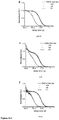
- Figure 3d-f compares the autocorrelation curves of the three parent dyes (solid lines) with those of the six single color C dots (mG, mR, and mB, open symbols; hG, hR, and hB, closed symbols) derived from the three dyes/colors at medium and high dye loadings, respectively.
- Dye incorporated nanoparticles diffuse much slower than the parent free dyes, confirming a significant increase in hydrodynamic radius from free dye to particle.
- medium and high dye level containing particles show very similar correlation curves revealing the high control over the final targeted particle size.
- a brightness factor for each dye-particle system can be calculated. This factor describes how much brighter the particles are relative to a single free dye in aqueous solution.
- the respective brightness factors determined in this way were: 9.1/35 for the medium/high TMRm particles, 9/33 for the medium/high Cy5m particles, and 36/144 for the medium/high DACm particles.
- the calculated brightness factors can be compared to the experimental brightness of the dyes and particles as measured by the count rates of the individual diffusing species on the optical FCS detector. This provides a direct measure of the brightness of the free dyes and particles, respectively.
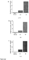
- Figure 3g-i show the results of these measurements.
- Figure 3g shows that medium/high TMRm loaded particles are 6.6 ( ⁇ 0.1)/32 ( ⁇ 0.4) times brighter than parent TMRm free dye, while for the Cy5m system,
- Figure 3h shows that medium/high Cy5m loaded particles are 5.3 ( ⁇ 0.2)/27.6 ( ⁇ 0.4) times brighter than the parent Cy5m free dye.
- Figure 3i compares the brightness for the DACm particle system and shows medium/high DACm loaded particles to be 24 ( ⁇ 3.0)/105 ( ⁇ 10) times brighter than parent DACm free dye, respectively.
- These direct brightness measurements confirm that as targeted, individual brightness levels are apart from one another by a factor of 4-6.
- the calculated brightness factors systematically overestimate the values obtained from FCS measurements. This may be due to an error in the determination of dye equivalents, which e.g. assumed no change in absorption cross section between free and encapsulated dyes. It may further be due to the fact that FCS measurements were carried out with polarized light, which possibly only excited sub-sets of the dyes in the particles, in turn leading to smaller counts per particle than expected from the brightness factor.
- Figure 4a shows representative FCS curves of specific particles moving towards triple color mc C dots covering the entire synthetic scheme starting from medium/high TMRm dye loaded single color C dots (mG, hollow circles/hG, full circles) via medium/high Cy5m dye loaded dual-color C dots (hGmR, hollow circles/hGhR, full circles) to the final triple color mc C dots with medium/high DACm dye loadings (hGhRmB, hollow circles/hGhRhB, full circles). All particles in this plot were terminated using a PEGylation step, although they were not grown to the same size of ⁇ 85 nm.
- Medium TMRm loaded core shell particle synthesis (mG, hollow green circles), resulted in particles of 15 nm ( ⁇ 0.5) diameter (including the PEG layer).
- Each of the four alternating dye and silica shell layers contributed 1.2-1.5 nm to the shell thickness (or 2.4-3 nm to the particle diameter).
- Dual-color particles with medium Cy5m dye loading first had a 10-12 nm thick silica shell (increasing the particle diameter by 20-24 nm) grafted onto the 28 nm diameter hG particles followed by the addition of one alternating Cy5m dye and silica shell layer (hGmR, hollow red circles).
- hGmR hollow red circles.
- particles containing the third, DACm dye had a 6-8 nm thick silica separator shell (increasing the particle diameter by 12-16 nm) grown onto the 57 nm ( ⁇ 2.2) hGhR particles followed by the addition of a single alternating DACm dye and silica shell layer, producing triple color C dots (hGhRmB, hollow blue circles) with a particle diameter of ⁇ 72 nm ( ⁇ 4.1). The increase in the particle size is noticeable when comparing the FCS curves of hGhR and hGhRmB.
- the final FCS curve in Figure 4a is from triple color C dots with high loadings of all three dyes (hGhRhB, solid blue circles) with three additional alternating DACm dye and silica shell layers plus a PEG surface layer, added to the hGhRmB particles resulting in a final particle diameter of 85 nm ( ⁇ 4.6).
- Figure 4b compares emission profiles from excitations at 405 nm, 540 nm, and 633 nm, respectively, of medium and high DACm (mB/hB), TMRm (mG/hG), and Cy5m (mR/hR) containing triple color particles.
- Particles with high DACm dye loading (hGhRhB) were ⁇ 3.8 times brighter than with medium DACm loading (hGhRmB) when excited at 405 nm.
- Particles with high TMRm dye loading (hGhRhB) were ⁇ 3.5 times brighter than with medium TMRm loading (mGhRhB) when excited at 540 nm.
- Figure 4c summarizes the spectroscopic brightness levels of all colors in all 26 particles in the form of bar graphs positioned in the identical way to the cuvettes in Figure 1b filled with particle solutions. Brightness levels were measured as the respective fluorescence emission maxima for each color of each particle as exemplified in Figure 4b . The height of the bars for each color was normalized to the brightness of particles with medium dye loading.
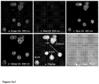
- Figure 5 shows confocal fluorescence microscopy images of mixture of cells, containing hB, hGhB, hGhR and hGhRmB particles, respectively.
- Figure 5 (a-d) show cell images as obtained in green, red, blue and yellow channels, upon exciting the cells at 560 nm, 633 nm, 405 nm and 488 nm, respectively. These images show emission for each color channel corresponding to photons emitted from each dye color present in the nanoparticle.
- RBL-2H3 cells show autofluorescence in the green ( Figure 5a ) and blue ( Figure 5b ) channel, however since the particles are bright, the high signal to noise ratio makes it possible to identify nanoparticles internalized in cells.
- Figure 5e shows the overlaid image of the four channels, where cells labeled with hB particles (blue circles) show emission only in the blue channel, with no emission in green or red channel, whereas cells labeled with hGhRmB (magenta circle) show emission in red, green and blue channels. Cells containing dual color particles, hGhB (yellow circle) and hGhR (red circle) show no contribution in the red and blue channels, respectively.
- Figure 5f shows the bright-field image of the cells showing that the morphology of these RBL-2H3 cells were intact after electroporation, thus making it possible to carry out cell imaging. Based on this figure we show that the mc C dots are internalized and from colocalizing the emission contribution from each channel, the nanoparticle stained cells can be distinguished from each other.
- This example is the first demonstration of intra -cellular fluorescence multiplexing utilizing multicolor silica nanoparticles.
- the bright mc C dots provide a platform to differentiate targets based on a simple RGB color code. It is expected that appropriate nanoparticle surface functionalization of these layer-by-layer particle architectures can provide as a powerful tool towards in vitro and in vivo applications in fundamental biology, cell signaling, biomedicine and high throughput cellular and pharmaceutical screening.
- each of 26 Rat Basophilic Leukemia (RBL) cell samples were mechanically transfected with a single type of particle via square-wave electroporation.
- Cells were membrane-labeled using an Alexa Fluor® 488 and cholera toxin conjugate. This fourth spectrally distinct fluorescent dye was chosen so that the fluorescent cell membrane could be distinguished from the mc C Dots inside the cells.
- Single-particle samples were plated directly on glass microscope slides and fixed before imaging. Mixing single-particle cell samples before plating enabled us to create multi-particle samples having only a single type of mc C Dot per cell.
- FIG. 6 A representative tile from a mixed-particle image, showing Alexa Fluor® 488 labeled RBL cells containing up to 17 different particles is shown in Figure 6 .
- the fluorescent images were also stacked in order to show that the cells have taken up a sufficiently high concentration of particles.
- Single cells were identified using the fluorescent cell-membrane label. Background fluorescence and cell aggregates were excluded using size analysis, whereby cells were approximated as circular areas of high intensity. Fluorescent entities with diameter below 5 ⁇ m or above 15 ⁇ m were considered to be outside the normal size range of single cells and thus were not analyzed. Single cell boundaries identified in this image were also applied to the corresponding RGB channel images. Only pixel intensities at positions on the cell interior were used in the remainder of this analysis. All image-processing algorithms were home-built and implemented using MATLAB.
- Single-particle images (1280 x 1280 pixel) were used to characterize the fluorescent signature of the corresponding mc C Dot. Individual cells were assigned mean red, green, and blue intensities, calculated using the brightest 50% of pixels in each cell. Low intensity pixels were excluded from this analysis in order to minimize the contribution from pixels containing few or no particles. Statistical analysis of red, green, and blue mean pixel intensities from more than 1000 cells were used to generate RGB thresholds that enable us to "decode" multi-particle images. Multi-particle images were analyzed cell-by-cell according to the results generated above. We have successfully "decoded" a 17-particle image according to this method as proof of concept. A false-colored version of this image (1280 x 1280 pixels) is shown in Figure 7 . In the figure, cells have been color-coded according to the "color" of the nanoparticle inside.
Landscapes
- Health & Medical Sciences (AREA)
- Life Sciences & Earth Sciences (AREA)
- Engineering & Computer Science (AREA)
- Chemical & Material Sciences (AREA)
- Immunology (AREA)
- Biomedical Technology (AREA)
- Urology & Nephrology (AREA)
- Molecular Biology (AREA)
- Hematology (AREA)
- Medicinal Chemistry (AREA)
- Pathology (AREA)
- Cell Biology (AREA)
- Biotechnology (AREA)
- Food Science & Technology (AREA)
- Microbiology (AREA)
- Physics & Mathematics (AREA)
- Analytical Chemistry (AREA)
- Biochemistry (AREA)
- General Health & Medical Sciences (AREA)
- General Physics & Mathematics (AREA)
- Nanotechnology (AREA)
- Organic Chemistry (AREA)
- Inorganic Chemistry (AREA)
- Investigating, Analyzing Materials By Fluorescence Or Luminescence (AREA)
- Silicon Compounds (AREA)
- Materials Engineering (AREA)
- Apparatus Associated With Microorganisms And Enzymes (AREA)
- Measuring Or Testing Involving Enzymes Or Micro-Organisms (AREA)
- Medicines Containing Antibodies Or Antigens For Use As Internal Diagnostic Agents (AREA)
Claims (17)
- Nanoparticule comprenant :a) un noyau de silice comprenant une pluralité d'un matériau réagissant par fluorescence (MRF) lié de façon covalente au réseau de silice du noyau ;b) de 1 à 100 couches de silice contenant un MRF, chaque couche comprenant une pluralité du MRF lié de façon covalente au réseau de silice de la couche de silice contenant un MRF ;c) une ou plusieurs couches de silice exemptes de MRF, l'une des couches de silice exemptes de MRF séparant le noyau de silice de l'une des couches de silice contenant un MRF et, le cas échéant, chaque paire adjacente des couches de silice contenant un MRF étant séparée par l'une des couches de silice exemptes de MRF ;d) une couche de silice exempte de MRF située tout à l'extérieur, disposée sur la couche de silice contenant un MRF située tout à l'extérieur ; ete) une pluralité de molécules de poly(éthylène glycol) liées de façon covalente à la surface extérieure de la couche de silice exempte de MRF située tout à l'extérieur ;dans laquelle chaque couche de silice exempte de MRF a une épaisseur de 1 nm à 20 nm.
- Nanoparticule selon la revendication 1, comprenant en outre une ou plusieurs fractions liées de façon covalente aux molécules de poly(éthylène glycol) liées de façon covalente à la surface extérieure de la couche de silice exempte de MRF située tout à l'extérieur.
- Nanoparticule selon la revendication 2, dans laquelle lesdites une ou plusieurs fractions sont sélectionnées parmi des protéines, des peptides, des acides nucléiques, des aptamères, des anticorps, des fragments d'anticorps, des polymères, des petites molécules organiques, et des combinaisons de ceux-ci.
- Nanoparticule selon la revendication 3, dans laquelle les acides nucléiques sont sélectionnés parmi des molécules d'ADN monobrin, des molécules d'ADN à double brin, des molécules d'ARN monobrin, des molécules d'ARN à double brin, des molécules d'ADN ramifiées, et des combinaisons de celles-ci.
- Nanoparticule selon la revendication 1, la nanoparticule ayant un diamètre de 5 nm à 500 nm.
- Nanoparticule selon la revendication 1, la nanoparticule ayant un diamètre de 5 nm à 100 nm.
- Nanoparticule selon la revendication 1, dans laquelle chaque couche de silice exempte de MRF a une épaisseur telle qu'un transfert d'énergie mesurable de 10 % ou moins a lieu entre le MRF dans le noyau et dans une couche de silice adjacente contenant un MRF ou dans des couches de silice adjacentes contenant un MRF.
- Nanoparticule selon la revendication 1, dans laquelle le noyau et toutes les couches contenant un MRF ont un différent MRF.
- Nanoparticule selon la revendication 1, dans laquelle le MRF est un colorant organique.
- Nanoparticule selon la revendication 1, dans laquelle le MRF est sélectionné parmi le N-(7-diméthylamino-4-méthylcoumarine-3-yle) (DAC), le tétraméthylrhodamine-5-maléimide (TMR), le Cy5, ou une combinaison de ceux-ci.
- Procédé de fabrication de la nanoparticule selon la revendication 1, comprenant les étapes qui consistent à :a) mettre en contact un précurseur de silice, une pluralité d'un seul type de précurseur de conjugué de MRF, un solvant, et une base, de façon à former un noyau de silice comportant une pluralité de MRF conjugué au réseau de silice du noyau de silice,b) mettre en contact le matériau issu de l'étape a) avec un précurseur de silice et un solvant de façon à former une couche de silice exempte de MRF sur le noyau de silice ;c) mettre en contact le matériau issu de l'étape b) avec un précurseur de silice, un seul type de précurseur de conjugué de MRF, un solvant, et une base, de façon à former une couche de silice contenant un MRF ;d) optionnellement, mettre en contact le matériau issu de l'étape c) avec un précurseur de silice et un solvant de façon à former une couche de silice exempte de MRF sur le noyau de silice, et mettre en contact le matériau obtenu avec un précurseur de silice, un seul type de précurseur de conjugué de MRF, un solvant, et une base, de façon à former une couche de silice contenant un MRF ;e) optionnellement, répéter l'étape d) autant de fois qu'on le souhaite, la mise en contact ayant lieu avec le matériau issu d'une étape d) exécutée précédemment ;f) mettre en contact le matériau issu de l'étape c), d), ou e) avec un précurseur de silice et un solvant de façon à former une couche de silice exempte de MRF située tout à l'extérieur sur la couche contenant un MRF située tout à l'extérieur ; etg) mettre en contact le matériau issu de l'étape f) avec des molécules de PEG fonctionnalisé de façon à former une nanoparticule comportant une pluralité de molécules de PEG liées de façon covalente à la surface extérieure de la couche de silice exempte de MRF située tout à l'extérieur de la nanoparticule.
- Procédé selon la revendication 11, dans lequel les molécules de PEG sont des molécules de PEG hétérobifonctionnel.
- Procédé selon la revendication 11, comprenant en outre l'étape d'isolation de la nanoparticule.
- Procédé d'imagerie comprenant les étapes qui consistent à :a) mettre en contact une cellule avec une pluralité de nanoparticules selon la revendication 1 ; etb) obtenir une pluralité d'images de l'échantillon, chaque image étant obtenue en utilisant une différente longueur d'onde d'excitation et une différente longueur d'onde d'émission, chaque différente longueur d'onde d'excitation se trouvant dans le spectre d'absorption d'un différent type de MRF présent dans la nanoparticule, et chaque différente longueur d'onde d'émission se trouvant dans le spectre d'émission d'un différent type de MRF présent dans la nanoparticule.
- Procédé d'imagerie selon la revendication 14, comprenant en outre l'étape de combinaison de la pluralité d'images pour produire une seule image.
- Procédé d'imagerie selon la revendication 14, dans lequel l'image est obtenue par microscopie confocale.
- Procédé d'imagerie selon la revendication 14, dans lequel la cellule est présente dans un sujet.
Applications Claiming Priority (2)
| Application Number | Priority Date | Filing Date | Title |
|---|---|---|---|
| US201361767066P | 2013-02-20 | 2013-02-20 | |
| PCT/US2014/017342 WO2014130643A1 (fr) | 2013-02-20 | 2014-02-20 | Nanoparticules fluorescentes multicouches et leurs procédés de fabrication et d'utilisation |
Publications (3)
| Publication Number | Publication Date |
|---|---|
| EP2959299A1 EP2959299A1 (fr) | 2015-12-30 |
| EP2959299A4 EP2959299A4 (fr) | 2016-09-21 |
| EP2959299B1 true EP2959299B1 (fr) | 2019-01-02 |
Family
ID=51391793
Family Applications (1)
| Application Number | Title | Priority Date | Filing Date |
|---|---|---|---|
| EP14754877.0A Active EP2959299B1 (fr) | 2013-02-20 | 2014-02-20 | Nanoparticules fluorescentes multicouches et leurs procédés de fabrication et d'utilisation |
Country Status (7)
| Country | Link |
|---|---|
| US (1) | US20160018404A1 (fr) |
| EP (1) | EP2959299B1 (fr) |
| JP (1) | JP6568802B2 (fr) |
| KR (1) | KR102290202B1 (fr) |
| CN (1) | CN105122065B (fr) |
| ES (1) | ES2709886T3 (fr) |
| WO (1) | WO2014130643A1 (fr) |
Families Citing this family (38)
| Publication number | Priority date | Publication date | Assignee | Title |
|---|---|---|---|---|
| US12161734B2 (en) | 2009-07-02 | 2024-12-10 | Sloan-Kettering Institute For Cancer Research | Multimodal silica-based nanoparticles |
| CN104684398A (zh) | 2012-08-31 | 2015-06-03 | 索隆-基特林癌症研究协会 | 粒子、方法以及其用途 |
| EP2958481A4 (fr) | 2013-02-20 | 2017-03-08 | Sloan-Kettering Institute for Cancer Research | Appareil d'imagerie raman à large champ et procédés associés |
| CA2900363C (fr) | 2013-03-15 | 2023-10-10 | Sloan-Kettering Institute For Cancer Research | Nanoparticules multimodales a base de silice |
| US10912947B2 (en) | 2014-03-04 | 2021-02-09 | Memorial Sloan Kettering Cancer Center | Systems and methods for treatment of disease via application of mechanical force by controlled rotation of nanoparticles inside cells |
| WO2016018896A1 (fr) | 2014-07-28 | 2016-02-04 | Memorial Sloan Kettering Cancer Center | Nanoparticules de chalcogène métallique (métalloïde) en tant que liants universels d'isotopes médicaux |
| US11291737B2 (en) * | 2015-05-04 | 2022-04-05 | Cornell University | Ultrasmall nanoparticles and methods of making and using same |
| US10736972B2 (en) | 2015-05-29 | 2020-08-11 | Memorial Sloan Kettering Cancer Center | Methods of treatment using ultrasmall nanoparticles to induce cell death of nutrient-deprived cancer cells via ferroptosis |
| WO2017004301A1 (fr) | 2015-07-01 | 2017-01-05 | Memorial Sloan Kettering Cancer Center | Particules anisotropes, leurs procédés et leurs utilisations |
| CN105510574B (zh) * | 2015-11-25 | 2018-11-20 | 深圳出入境检验检疫局食品检验检疫技术中心 | 荧光纳米探针及其制备方法和用于食品中多种危害因子同步检测的方法 |
| WO2017189961A1 (fr) | 2016-04-29 | 2017-11-02 | Memorial Sloan Kettering Cancer Center | Compositions et procédés pour la pénétration, la distribution et la réponse ciblées de particules dans des tumeurs malignes du cerveau |
| WO2018037060A1 (fr) * | 2016-08-25 | 2018-03-01 | Roche Diagnostics Gmbh | Nanoparticules de silicium multifonctionnalisées, leurs procédés de préparation et leurs utilisations dans des procédés de détection fondés sur l'électrochimioluminescence |
| GB2554666B (en) * | 2016-09-30 | 2019-12-18 | Sumitomo Chemical Co | Composite Particle |
| WO2018191316A1 (fr) | 2017-04-10 | 2018-10-18 | Cornell University | Nanoparticules contenant du soufre ou un atome lourd, procédés pour les fabriquer, et leurs utilisations |
| JP7309198B2 (ja) * | 2017-05-19 | 2023-07-18 | コーネル ユニバーシティー | 機能性ナノ粒子及びそれを製造する方法並びに使用する方法 |
| WO2018217528A1 (fr) | 2017-05-25 | 2018-11-29 | Memorial Sloan Kettering Cancer Center | Nanoparticules ultra-petites marquées avec du zirconium-89 et leurs procédés |
| US20200383943A1 (en) | 2017-12-04 | 2020-12-10 | Memorial Sloan Kettering Cancer Center | Methods of cancer treatment via regulated ferroptosis |
| US20190249360A1 (en) | 2018-02-15 | 2019-08-15 | Buckman Laboratories International, Inc. | Method And System For Tagging Leather Or Hides Treated With Biocide And Identifying Same |
| WO2019213458A1 (fr) * | 2018-05-02 | 2019-11-07 | Cornell University | Nanophotosensibilisateurs inorganiques et leurs procédés de fabrication et d'utilisation |
| US12268742B2 (en) | 2018-05-02 | 2025-04-08 | Memorial Sloan Kettering Cancer Center | Nanotherapeutic systems and methods using particle-driven photodynamic therapy (PDT) |
| US11666411B2 (en) | 2018-05-10 | 2023-06-06 | Memorial Sloan Kettering Cancer Center | Systems for augmented reality surgical and clinical visualization |
| WO2020046027A1 (fr) * | 2018-08-30 | 2020-03-05 | 주식회사 엘지화학 | Dispositif comprenant des microbilles capables d'ajuster le ph d'un échantillon |
| KR101998073B1 (ko) | 2018-10-05 | 2019-07-09 | 이선언 | 이중 와류형 공기청정기 |
| US11354466B1 (en) | 2018-11-02 | 2022-06-07 | Inkbit, LLC | Machine learning for additive manufacturing |
| CA3118328A1 (fr) | 2018-11-02 | 2020-05-07 | Inkbit, LLC | Fabrication additive intelligente |
| US11667071B2 (en) | 2018-11-16 | 2023-06-06 | Inkbit, LLC | Inkjet 3D printing of multi-component resins |
| US10974460B2 (en) | 2019-01-08 | 2021-04-13 | Inkbit, LLC | Reconstruction of surfaces for additive manufacturing |
| EP3884237A1 (fr) | 2019-01-08 | 2021-09-29 | Inkbit, LLC | Reconstruction de profondeur dans la fabrication additive |
| CN110407986B (zh) * | 2019-07-30 | 2021-07-30 | 中北大学 | 一种pH、温度响应型双壳层空心微球的制备方法 |
| US10994477B1 (en) * | 2019-11-01 | 2021-05-04 | Inkbit, LLC | Optical scanning for industrial metrology |
| US11712837B2 (en) | 2019-11-01 | 2023-08-01 | Inkbit, LLC | Optical scanning for industrial metrology |
| JP7467974B2 (ja) * | 2020-02-17 | 2024-04-16 | 富士フイルムビジネスイノベーション株式会社 | 樹脂粒子 |
| GB2592615A (en) * | 2020-03-03 | 2021-09-08 | Sumitomo Chemical Co | Light-emitting particles |
| US10994490B1 (en) | 2020-07-31 | 2021-05-04 | Inkbit, LLC | Calibration for additive manufacturing by compensating for geometric misalignments and distortions between components of a 3D printer |
| WO2022093800A2 (fr) | 2020-10-27 | 2022-05-05 | Elucida Oncology, Inc. | Conjugués particule vecteur-médicament lieurs auto-immolateurs et leurs utilisations |
| US20250243371A1 (en) * | 2022-08-08 | 2025-07-31 | The University Of Chicago | Nanoparticle-containing media exhibiting enhanced optical transparency, related nanoparticles, and associated systems and methods |
| KR20250128235A (ko) * | 2024-02-20 | 2025-08-27 | 주식회사 심비스타 | Nmda 수용체 항체 및 형광물질을 포함하는 신규 테라그노스틱 나노복합체 및 이것의 용도 |
| CN118496714A (zh) * | 2024-06-06 | 2024-08-16 | 山西大学 | 一种新型多色碳纳米隐形防伪墨水的制备方法 |
Family Cites Families (7)
| Publication number | Priority date | Publication date | Assignee | Title |
|---|---|---|---|---|
| WO2003075765A1 (fr) * | 2002-03-05 | 2003-09-18 | Board Of Regents, The University Of Texas System | Produits de contraste biospecifiques |
| WO2008033804A2 (fr) * | 2006-09-11 | 2008-03-20 | The Arizona Board Of Regents, A Body Corporate Of The State Of Arizona Acting For And On Behalf Of Arizona State University | Structures de codes à barres à points quantiques et utilisations associées |
| CN101050358A (zh) * | 2007-04-30 | 2007-10-10 | 吉林大学 | 一种染料可控掺杂二氧化硅纳米粒子的制备方法 |
| WO2010111674A2 (fr) * | 2009-03-27 | 2010-09-30 | Life Technologies Corporation | Procédés et appareil de séquençage de molécules uniques utilisant la détection par transfert d'énergie |
| DK3223013T3 (en) * | 2009-07-02 | 2019-04-15 | Sloan Kettering Inst Cancer Res | FLUORESCING SILICA-BASED NANOPARTICLES |
| US10520500B2 (en) * | 2009-10-09 | 2019-12-31 | Abdeslam El Harrak | Labelled silica-based nanomaterial with enhanced properties and uses thereof |
| WO2011072228A1 (fr) * | 2009-12-11 | 2011-06-16 | Massachusetts Institute Of Technology | Imagerie spectrale de matériaux photoluminescents |
-
2014
- 2014-02-20 EP EP14754877.0A patent/EP2959299B1/fr active Active
- 2014-02-20 US US14/768,890 patent/US20160018404A1/en not_active Abandoned
- 2014-02-20 ES ES14754877T patent/ES2709886T3/es active Active
- 2014-02-20 JP JP2015558943A patent/JP6568802B2/ja active Active
- 2014-02-20 WO PCT/US2014/017342 patent/WO2014130643A1/fr not_active Ceased
- 2014-02-20 KR KR1020157026027A patent/KR102290202B1/ko active Active
- 2014-02-20 CN CN201480022519.8A patent/CN105122065B/zh active Active
Non-Patent Citations (1)
| Title |
|---|
| None * |
Also Published As
| Publication number | Publication date |
|---|---|
| WO2014130643A1 (fr) | 2014-08-28 |
| US20160018404A1 (en) | 2016-01-21 |
| CN105122065A (zh) | 2015-12-02 |
| CN105122065B (zh) | 2018-05-25 |
| KR102290202B1 (ko) | 2021-08-20 |
| KR20150121130A (ko) | 2015-10-28 |
| ES2709886T3 (es) | 2019-04-22 |
| JP6568802B2 (ja) | 2019-08-28 |
| EP2959299A4 (fr) | 2016-09-21 |
| EP2959299A1 (fr) | 2015-12-30 |
| JP2016520287A (ja) | 2016-07-14 |
Similar Documents
| Publication | Publication Date | Title |
|---|---|---|
| EP2959299B1 (fr) | Nanoparticules fluorescentes multicouches et leurs procédés de fabrication et d'utilisation | |
| Fan et al. | Optical multiplexed bioassays for improved biomedical diagnostics | |
| US20200217843A1 (en) | Labelled silica-based nanomaterial with enhanced properties and uses thereof | |
| Gust et al. | A starting point for fluorescence-based single-molecule measurements in biomolecular research | |
| Haustein et al. | Fluorescence correlation spectroscopy: novel variations of an established technique | |
| Yu et al. | Smartphone fluorescence spectroscopy | |
| CN115087747A (zh) | 使用时间分辨发光测量法对生物材料进行空间分析的组合物和方法 | |
| Borisov et al. | Optical nanosensors—smart tools in bioanalytics | |
| WO2011113345A1 (fr) | Système et procédés de détection de molécules individuelles | |
| JP2015111167A (ja) | 組織染色方法および生体物質検出方法 | |
| Schirripa Spagnolo et al. | Choosing the probe for single-molecule fluorescence microscopy | |
| Liu et al. | QD-Biopolymer-TSPP assembly as efficient BiFRET sensor for ratiometric and visual detection of zinc ion | |
| CN101443459A (zh) | 用于在分析检测方法中校正样品基体效应的样品对照 | |
| Cha et al. | High-throughput multiplex analysis method based on Fluorescence–SERS quantum Dot-Embedded silver bumpy nanoprobes | |
| Menendez-Miranda et al. | Determination of the ratio of fluorophore/nanoparticle for fluorescence-labelled nanoparticles | |
| EP2743684B1 (fr) | Procédé de détection de particules fluorescentes | |
| Pan et al. | Luminescence-sensitive surfaces bearing ratiometric nanoparticles for bacteria growth detection | |
| Singh Chauhan et al. | Spectroscopic and in silico studies of HPTS (Pyranine) with bilirubin for sol–gel based sensor applications | |
| Patonay et al. | Fluorescent silica nanoparticles containing covalently bound dyes for reporter, marker, and sensor applications | |
| Tsai | Development and characterization of photoluminescent materials towards applications of concentric Fӧrster resonance energy transfer probes in bioanalysis | |
| Biswas | Light-harvesting nanomaterials for single molecule detection and energy transport | |
| Blagoi | Fluorescence resonance energy transfer (FRET) based sensors for bioanalysis | |
| Morassuti et al. | Multienergy Calibration Applied for the Quantification of Polymer Concentration in Conjugated Polymer Nanoparticles | |
| Fayad | Versatile FREΤ-Based Fluοrescent Νanοprοbes fοr Biοsensing and Biοimaging Applicatiοns. | |
| CN121896342A (zh) | 一种基于InP量子点与miRNA触发DNA步行器的阿尔茨海默病生物标志物信号放大检测生物传感器及其制备方法和应用 |
Legal Events
| Date | Code | Title | Description |
|---|---|---|---|
| PUAI | Public reference made under article 153(3) epc to a published international application that has entered the european phase |
Free format text: ORIGINAL CODE: 0009012 |
|
| 17P | Request for examination filed |
Effective date: 20150921 |
|
| AK | Designated contracting states |
Kind code of ref document: A1 Designated state(s): AL AT BE BG CH CY CZ DE DK EE ES FI FR GB GR HR HU IE IS IT LI LT LU LV MC MK MT NL NO PL PT RO RS SE SI SK SM TR |
|
| AX | Request for extension of the european patent |
Extension state: BA ME |
|
| DAX | Request for extension of the european patent (deleted) | ||
| REG | Reference to a national code |
Ref country code: DE Ref legal event code: R079 Ref document number: 602014039147 Country of ref document: DE Free format text: PREVIOUS MAIN CLASS: G01N0033580000 Ipc: G01N0033543000 |
|
| A4 | Supplementary search report drawn up and despatched |
Effective date: 20160823 |
|
| RIC1 | Information provided on ipc code assigned before grant |
Ipc: B05D 5/06 20060101ALI20160817BHEP Ipc: G01N 33/552 20060101ALI20160817BHEP Ipc: B32B 19/00 20060101ALI20160817BHEP Ipc: G01N 33/58 20060101ALI20160817BHEP Ipc: G01N 33/543 20060101AFI20160817BHEP |
|
| STAA | Information on the status of an ep patent application or granted ep patent |
Free format text: STATUS: EXAMINATION IS IN PROGRESS |
|
| 17Q | First examination report despatched |
Effective date: 20170818 |
|
| GRAP | Despatch of communication of intention to grant a patent |
Free format text: ORIGINAL CODE: EPIDOSNIGR1 |
|
| STAA | Information on the status of an ep patent application or granted ep patent |
Free format text: STATUS: GRANT OF PATENT IS INTENDED |
|
| INTG | Intention to grant announced |
Effective date: 20180712 |
|
| RAP1 | Party data changed (applicant data changed or rights of an application transferred) |
Owner name: CORNELL UNIVERSITY |
|
| GRAS | Grant fee paid |
Free format text: ORIGINAL CODE: EPIDOSNIGR3 |
|
| GRAA | (expected) grant |
Free format text: ORIGINAL CODE: 0009210 |
|
| STAA | Information on the status of an ep patent application or granted ep patent |
Free format text: STATUS: THE PATENT HAS BEEN GRANTED |
|
| RAP1 | Party data changed (applicant data changed or rights of an application transferred) |
Owner name: CORNELL UNIVERSITY |
|
| AK | Designated contracting states |
Kind code of ref document: B1 Designated state(s): AL AT BE BG CH CY CZ DE DK EE ES FI FR GB GR HR HU IE IS IT LI LT LU LV MC MK MT NL NO PL PT RO RS SE SI SK SM TR |
|
| REG | Reference to a national code |
Ref country code: GB Ref legal event code: FG4D |
|
| REG | Reference to a national code |
Ref country code: CH Ref legal event code: EP Ref country code: AT Ref legal event code: REF Ref document number: 1085055 Country of ref document: AT Kind code of ref document: T Effective date: 20190115 |
|
| REG | Reference to a national code |
Ref country code: IE Ref legal event code: FG4D |
|
| REG | Reference to a national code |
Ref country code: DE Ref legal event code: R096 Ref document number: 602014039147 Country of ref document: DE |
|
| REG | Reference to a national code |
Ref country code: NL Ref legal event code: FP |
|
| REG | Reference to a national code |
Ref country code: NO Ref legal event code: T2 Effective date: 20190102 |
|
| REG | Reference to a national code |
Ref country code: SE Ref legal event code: TRGR |
|
| REG | Reference to a national code |
Ref country code: ES Ref legal event code: FG2A Ref document number: 2709886 Country of ref document: ES Kind code of ref document: T3 Effective date: 20190422 |
|
| REG | Reference to a national code |
Ref country code: LT Ref legal event code: MG4D |
|
| REG | Reference to a national code |
Ref country code: AT Ref legal event code: MK05 Ref document number: 1085055 Country of ref document: AT Kind code of ref document: T Effective date: 20190102 |
|
| PG25 | Lapsed in a contracting state [announced via postgrant information from national office to epo] |
Ref country code: PL Free format text: LAPSE BECAUSE OF FAILURE TO SUBMIT A TRANSLATION OF THE DESCRIPTION OR TO PAY THE FEE WITHIN THE PRESCRIBED TIME-LIMIT Effective date: 20190102 Ref country code: FI Free format text: LAPSE BECAUSE OF FAILURE TO SUBMIT A TRANSLATION OF THE DESCRIPTION OR TO PAY THE FEE WITHIN THE PRESCRIBED TIME-LIMIT Effective date: 20190102 Ref country code: LT Free format text: LAPSE BECAUSE OF FAILURE TO SUBMIT A TRANSLATION OF THE DESCRIPTION OR TO PAY THE FEE WITHIN THE PRESCRIBED TIME-LIMIT Effective date: 20190102 Ref country code: PT Free format text: LAPSE BECAUSE OF FAILURE TO SUBMIT A TRANSLATION OF THE DESCRIPTION OR TO PAY THE FEE WITHIN THE PRESCRIBED TIME-LIMIT Effective date: 20190502 |
|
| PG25 | Lapsed in a contracting state [announced via postgrant information from national office to epo] |
Ref country code: GR Free format text: LAPSE BECAUSE OF FAILURE TO SUBMIT A TRANSLATION OF THE DESCRIPTION OR TO PAY THE FEE WITHIN THE PRESCRIBED TIME-LIMIT Effective date: 20190403 Ref country code: RS Free format text: LAPSE BECAUSE OF FAILURE TO SUBMIT A TRANSLATION OF THE DESCRIPTION OR TO PAY THE FEE WITHIN THE PRESCRIBED TIME-LIMIT Effective date: 20190102 Ref country code: BG Free format text: LAPSE BECAUSE OF FAILURE TO SUBMIT A TRANSLATION OF THE DESCRIPTION OR TO PAY THE FEE WITHIN THE PRESCRIBED TIME-LIMIT Effective date: 20190402 Ref country code: IS Free format text: LAPSE BECAUSE OF FAILURE TO SUBMIT A TRANSLATION OF THE DESCRIPTION OR TO PAY THE FEE WITHIN THE PRESCRIBED TIME-LIMIT Effective date: 20190502 Ref country code: HR Free format text: LAPSE BECAUSE OF FAILURE TO SUBMIT A TRANSLATION OF THE DESCRIPTION OR TO PAY THE FEE WITHIN THE PRESCRIBED TIME-LIMIT Effective date: 20190102 Ref country code: LV Free format text: LAPSE BECAUSE OF FAILURE TO SUBMIT A TRANSLATION OF THE DESCRIPTION OR TO PAY THE FEE WITHIN THE PRESCRIBED TIME-LIMIT Effective date: 20190102 |
|
| REG | Reference to a national code |
Ref country code: CH Ref legal event code: PL |
|
| REG | Reference to a national code |
Ref country code: DE Ref legal event code: R097 Ref document number: 602014039147 Country of ref document: DE |
|
| PG25 | Lapsed in a contracting state [announced via postgrant information from national office to epo] |
Ref country code: AL Free format text: LAPSE BECAUSE OF FAILURE TO SUBMIT A TRANSLATION OF THE DESCRIPTION OR TO PAY THE FEE WITHIN THE PRESCRIBED TIME-LIMIT Effective date: 20190102 Ref country code: AT Free format text: LAPSE BECAUSE OF FAILURE TO SUBMIT A TRANSLATION OF THE DESCRIPTION OR TO PAY THE FEE WITHIN THE PRESCRIBED TIME-LIMIT Effective date: 20190102 Ref country code: MC Free format text: LAPSE BECAUSE OF FAILURE TO SUBMIT A TRANSLATION OF THE DESCRIPTION OR TO PAY THE FEE WITHIN THE PRESCRIBED TIME-LIMIT Effective date: 20190102 Ref country code: EE Free format text: LAPSE BECAUSE OF FAILURE TO SUBMIT A TRANSLATION OF THE DESCRIPTION OR TO PAY THE FEE WITHIN THE PRESCRIBED TIME-LIMIT Effective date: 20190102 Ref country code: DK Free format text: LAPSE BECAUSE OF FAILURE TO SUBMIT A TRANSLATION OF THE DESCRIPTION OR TO PAY THE FEE WITHIN THE PRESCRIBED TIME-LIMIT Effective date: 20190102 Ref country code: SK Free format text: LAPSE BECAUSE OF FAILURE TO SUBMIT A TRANSLATION OF THE DESCRIPTION OR TO PAY THE FEE WITHIN THE PRESCRIBED TIME-LIMIT Effective date: 20190102 Ref country code: LU Free format text: LAPSE BECAUSE OF NON-PAYMENT OF DUE FEES Effective date: 20190220 Ref country code: RO Free format text: LAPSE BECAUSE OF FAILURE TO SUBMIT A TRANSLATION OF THE DESCRIPTION OR TO PAY THE FEE WITHIN THE PRESCRIBED TIME-LIMIT Effective date: 20190102 Ref country code: CZ Free format text: LAPSE BECAUSE OF FAILURE TO SUBMIT A TRANSLATION OF THE DESCRIPTION OR TO PAY THE FEE WITHIN THE PRESCRIBED TIME-LIMIT Effective date: 20190102 |
|
| PLBE | No opposition filed within time limit |
Free format text: ORIGINAL CODE: 0009261 |
|
| STAA | Information on the status of an ep patent application or granted ep patent |
Free format text: STATUS: NO OPPOSITION FILED WITHIN TIME LIMIT |
|
| REG | Reference to a national code |
Ref country code: BE Ref legal event code: MM Effective date: 20190228 |
|
| REG | Reference to a national code |
Ref country code: IE Ref legal event code: MM4A |
|
| PG25 | Lapsed in a contracting state [announced via postgrant information from national office to epo] |
Ref country code: SM Free format text: LAPSE BECAUSE OF FAILURE TO SUBMIT A TRANSLATION OF THE DESCRIPTION OR TO PAY THE FEE WITHIN THE PRESCRIBED TIME-LIMIT Effective date: 20190102 |
|
| 26N | No opposition filed |
Effective date: 20191003 |
|
| PG25 | Lapsed in a contracting state [announced via postgrant information from national office to epo] |
Ref country code: CH Free format text: LAPSE BECAUSE OF NON-PAYMENT OF DUE FEES Effective date: 20190228 Ref country code: LI Free format text: LAPSE BECAUSE OF NON-PAYMENT OF DUE FEES Effective date: 20190228 |
|
| PG25 | Lapsed in a contracting state [announced via postgrant information from national office to epo] |
Ref country code: IE Free format text: LAPSE BECAUSE OF NON-PAYMENT OF DUE FEES Effective date: 20190220 |
|
| PG25 | Lapsed in a contracting state [announced via postgrant information from national office to epo] |
Ref country code: BE Free format text: LAPSE BECAUSE OF NON-PAYMENT OF DUE FEES Effective date: 20190228 Ref country code: SI Free format text: LAPSE BECAUSE OF FAILURE TO SUBMIT A TRANSLATION OF THE DESCRIPTION OR TO PAY THE FEE WITHIN THE PRESCRIBED TIME-LIMIT Effective date: 20190102 |
|
| PG25 | Lapsed in a contracting state [announced via postgrant information from national office to epo] |
Ref country code: TR Free format text: LAPSE BECAUSE OF FAILURE TO SUBMIT A TRANSLATION OF THE DESCRIPTION OR TO PAY THE FEE WITHIN THE PRESCRIBED TIME-LIMIT Effective date: 20190102 |
|
| PG25 | Lapsed in a contracting state [announced via postgrant information from national office to epo] |
Ref country code: MT Free format text: LAPSE BECAUSE OF NON-PAYMENT OF DUE FEES Effective date: 20190220 |
|
| PG25 | Lapsed in a contracting state [announced via postgrant information from national office to epo] |
Ref country code: CY Free format text: LAPSE BECAUSE OF FAILURE TO SUBMIT A TRANSLATION OF THE DESCRIPTION OR TO PAY THE FEE WITHIN THE PRESCRIBED TIME-LIMIT Effective date: 20190102 |
|
| PG25 | Lapsed in a contracting state [announced via postgrant information from national office to epo] |
Ref country code: HU Free format text: LAPSE BECAUSE OF FAILURE TO SUBMIT A TRANSLATION OF THE DESCRIPTION OR TO PAY THE FEE WITHIN THE PRESCRIBED TIME-LIMIT; INVALID AB INITIO Effective date: 20140220 |
|
| REG | Reference to a national code |
Ref country code: DE Ref legal event code: R082 Ref document number: 602014039147 Country of ref document: DE Representative=s name: ZACCO LEGAL RECHTSANWALTSGESELLSCHAFT MBH, DE |
|
| PG25 | Lapsed in a contracting state [announced via postgrant information from national office to epo] |
Ref country code: MK Free format text: LAPSE BECAUSE OF FAILURE TO SUBMIT A TRANSLATION OF THE DESCRIPTION OR TO PAY THE FEE WITHIN THE PRESCRIBED TIME-LIMIT Effective date: 20190102 |
|
| P01 | Opt-out of the competence of the unified patent court (upc) registered |
Effective date: 20230519 |
|
| PGFP | Annual fee paid to national office [announced via postgrant information from national office to epo] |
Ref country code: NL Payment date: 20250227 Year of fee payment: 12 |
|
| PGFP | Annual fee paid to national office [announced via postgrant information from national office to epo] |
Ref country code: DE Payment date: 20250227 Year of fee payment: 12 |
|
| PGFP | Annual fee paid to national office [announced via postgrant information from national office to epo] |
Ref country code: ES Payment date: 20250303 Year of fee payment: 12 |
|
| PGFP | Annual fee paid to national office [announced via postgrant information from national office to epo] |
Ref country code: SE Payment date: 20250227 Year of fee payment: 12 |
|
| PGFP | Annual fee paid to national office [announced via postgrant information from national office to epo] |
Ref country code: NO Payment date: 20250227 Year of fee payment: 12 |
|
| PGFP | Annual fee paid to national office [announced via postgrant information from national office to epo] |
Ref country code: FR Payment date: 20250225 Year of fee payment: 12 |
|
| PGFP | Annual fee paid to national office [announced via postgrant information from national office to epo] |
Ref country code: IT Payment date: 20250220 Year of fee payment: 12 Ref country code: GB Payment date: 20250227 Year of fee payment: 12 |
|
| REG | Reference to a national code |
Ref country code: DE Ref legal event code: R082 Ref document number: 602014039147 Country of ref document: DE |