EP2959573B1 - Procédé et système permettant de déterminer la position d'un rotor d'un moteur synchrone - Google Patents
Procédé et système permettant de déterminer la position d'un rotor d'un moteur synchrone Download PDFInfo
- Publication number
- EP2959573B1 EP2959573B1 EP14708421.4A EP14708421A EP2959573B1 EP 2959573 B1 EP2959573 B1 EP 2959573B1 EP 14708421 A EP14708421 A EP 14708421A EP 2959573 B1 EP2959573 B1 EP 2959573B1
- Authority
- EP
- European Patent Office
- Prior art keywords
- voltage
- phase
- measured
- stator windings
- motor
- Prior art date
- Legal status (The legal status is an assumption and is not a legal conclusion. Google has not performed a legal analysis and makes no representation as to the accuracy of the status listed.)
- Active
Links
Images



Classifications
-
- H—ELECTRICITY
- H02—GENERATION; CONVERSION OR DISTRIBUTION OF ELECTRIC POWER
- H02P—CONTROL OR REGULATION OF ELECTRIC MOTORS, ELECTRIC GENERATORS OR DYNAMO-ELECTRIC CONVERTERS; CONTROLLING TRANSFORMERS, REACTORS OR CHOKE COILS
- H02P6/00—Arrangements for controlling synchronous motors or other dynamo-electric motors using electronic commutation dependent on the rotor position; Electronic commutators therefor
- H02P6/14—Electronic commutators
- H02P6/16—Circuit arrangements for detecting position
- H02P6/18—Circuit arrangements for detecting position without separate position detecting elements
- H02P6/182—Circuit arrangements for detecting position without separate position detecting elements using back-emf in windings
-
- H—ELECTRICITY
- H02—GENERATION; CONVERSION OR DISTRIBUTION OF ELECTRIC POWER
- H02P—CONTROL OR REGULATION OF ELECTRIC MOTORS, ELECTRIC GENERATORS OR DYNAMO-ELECTRIC CONVERTERS; CONTROLLING TRANSFORMERS, REACTORS OR CHOKE COILS
- H02P6/00—Arrangements for controlling synchronous motors or other dynamo-electric motors using electronic commutation dependent on the rotor position; Electronic commutators therefor
- H02P6/14—Electronic commutators
- H02P6/16—Circuit arrangements for detecting position
- H02P6/18—Circuit arrangements for detecting position without separate position detecting elements
- H02P6/186—Circuit arrangements for detecting position without separate position detecting elements using difference of inductance or reluctance between the phases
-
- H—ELECTRICITY
- H02—GENERATION; CONVERSION OR DISTRIBUTION OF ELECTRIC POWER
- H02P—CONTROL OR REGULATION OF ELECTRIC MOTORS, ELECTRIC GENERATORS OR DYNAMO-ELECTRIC CONVERTERS; CONTROLLING TRANSFORMERS, REACTORS OR CHOKE COILS
- H02P6/00—Arrangements for controlling synchronous motors or other dynamo-electric motors using electronic commutation dependent on the rotor position; Electronic commutators therefor
- H02P6/14—Electronic commutators
- H02P6/16—Circuit arrangements for detecting position
- H02P6/18—Circuit arrangements for detecting position without separate position detecting elements
- H02P6/185—Circuit arrangements for detecting position without separate position detecting elements using inductance sensing, e.g. pulse excitation
-
- H—ELECTRICITY
- H02—GENERATION; CONVERSION OR DISTRIBUTION OF ELECTRIC POWER
- H02K—DYNAMO-ELECTRIC MACHINES
- H02K29/00—Motors or generators having non-mechanical commutating devices, e.g. discharge tubes or semiconductor devices
- H02K29/06—Motors or generators having non-mechanical commutating devices, e.g. discharge tubes or semiconductor devices with position sensing devices
- H02K29/12—Motors or generators having non-mechanical commutating devices, e.g. discharge tubes or semiconductor devices with position sensing devices using detecting coils using the machine windings as detecting coil
-
- H—ELECTRICITY
- H02—GENERATION; CONVERSION OR DISTRIBUTION OF ELECTRIC POWER
- H02P—CONTROL OR REGULATION OF ELECTRIC MOTORS, ELECTRIC GENERATORS OR DYNAMO-ELECTRIC CONVERTERS; CONTROLLING TRANSFORMERS, REACTORS OR CHOKE COILS
- H02P21/00—Arrangements or methods for the control of electric machines by vector control, e.g. by control of field orientation
- H02P21/0085—Arrangements or methods for the control of electric machines by vector control, e.g. by control of field orientation specially adapted for high speeds, e.g. above nominal speed
-
- H—ELECTRICITY
- H02—GENERATION; CONVERSION OR DISTRIBUTION OF ELECTRIC POWER
- H02P—CONTROL OR REGULATION OF ELECTRIC MOTORS, ELECTRIC GENERATORS OR DYNAMO-ELECTRIC CONVERTERS; CONTROLLING TRANSFORMERS, REACTORS OR CHOKE COILS
- H02P21/00—Arrangements or methods for the control of electric machines by vector control, e.g. by control of field orientation
- H02P21/14—Estimation or adaptation of machine parameters, e.g. flux, current or voltage
- H02P21/18—Estimation of position or speed
-
- H—ELECTRICITY
- H02—GENERATION; CONVERSION OR DISTRIBUTION OF ELECTRIC POWER
- H02P—CONTROL OR REGULATION OF ELECTRIC MOTORS, ELECTRIC GENERATORS OR DYNAMO-ELECTRIC CONVERTERS; CONTROLLING TRANSFORMERS, REACTORS OR CHOKE COILS
- H02P21/00—Arrangements or methods for the control of electric machines by vector control, e.g. by control of field orientation
- H02P21/24—Vector control not involving the use of rotor position or rotor speed sensors
- H02P21/32—Determining the initial rotor position
-
- H—ELECTRICITY
- H02—GENERATION; CONVERSION OR DISTRIBUTION OF ELECTRIC POWER
- H02P—CONTROL OR REGULATION OF ELECTRIC MOTORS, ELECTRIC GENERATORS OR DYNAMO-ELECTRIC CONVERTERS; CONTROLLING TRANSFORMERS, REACTORS OR CHOKE COILS
- H02P2203/00—Indexing scheme relating to controlling arrangements characterised by the means for detecting the position of the rotor
- H02P2203/03—Determination of the rotor position, e.g. initial rotor position, during standstill or low speed operation
-
- H—ELECTRICITY
- H02—GENERATION; CONVERSION OR DISTRIBUTION OF ELECTRIC POWER
- H02P—CONTROL OR REGULATION OF ELECTRIC MOTORS, ELECTRIC GENERATORS OR DYNAMO-ELECTRIC CONVERTERS; CONTROLLING TRANSFORMERS, REACTORS OR CHOKE COILS
- H02P6/00—Arrangements for controlling synchronous motors or other dynamo-electric motors using electronic commutation dependent on the rotor position; Electronic commutators therefor
- H02P6/20—Arrangements for starting
- H02P6/22—Arrangements for starting in a selected direction of rotation
Definitions
- BLDC motors are not self-commutating and therefore are more complicated to control.
- BLDC motor control requires knowledge of the motor rotor position and a mechanism to commutate the BLDC motor stator windings.
- PWM pulse width modulation
- BLDC brushless DC
- PMSM permanent magnet synchronous motors
- the rotor position needs to be determined. This may be done, for example, with Hall Effect sensors to provide absolute rotor position sensing.
- Hall Effect sensors increase the cost and complexity of a BLDC motor or PMSM.
- Sensorless BLDC or PMSM control eliminates the need for Hall Effect sensors by monitoring the back electromotive force (BEMF) voltages at each phase (A-B-C) of the motor to determine drive commutation.
- BEMF back electromotive force
- A-B-C back electromotive force
- the drive commutation is synchronized with the motor when the BEMF of the un-driven phase crosses one-half of the motor supply voltage in the middle of the commutation period.
- Zero-crossing This is referred to as "zero-crossing" where the BEMF varies above and below the zero-crossing voltage over each electrical cycle. Zero-crossing can only be detected on the un-driven phase when the drive voltage is being applied to the driven phases. So detecting a change of the BEMF on the un-driven phase from less than to greater than one-half of the motor supply voltage may be used during application of the drive voltage to the two driven phases for a three phase BLDC motor or PMSM.
- the rotor position may be within an electrical sector associated with the phase time measurement pair having the largest absolute value of a difference therebetween.
- the electrical sector comprises 60 electrical degrees and may be one of six electrical sectors comprising 360 electrical degrees.
- the second voltage may be more positive than the first voltage.
- the first voltage may be more positive than the second voltage.
- the currents may be converted to voltages and the measured first and second times may be when the converted voltages may be equal to a reference voltage.
- the first and second times may be measured with a charge time measurement unit (CTMU).
- CTMU charge time measurement unit
- the CTMU generates timing voltages proportional to the measured first and second times.
- the CTMU generated timing voltages proportional to the first and second measured times may be converted to digital representations thereof with an analog-to-digital converter (ADC).
- ADC analog-to-digital converter
- the synchronous three phase motor may be a permanent magnet synchronous motor (PMSM).
- the first and second times may be measured when power pulses are not being coupled to the stator windings.
- the measured first times may be shorter than times that the third ones of the three stator windings may be coupled to the second voltage.
- the measured second times may be shorter than times that the third ones of the three stator windings may be coupled to the first voltage.
- a charge time measurement unit (CTMU) subsystem effectively (amplifies) increases the time resolution of the measurements of motor phase current rise times to the comparator reference level. These measurements are linked to the rotor position through corresponding stator winding inductance change relative to rotor magnet orientation.
- the CTMU modes of operation allow measurements to be sensitized to extremely small changes in inductance. This is done by charging the CTMU capacitor in a narrow time slot when comparatively longer measurement pulses are applied. To do this the CTMU capacitor may be charged in a narrow time slot at a specific point during application of the longer time measurement pulse.
- This technique effectively compresses the range, e.g., higher resolution, of the ADC into a corresponding time window set accordingly by the rate the CTMU charges the capacitor.
- the difference is amplified and sensitivity may be optimized. This is particularly relevant with motor designs which exhibit low inductance change with rotor position.
- an initial/resting position of a permanent magnet rotor may be established, all motor stator windings may be stimulated in sequence, measuring and processing the results.
- the intention is to resolve rotor position to within 60 degrees (one electrical sector from six) prior to starting/rotating the motor.
- the next commutation state may be determined before actually starting/rotating the motor. So prior to starting the motor the next commutation state in a six step sequence (commonly referred to as six step control) is known. Effectively a datum or absolute position may be determined for commutation purposes.
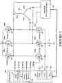
- the three-phase sensorless brushless direct current motor 100 may be electronically commutated with switching power transistors 108 and 110, e.g., power field effect transistors (one pair per phase for a three-phase motor), connected to the stator windings 102 (windings) thereof and a direct current (DC) power source (not shown).
- Back electromotive force (EMF) zero-cross detectors 104 shown for illustration but not part of the teachings herein
- a digital device 106 e.g., a microcontroller, may have PWM generators 116 that provide pulse width modulation (PWM) outputs coupled to power transistor drivers 118.
- PWM pulse width modulation
- the power transistor drivers 118 may control turn-on and turn-off of the switching power transistors 108 and 110.
- EMF back electromotive force
- the power transistors 108 and 110 may be controlled by the digital device 106 (e.g., a microcontroller) that may be coupled to the power transistors 108 and 110 through power transistor drivers 118 that may or may not be part of the digital device 106.
- the digital device 106 may provide, via the power transistor drivers 118, six pulse width modulation (PWM) outputs, PWM0-PWM5, that may control both the motor rotation direction and speed by turning on and off appropriate ones of the power transistors 108 and 110, according to PWM signals appropriately sequenced and timed.
- PWM pulse width modulation
- the digital device 106 may further comprise a voltage comparator 122, analog-to-digital converter 121 and a charge time measurement unit (CTMU) 120, as more fully described hereinafter.
- CTMU charge time measurement unit
- the measurement method may be done on a stationary or commutating motor, respectively.
- the rotor position measurements are interleaved (do not occur during a commutation period) and hence commutation and measurement may proceed in a sequential manner.
- the motor is rotated by an external force as described herein the rotor position may also be detected before commutation begins ( e.g ., using the first embodiment).
- the method and system of the first and second embodiments may be integrated into a commutation scheme commonly referred to as six step control for BLDC motors, but is not limited to that, other motor variants thereof, e.g., a permanent magnet synchronous motor (PMSM).
- PMSM permanent magnet synchronous motor
- the rotor position Prior to starting/commutating the motor the rotor position may be determined (first embodiment) and this may be used to select the switching state (starting point) in the associated six step control sequence. This effectively synchronizes the commutation sequence with the rotor position prior to start up and this has the effect of enabling efficient torque to be delivered to the motor when the commutation sequence starts. This aligns with the synchronous control nature of an electronically controlled brushless motor.
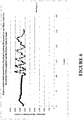
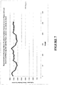
- FIGS. 5 , 6 and 7 depicted are representative measurements showing inductance change/rotor position that illustrate not only position but signal amplitude with speed and hence may be used for determination of that variable also.
- Signal processing of the measurements in the form of Clarke transformation and the trigonometric arctan function may be used to determine the rotor position (depending on the specific inductance characteristics) and speed through an effective vector representation of the measured signals. It is envisaged this may enable rotor position measurement to within one (1) mechanical degree in practice. Hence this enables more efficient commutation scheduling and thus more efficient motor operation than provided by Hall sensors which commonly provide signal change indication every 60 electrical degrees. Note that the data used for the graphs shown in Figures 5 , 6 and 7 were taken with a 12 bit analog-to-digital converter (ADC).
- ADC analog-to-digital converter
- Commutation and measurement of rotor position may proceed in a sequential manner and this affords the motor to be commutated at a less frequent rate (a pulsed type commutation) which may enable low power consumption modes of operation to be realized.
- a pulsed type commutation E.g., whereby the motor operation is desired to produce rotation at low speed but full torque is not required by the application. It would suit, for example, systems where a large inertial load, like a flywheel, is deployed with low overall friction. Hence, once rotating the load and low friction enable it to keep turning without continuous commutation.
- commutation is used to start and keep the motor rotating and in-between commutations the measurement of speed and position ensues until the next commutation point is scheduled.
- commutation does not need to be the next in the logical six-step control sequence.
- Another example is a fan required to run at low speed and therefore reduced torque.
- This type of operation may also mitigate the effects of having a stationary motor for long time periods whereby stiction and build-up of contaminants in some situations may affect motor reliability.
- knowing the rotor position and speed through these measurements offers the ability to brake the motor rotor at a certain position. Hence this may be coupled for example with a pulsed commutation mode to achieve a position control system. Therefore this type of system may enable replacement of stepper motors using a lower cost BLDC motor for appropriate applications.
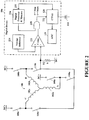
- FIG. 2 depicted is a simplified schematic diagram of the three-phase sensorless brushless direct current motor and electronically commutating motor controller shown in Figure 1 , according to a specific example embodiment of this disclosure.
- This circuit arrangement may be used for determining the position of a permanent magnet rotor at rest and at low speed without additional hardware or the back EMF zero-cross detectors 104 ( Figure 1 ).
- the power transistors 108 and 110 are shown as switches 108 and 110, respectively, for simplification in describing herein circuit operation thereof.
- the switches 108 couple the motor stator windings 102 to DC+, and the switches 110 couple the motor stator windings 102 to a current sensing device 112, e.g., a resistor (shown for ease of explanation), that completes the winding current path from DC+ to DC-.
- Current through the current sensing device 112 may create a voltage that is proportional to this current and may be coupled to a first input, e.g., negative input, of the voltage comparator 122.
- any type of current sensing device may be used, e.g., current transformer and parallel connected resistor, etc., to generate a voltage, besides just a resistor.
- One having ordinary skill in electronics and power systems design and the benefit of this disclosure could readily select such a current sensing device in combination with a device that may convert the sensed current into a representative voltage.
- the digital device 106 may further comprise a voltage reference 224, an AND gate 228 and a digital processor and memory 226.
- the voltage reference 224 may be coupled to a second input, e.g., positive input, of the voltage comparator 122 and may provide a reference voltage thereto. When the voltage across the current sensing device 112 is less than the reference voltage, the output of the comparator 122 will be at a logic high ("1"). When the voltage across the current sensing device 112 is equal to or greater than the reference voltage, the output of the comparator 122 will be at a logic low ("0").
- the CTMU 120 may start timing when both inputs of the AND gate 228 are at logic highs ("1"), and stop timing when the comparator 122 output goes to a logic low (“0").
- a selectable constant current (not shown but integrated within the CTMU 120) is passed into the external capacitor 114 allowing it to be charged at a specific rate according to the requirements of the application.
- the resulting voltage represents the time taken to charge the capacitor 114. This voltage may be converted by the internal ADC 121 for subsequent processing by the digital processor 226.
- the CTMU 120 provides precise time measurements that may be started when a logic high ("1") is applied to a control input 232 thereto. When a logic low (“0") is applied to the control input 232 of the CTMU 120 the timing thereof stops.
- An external timing capacitor 114 may be provided as part of the CTMU 120 timing function.
- the digital processor 226 may initiate the CTMU 120 timing as well as reset this time, while also controlling operation of the switches 108 and 110, as more fully described hereinafter.
- a representative CTMU Based measurement timing trace is shown in Figure 9 for reference purposes. This depicts a measurement pulse applied to the CTMU 120 and motor phase selected for measurement simultaneously. The rise of motor phase current is shown while the pulse is applied and the arising voltage on the CTMU external capacitor 114.
- the measurement entails the monitoring of the time taken for the Comparator 122 reference level to be exceeded by the converted voltage (representing motor phase current) by the sensing device 112.
- the resulting voltage on the CTMU capacitor represents this time and is converted by the ADC 121 for subsequent signal processing. It is contemplated and within the scope of this disclosure that various other logic combination for control of the CTMU 120 may be used with equal results.
- One having ordinary skill in the art of digital circuit design and the benefit of this disclosure could easily come up with alternate designs that would be covered under the spirit and intent of this disclosure.
- Full current I passes through stator winding 102a and the sum of the currents passing through stator windings 102b and 102c equal current I.
- Current I also passes through the current sensing device 112 to produce a time dependent voltage V that may be coupled to an input of the voltage comparator 122.
- the digital device 106 may close switches 108b, 108c and 110a wherein stator windings 102b and 102c are coupled in parallel and to the high side voltage DC+.
- This parallel connected combination of stator windings is further coupled in series with the stator winding 102a that is also coupled to the low side voltage DC- through the current sensing device 112.
- Full current I passes through stator winding 102a and the sum of the currents passing through stator windings 102b and 102c equal current I.
- Current I also passes through the current sensing device 112 to produce a time dependent voltage V that may be coupled to an input of the voltage comparator 122.
- Inductance resists current change according to the aforementioned formula, therefore most of the applied voltage will be directly across the inductor L and very little current will flow through the inductor L and the resistor R at the first instance of voltage applied thereto.
- the inductor L may be parallel/series connected stator windings 102, and the resistor R may be the current sensing device 112 described hereinabove.
- FIG. 2B depicted is a simplified schematic diagram of third and fourth switch configurations for stator winding excitation to measure inductance thereof in the three-phase sensorless brushless direct current motor shown in Figures 1 and 2 , according to the teachings of this disclosure.
- the digital device 106 may close switches 108b, 110a and 110c wherein stator windings 102a and 102c are coupled in parallel and to the low side voltage DC- through the current sensing device 112. This parallel connected combination of stator windings is further coupled in series with the stator winding 102b that is also coupled to the high side voltage DC+.
- FIG. 2C depicted is a simplified schematic diagram of fifth and sixth switch configurations for stator winding excitation to measure inductance thereof in the three-phase sensorless brushless direct current motor shown in Figures 1 and 2 , according to the teachings of this disclosure.
- the digital device 106 may close switches 108c, 110a and 110b wherein stator windings 102a and 102b are coupled in parallel and to the low side voltage DC- through the current sensing device 112. This parallel connected combination of stator windings is further coupled in series with the stator winding 102c that is also coupled to the high side voltage DC+.
- Example time variations, for a small fan motor, in which the voltage across the current sensing device 112 rises to the reference voltage for the various above referenced switch configuration states, as a function of the permanent magnet rotor position within the 60 electrical degree sectors, are summarized in the following Table II. Note that motor construction and also the measurement circuit scaling components will dictate the time which may be optimized for specific requirements, so this is for example only.
- Table III Phase Sector 1 Sector 2 Sector 3 Sector 4 Sector 5 Sector 6 A Ta+ > Ta- Ta+ > Ta- Ta+ ⁇ Ta- Ta+ ⁇ Ta- Ta+ ⁇ Ta- Ta+ > Ta- B Tb+ ⁇ Tb- Tb+ > Tb- Tb+ > Tb- Tb+ > Tb- Tb+ > Tb- Tb+ > Tb- Tb+ > Tb- Tb+ > Tb- Tb+ > Tb- Tb+ ⁇ Tb- C Tc+ ⁇ Tc- Tc+ ⁇ Tc- Tc+ >Tc- Tc+ > Tc- Tc+ > Tc- Tc+ > Tc- Tc+ > Tc- Tc+ > Tc- Tc+ > Tc- Tc+ > Tc- Tc+ > Tc- Tc+ > Tc- Tc+ > Tc- Tc+ > Tc- Tc+ > Tc- Tc+ > Tc- Tc+ > Tc- Tc+ > Tc- Tc+
Landscapes
- Engineering & Computer Science (AREA)
- Power Engineering (AREA)
- Control Of Motors That Do Not Use Commutators (AREA)
Claims (14)
- Procédé de détermination de la position d'un rotor d'un moteur polyphasé synchrone (100), ledit procédé comprenant les étapes suivantes :coupler les combinaisons de tous les enroulements de la pluralité d'enroulements de stator (A, B, C), sauf un, à une première tension (DC+ ; DC-) ;coupler les enroulements restants de la pluralité d'enroulements de stator (A, B, C) à une seconde tension (DC+ ; DC-) ;mesurer les premiers instants où les courants dans toutes les combinaisons de la pluralité d'enroulements de stator (A, B, C) sont égaux à un courant de référence (224) ; etdéterminer la position du rotor à partir des premiers instants mesurés, etcoupler les combinaisons de tous les enroulements de la pluralité d'enroulements de stator (A, B, C), sauf un, à la seconde tension (DC+ ; DC-) ;coupler les enroulements restants de la pluralité d'enroulements de stator (A, B, C) à la première tension (DC+ ; DC-) ;mesurer les seconds instants où les courants dans toutes les combinaisons de la pluralité d'enroulements de stator (A, B, C) sont égaux au courant de référence (224) ; etdéterminer la position du rotor à partir des premiers et seconds instants mesurés,où les premiers et seconds instants mesurés pour chacun des enroulements restants de la pluralité d'enroulements de stator (A, B, C), sont des paires de mesures d'instants de phase ;caractérisé en ce quela paire de mesure d'instants de phase présentant la plus grande valeur absolue de la différence entre les premier et second instants mesurés de la paire de mesures d'instants de phase, et son signe, représentent la position du rotor.
- Procédé selon la revendication 1, où le moteur polyphasé est un moteur triphasé, où pour déterminer les premiers instants :les combinaisons de deux des trois enroulements de stator (A, B, C) sont couplées à la première tension (DC+ ; DC-) ;les troisièmes des trois enroulements de stator (A, B, C) sont couplés à la seconde tension (DC- ; DC+) ;les premiers instants sont mesurés lorsque les courants dans toutes les combinaisons des trois enroulements de stator (A, B, C) sont égaux à un courant de référence (224) ;et où pour déterminer les seconds instants :les combinaisons de deux des trois enroulements de stator (A, B, C) sont couplées à la seconde tension (DC- ; DC+) ;les troisièmes des trois enroulements de stator (A, B, C) sont couplés à la première tension (DC+ ; DC-) ; etles seconds instants sont mesurés lorsque les courants dans toutes les combinaisons des trois enroulements de stator (A, B, C) sont égaux au courant de référence (224).
- Procédé selon la revendication 2, où la position du rotor est dans un secteur électrique associé à la paire de mesures d'instants de phase présentant la plus grande valeur absolue d'une différence entre eux.
- Procédé selon la revendication 3, où le secteur électrique comprend 60 degrés électriques, et est l'un de six secteurs électriques comprenant 360 degrés électriques.
- Procédé selon la revendication 4, où :les trois enroulements de stator sont représentés par la phase A, la phase B et la phase C;le premier instant mesuré pour l'enroulement de stator de la phase A est Ta+ ;le second instant mesuré pour l'enroulement de stator de la phase A est Ta- ;le premier instant mesuré pour l'enroulement de stator de la phase B est Tb+ ;le second instant mesuré pour l'enroulement de stator de la phase B est Tb- ;le premier instant mesuré pour l'enroulement de stator de la phase C est Tc+ ;le second instant mesuré pour l'enroulement de stator de la phase C est Tc- ; etle secteur électrique est déterminé par
phase Secteur 1 Secteur 2 Secteur 3 Secteur 4 Secteur 5 Secteur 6 A Ta+ > Ta- Ta+ > Ta- Ta+ < Ta- Ta+ < Ta- Ta+ < Ta- Ta+ > Ta- B Tb+ < Tb- Tb+ > Tb- Tb+ > Tb- Tb+ > Tb- Tb+ < Tb- Tb+ < Tb- C Tc+ < Tc- Tc+ < Tc- Tc+ < Tc- Tc+ >Tc- Tc+ > Tc- Tc+ > Tc- - Procédé selon l'une quelconque des revendications précédentes, où la seconde tension est plus positive que la première tension, ou, où la première tension est plus positive que la seconde tension.
- Procédé selon l'une quelconque des revendications précédentes, où les courants sont convertis en tensions, et les premiers et seconds instants mesurés sont les instants où les tensions converties sont égales à une tension de référence (224).
- Procédé selon l'une quelconque des revendications précédentes, où les premiers et seconds instants sont mesurés avec une unité de mesure du temps de charge CTMU (120), où la CTMU (120) génère de préférence des tensions de synchronisation proportionnelles aux premiers et seconds instants, qui sont converties de préférence en leurs représentations numériques par un convertisseur analogique - numérique ADC (121), et où, de préférence, les représentations numériques proportionnelles aux premiers et seconds instants mesurés, sont traitées dans un processeur numérique (226) pour déterminer la position du rotor.
- Procédé selon la revendication 8, où la CTMU (120), l'ADC (121) et le processeur numérique (226) sont disposés dans un microcontrôleur (106).
- Procédé selon l'une quelconque des revendications précédentes, où le moteur triphasé synchrone (100) est un moteur à courant continu sans balais (BLDG) ou un moteur synchrone à aimants permanents (PMSM).
- Procédé selon l'une quelconque des revendications précédentes, où les premiers et seconds instants sont mesurés quand les impulsions de puissance ne sont pas couplées aux enroulements de stator (A, B, C).
- Procédé selon l'une quelconque des revendications précédentes, où les premiers instants mesurés sont plus courts que les instants où les troisièmes des trois enroulements de stator (A, B, C) sont couplés à la seconde tension, et / ou, où les seconds instants mesurés sont plus courts que les instants où les troisièmes des trois enroulements de stator (A, B, C) sont couplés à la première tension.
- Système de détermination de la position d'un rotor d'un moteur synchrone, ledit système comprenant :un microcontrôleur (106) comprenantun processeur numérique et une mémoire (226),une unité de mesure du temps de charge CTMU (120) couplée au processeur numérique (226) et configurée pour être couplée à un condensateur de synchronisation (114),un convertisseur analogique - numérique (ADC) (121) a couplé à la CTMU (120),un comparateur analogique (122) couplé à la CTMU (120), etune référence de tension (224) couplée à une première entrée du comparateur analogique (122) ;un moteur synchrone (100) commandé par un pont de puissance comprenant une pluralité de commutateurs de puissance (108, 110) pour coupler les enroulements de stator (A, B, C) du moteur synchrone (100) à une source d'alimentation (DC+, DC-) ;un dispositif de retour du courant (112) couplé entre certains des commutateurs de puissance (110) et la source d'alimentation (DC-) ;une seconde entrée du comparateur analogique (122) couplée au dispositif de retour du courant (112), où le dispositif de retour du courant (112) fournit une tension à la seconde entrée du comparateur analogique (122) proportionnelle au courant qui traverse les enroulements de stator (A, B, C) du moteur synchrone (122) ;où le microcontrôleur (106) est couplé aux commutateur de puissance (108, 110) pour exécuter le procédé selon l'une quelconque des revendications précédentes.
- Système selon la revendication 13, où les tensions de charge du condensateur de synchronisation (114) sont représentatives des instants de charge du courant d'enroulement.
Applications Claiming Priority (3)
| Application Number | Priority Date | Filing Date | Title |
|---|---|---|---|
| US201361766763P | 2013-02-20 | 2013-02-20 | |
| US14/183,642 US9525372B2 (en) | 2013-02-20 | 2014-02-19 | Method and system for determining the position of a synchronous motor's rotor |
| PCT/US2014/017247 WO2014130601A2 (fr) | 2013-02-20 | 2014-02-20 | Procédé et système permettant de déterminer la position d'un rotor d'un moteur synchrone |
Publications (2)
| Publication Number | Publication Date |
|---|---|
| EP2959573A2 EP2959573A2 (fr) | 2015-12-30 |
| EP2959573B1 true EP2959573B1 (fr) | 2019-05-22 |
Family
ID=51350701
Family Applications (1)
| Application Number | Title | Priority Date | Filing Date |
|---|---|---|---|
| EP14708421.4A Active EP2959573B1 (fr) | 2013-02-20 | 2014-02-20 | Procédé et système permettant de déterminer la position d'un rotor d'un moteur synchrone |
Country Status (6)
| Country | Link |
|---|---|
| US (1) | US9525372B2 (fr) |
| EP (1) | EP2959573B1 (fr) |
| KR (1) | KR20150122701A (fr) |
| CN (1) | CN105531917B (fr) |
| TW (1) | TWI625038B (fr) |
| WO (1) | WO2014130601A2 (fr) |
Cited By (1)
| Publication number | Priority date | Publication date | Assignee | Title |
|---|---|---|---|---|
| DE102023127018A1 (de) * | 2023-10-04 | 2025-04-10 | FETtec UG (haftungsbeschränkt) | System und Verfahren zur Ansteuerung eines Elektromotors |
Families Citing this family (57)
| Publication number | Priority date | Publication date | Assignee | Title |
|---|---|---|---|---|
| RU2594358C1 (ru) * | 2015-05-27 | 2016-08-20 | Закрытое акционерное общество "Орбита" | Способ бездатчикового определения начального положения ротора синхронного электродвигателя с постоянными магнитами |
| US9748878B1 (en) * | 2015-08-18 | 2017-08-29 | Marvell International, Ltd. | Adaptive brake timing for a brushless motor |
| TWI563791B (en) * | 2015-11-17 | 2016-12-21 | En Technologies Corp | System and way for no sensor three-phase motor |
| TWI609568B (zh) * | 2015-12-18 | 2017-12-21 | 陞達科技股份有限公司 | 馬達控制系統及其方法 |
| CN105529972A (zh) * | 2016-02-24 | 2016-04-27 | 核工业理化工程研究院 | 中频小电流的检测电路 |
| CN105515475A (zh) * | 2016-02-24 | 2016-04-20 | 核工业理化工程研究院 | 基于buck变换器的高速无刷直流电机控制器 |
| CN105529963A (zh) * | 2016-02-24 | 2016-04-27 | 核工业理化工程研究院 | 高速无刷直流电机换相滞后角软件补偿方法 |
| CN105553346A (zh) * | 2016-02-24 | 2016-05-04 | 核工业理化工程研究院 | 降压型直流变换装置 |
| CN105529971A (zh) * | 2016-02-24 | 2016-04-27 | 核工业理化工程研究院 | 应用高速无刷直流电机换相滞后角软件补偿方法的控制系统 |
| US10298099B2 (en) * | 2016-02-29 | 2019-05-21 | Dana Automotive Systems Group, Llc | Method of sensor misalignment learning for motor speed estimation |
| CN105790666A (zh) * | 2016-04-11 | 2016-07-20 | 南京信息工程大学 | 基于霍尔信号的无刷直流电机直接转矩控制系统和方法 |
| TWI679840B (zh) * | 2016-06-07 | 2019-12-11 | 廣明光電股份有限公司 | 馬達控制角度的決定方法 |
| CN106059402A (zh) * | 2016-06-13 | 2016-10-26 | 苏州灵动智能装备有限责任公司 | 一种无位置传感器直流无刷电机的调速方法 |
| US10116243B2 (en) * | 2016-06-16 | 2018-10-30 | Allegro Microsystems, Llc | Determining motor position with complementary drive and detect and slight move |
| US10181810B2 (en) * | 2016-06-16 | 2019-01-15 | Allegro Microsystems, Llc | Determining motor position with complementary driving and detection and current injection |
| WO2018010130A1 (fr) * | 2016-07-14 | 2018-01-18 | SZ DJI Technology Co., Ltd. | Dispositif de commande de moteur programmable utilisant un moteur |
| US9831809B1 (en) * | 2016-07-20 | 2017-11-28 | Semiconductor Components Industries, Llc | Rotor position sensing system for three phase motors and related methods |
| US9831808B1 (en) * | 2016-07-20 | 2017-11-28 | Semiconductor Components Industries, Llc | Rotor position sensing system for three phase motors and related methods |
| CN107659234A (zh) * | 2016-07-25 | 2018-02-02 | 半导体元件工业有限责任公司 | 三相电机的转子位置感测系统以及相关方法 |
| US9991796B2 (en) * | 2016-07-26 | 2018-06-05 | Fuji Electric Co., Ltd. | Switch drive circuit |
| JP6284207B1 (ja) * | 2016-11-08 | 2018-02-28 | 北斗制御株式会社 | 電動機の界磁位置検出方法 |
| DE102017127410A1 (de) * | 2016-11-22 | 2018-05-24 | Schaeffler Technologies AG & Co. KG | Verfahren und Schaltungsanordnung zur Ermittlung der Stellung eines Rotors eines Elektromotors |
| US9876452B1 (en) | 2016-12-16 | 2018-01-23 | Semiconductor Components Industries, Llc | Rotor position sensing system for permanent magnet synchronous motors and related methods |
| WO2018141394A1 (fr) * | 2017-02-03 | 2018-08-09 | Arcelik Anonim Sirketi | Appareil électroménager à mécanisme de commande sans capteur de moteur cc sans balai |
| US10454398B2 (en) * | 2017-04-28 | 2019-10-22 | Flir Surveillance, Inc. | Systems and methods for control of electric motors |
| JP6469171B2 (ja) * | 2017-06-14 | 2019-02-13 | ファナック株式会社 | 電動機の制御装置 |
| TWI652892B (zh) | 2017-07-05 | 2019-03-01 | 茂達電子股份有限公司 | 三相馬達的轉子位置偵測裝置與偵測方法 |
| US10218296B1 (en) | 2017-08-29 | 2019-02-26 | Semiconductor Components Industries, Llc | Rotor position sensing system for three phase motors and related methods |
| CN107359830B (zh) * | 2017-09-08 | 2020-07-17 | 中颖电子股份有限公司 | 一种用于三相无刷直流电机的转子定位方法 |
| CN108631660B (zh) * | 2018-03-30 | 2020-04-10 | 江苏美的清洁电器股份有限公司 | 无刷直流电机的转子定位方法、定位装置和控制系统 |
| US10897217B2 (en) * | 2018-08-21 | 2021-01-19 | Caterpillar Inc. | Switched reluctance motor control system |
| TWI672901B (zh) * | 2018-10-03 | 2019-09-21 | 茂達電子股份有限公司 | 自動偵測馬達轉子起始位置的裝置及方法 |
| GB2582612B (en) * | 2019-03-28 | 2021-10-13 | Dyson Technology Ltd | A method of determining a position of a rotor of a brushless permanent magnet motor |
| CN113785485B (zh) | 2019-04-15 | 2025-10-10 | 米沃奇电动工具公司 | 电动工具的无传感器电机控制 |
| US11575336B2 (en) * | 2019-05-31 | 2023-02-07 | Nxp Usa, Inc. | Technique for on-the-fly start-up of a permanent magnet AC motor without a speed or position sensor |
| EP4489291A3 (fr) | 2019-06-10 | 2025-03-12 | Black & Decker, Inc. | Commande de moteur sans balai sans capteur à orientation de champ dans un outil électrique |
| TWI697194B (zh) * | 2019-07-04 | 2020-06-21 | 微星科技股份有限公司 | 永磁馬達轉子位置偵測裝置及其方法 |
| KR102396561B1 (ko) * | 2019-07-15 | 2022-05-10 | 엘지전자 주식회사 | 모터 구동 장치 및 그 제어 방법 |
| CN110690839B (zh) * | 2019-09-29 | 2021-05-25 | 大连海事大学 | 一种六相永磁容错轮缘推进电机拓扑控制方法 |
| US11465511B2 (en) * | 2020-01-14 | 2022-10-11 | Ford Global Technologies, Llc | Systems and methods to determine and validate torque of an electric machine |
| CN114079408B (zh) * | 2020-08-20 | 2025-08-05 | 恩智浦美国有限公司 | 电动机的初始位置检测 |
| TWI793517B (zh) * | 2021-02-05 | 2023-02-21 | 陞達科技股份有限公司 | 馬達系統及馬達驅動方法 |
| US12227168B2 (en) * | 2021-03-31 | 2025-02-18 | Sensata Technologies, Inc. | Accurate error estimation in E-motor sensors |
| US11563397B2 (en) | 2021-04-08 | 2023-01-24 | Global Mixed-Mode Technology Inc. | Motor controller |
| TWI764663B (zh) * | 2021-04-08 | 2022-05-11 | 致新科技股份有限公司 | 馬達控制器 |
| US11557992B2 (en) | 2021-05-14 | 2023-01-17 | Delphi Technologies Ip Limited | Systems and methods for phase-voltage based motor period measurement and controlled signal path fault detection |
| CN113326673B (zh) * | 2021-06-23 | 2023-08-22 | 华北电力大学 | 一种同步电机的vbr模型电磁暂态仿真方法及系统 |
| CN113922718A (zh) * | 2021-09-07 | 2022-01-11 | 山东大学 | 电机的驱动控制方法及系统 |
| US11705835B2 (en) * | 2021-10-19 | 2023-07-18 | Hamilton Sundstrand Corporation | Sensorless position determination of an electric machine |
| CN113965114A (zh) * | 2021-11-16 | 2022-01-21 | 江苏科技大学 | 一种无刷直流电机转子位置的初始扇区检测方法 |
| CN114640274B (zh) * | 2022-04-02 | 2025-08-15 | 成都芯源系统有限公司 | 无刷直流电机系统及其逻辑控制电路和初始转向判断方法 |
| GB2619694B (en) * | 2022-04-26 | 2025-05-07 | Dyson Technology Ltd | A method of controlling a brushless permanent magnet motor |
| CN114732300A (zh) * | 2022-04-29 | 2022-07-12 | 深圳朗特智能控制股份有限公司 | 一种食物处理设备及其食物处理方法 |
| KR102672141B1 (ko) * | 2022-05-17 | 2024-06-03 | 한국기술교육대학교 산학협력단 | 홀 센서 기반의 로터 위치 추정 시스템 및 방법 |
| CN117639568A (zh) * | 2022-08-12 | 2024-03-01 | 丹佛斯(天津)有限公司 | 用于检测电机的转子的初始位置的方法和装置 |
| CN116085295B (zh) * | 2023-04-12 | 2023-07-25 | 广东美的暖通设备有限公司 | 压缩机启动状态检测方法、装置及离心压缩机 |
| US12549115B2 (en) | 2023-09-29 | 2026-02-10 | Stmicroelectronics International N.V. | Systems, apparatuses, and methods to perform startup step detection in an internal permanent magnet synchronous machine |
Family Cites Families (8)
| Publication number | Priority date | Publication date | Assignee | Title |
|---|---|---|---|---|
| DE10162380A1 (de) * | 2001-12-19 | 2003-07-03 | Bosch Gmbh Robert | Verfahren zum Starten eines bürstenlosen Gleichstrommotors |
| JP3875188B2 (ja) * | 2002-12-16 | 2007-01-31 | 株式会社ジェイテクト | 電動モータ装置 |
| US7460441B2 (en) | 2007-01-12 | 2008-12-02 | Microchip Technology Incorporated | Measuring a long time period |
| GB0707672D0 (en) | 2007-04-20 | 2007-05-30 | Melexis Nv | Rotor orientation detection in brushless dc motors |
| US7764213B2 (en) | 2008-07-01 | 2010-07-27 | Microchip Technology Incorporated | Current-time digital-to-analog converter |
| US8421399B2 (en) * | 2008-10-24 | 2013-04-16 | Energy Innovative Products, Llc | Energy saver delay circuit for AC induction motors |
| CN102045020B (zh) * | 2011-01-24 | 2013-01-23 | 东元总合科技(杭州)有限公司 | 永磁电机转子位置检测方法 |
| CN102497140A (zh) * | 2011-12-13 | 2012-06-13 | 上海电气集团股份有限公司 | 一种永磁同步电机无传感器控制算法 |
-
2014
- 2014-02-19 US US14/183,642 patent/US9525372B2/en active Active
- 2014-02-20 KR KR1020157025862A patent/KR20150122701A/ko not_active Ceased
- 2014-02-20 TW TW103105710A patent/TWI625038B/zh active
- 2014-02-20 CN CN201480009522.6A patent/CN105531917B/zh active Active
- 2014-02-20 WO PCT/US2014/017247 patent/WO2014130601A2/fr not_active Ceased
- 2014-02-20 EP EP14708421.4A patent/EP2959573B1/fr active Active
Non-Patent Citations (1)
| Title |
|---|
| None * |
Cited By (1)
| Publication number | Priority date | Publication date | Assignee | Title |
|---|---|---|---|---|
| DE102023127018A1 (de) * | 2023-10-04 | 2025-04-10 | FETtec UG (haftungsbeschränkt) | System und Verfahren zur Ansteuerung eines Elektromotors |
Also Published As
| Publication number | Publication date |
|---|---|
| CN105531917B (zh) | 2018-02-06 |
| WO2014130601A2 (fr) | 2014-08-28 |
| TW201448448A (zh) | 2014-12-16 |
| WO2014130601A3 (fr) | 2015-11-19 |
| EP2959573A2 (fr) | 2015-12-30 |
| KR20150122701A (ko) | 2015-11-02 |
| CN105531917A (zh) | 2016-04-27 |
| US20140232311A1 (en) | 2014-08-21 |
| TWI625038B (zh) | 2018-05-21 |
| US9525372B2 (en) | 2016-12-20 |
Similar Documents
| Publication | Publication Date | Title |
|---|---|---|
| EP2959573B1 (fr) | Procédé et système permettant de déterminer la position d'un rotor d'un moteur synchrone | |
| US9071172B2 (en) | Sine modified trapezoidal drive for brushless DC motors | |
| CN102577086B (zh) | 无传感器无刷直流马达中用于减少零交叉粒度的可变脉宽调制 | |
| CN102577084B (zh) | 通过门控脉宽调制驱动的无刷直流马达的慢速操作 | |
| JP6284207B1 (ja) | 電動機の界磁位置検出方法 | |
| JP2018508171A (ja) | Bldc適応ゼロ交差検出 | |
| CN112747662B (zh) | 电动机的磁场位置检测方法 | |
| CN112088486A (zh) | 马达的操作模式控制 | |
| US9906175B2 (en) | Method of starting a three-phase BLDC motor and motor driver using same | |
| CN100420143C (zh) | 无刷直流马达的控制方法及控制电路 | |
| US20070159124A1 (en) | Electric Motor with Adjustable Timing | |
| KR20150031356A (ko) | Bldc 모터 제어 시스템에서 역기전력의 제로 크로싱 지점 판단 기준전압 보상 장치 및 방법 | |
| CN120237989A (zh) | 电动机的励磁位置检测方法 | |
| CN120320641A (zh) | 电动机的励磁位置检测方法 | |
| US20180219500A1 (en) | 2-phase brushless ac motor with embedded electronic control | |
| Wang et al. | Sensorless control technology for single phase BLDCM based on the winding time-sharing method | |
| CN110620459B (zh) | 用于操作bldc电动机的驱动电路 | |
| Zhang et al. | Position sensorless control for permanent-magnet brushless DC motor based on ASIC ML4425 | |
| JPWO2016194835A1 (ja) | 直流ブラシレスモータ制御装置 | |
| JP7749043B2 (ja) | 電動機の界磁位置検出方法 | |
| WO2022226579A1 (fr) | Commutation électronique d'un moteur sans balais et sans capteur | |
| Lai et al. | Quasi-sinusoidal voltage source driver design for brushless DC motor with digital hall sensor feedback |
Legal Events
| Date | Code | Title | Description |
|---|---|---|---|
| PUAI | Public reference made under article 153(3) epc to a published international application that has entered the european phase |
Free format text: ORIGINAL CODE: 0009012 |
|
| 17P | Request for examination filed |
Effective date: 20150917 |
|
| AK | Designated contracting states |
Kind code of ref document: A2 Designated state(s): AL AT BE BG CH CY CZ DE DK EE ES FI FR GB GR HR HU IE IS IT LI LT LU LV MC MK MT NL NO PL PT RO RS SE SI SK SM TR |
|
| AX | Request for extension of the european patent |
Extension state: BA ME |
|
| DAX | Request for extension of the european patent (deleted) | ||
| REG | Reference to a national code |
Ref country code: DE Ref legal event code: R079 Ref document number: 602014047162 Country of ref document: DE Free format text: PREVIOUS MAIN CLASS: H02P0006180000 Ipc: H02K0029120000 |
|
| RIC1 | Information provided on ipc code assigned before grant |
Ipc: H02P 21/00 20160101ALI20181129BHEP Ipc: H02P 6/18 20160101ALI20181129BHEP Ipc: H02K 29/12 20060101AFI20181129BHEP Ipc: H02P 6/185 20160101ALI20181129BHEP |
|
| GRAP | Despatch of communication of intention to grant a patent |
Free format text: ORIGINAL CODE: EPIDOSNIGR1 |
|
| STAA | Information on the status of an ep patent application or granted ep patent |
Free format text: STATUS: GRANT OF PATENT IS INTENDED |
|
| INTG | Intention to grant announced |
Effective date: 20190104 |
|
| RIC1 | Information provided on ipc code assigned before grant |
Ipc: H02K 29/12 20060101AFI20181129BHEP Ipc: H02P 6/18 20160101ALI20181129BHEP Ipc: H02P 21/00 20160101ALI20181129BHEP Ipc: H02P 6/185 20160101ALI20181129BHEP |
|
| GRAS | Grant fee paid |
Free format text: ORIGINAL CODE: EPIDOSNIGR3 |
|
| GRAA | (expected) grant |
Free format text: ORIGINAL CODE: 0009210 |
|
| STAA | Information on the status of an ep patent application or granted ep patent |
Free format text: STATUS: THE PATENT HAS BEEN GRANTED |
|
| AK | Designated contracting states |
Kind code of ref document: B1 Designated state(s): AL AT BE BG CH CY CZ DE DK EE ES FI FR GB GR HR HU IE IS IT LI LT LU LV MC MK MT NL NO PL PT RO RS SE SI SK SM TR |
|
| REG | Reference to a national code |
Ref country code: GB Ref legal event code: FG4D |
|
| REG | Reference to a national code |
Ref country code: CH Ref legal event code: EP |
|
| REG | Reference to a national code |
Ref country code: IE Ref legal event code: FG4D |
|
| REG | Reference to a national code |
Ref country code: DE Ref legal event code: R096 Ref document number: 602014047162 Country of ref document: DE |
|
| REG | Reference to a national code |
Ref country code: AT Ref legal event code: REF Ref document number: 1137284 Country of ref document: AT Kind code of ref document: T Effective date: 20190615 |
|
| REG | Reference to a national code |
Ref country code: NL Ref legal event code: MP Effective date: 20190522 |
|
| REG | Reference to a national code |
Ref country code: LT Ref legal event code: MG4D |
|
| PG25 | Lapsed in a contracting state [announced via postgrant information from national office to epo] |
Ref country code: LT Free format text: LAPSE BECAUSE OF FAILURE TO SUBMIT A TRANSLATION OF THE DESCRIPTION OR TO PAY THE FEE WITHIN THE PRESCRIBED TIME-LIMIT Effective date: 20190522 Ref country code: NO Free format text: LAPSE BECAUSE OF FAILURE TO SUBMIT A TRANSLATION OF THE DESCRIPTION OR TO PAY THE FEE WITHIN THE PRESCRIBED TIME-LIMIT Effective date: 20190822 Ref country code: HR Free format text: LAPSE BECAUSE OF FAILURE TO SUBMIT A TRANSLATION OF THE DESCRIPTION OR TO PAY THE FEE WITHIN THE PRESCRIBED TIME-LIMIT Effective date: 20190522 Ref country code: SE Free format text: LAPSE BECAUSE OF FAILURE TO SUBMIT A TRANSLATION OF THE DESCRIPTION OR TO PAY THE FEE WITHIN THE PRESCRIBED TIME-LIMIT Effective date: 20190522 Ref country code: FI Free format text: LAPSE BECAUSE OF FAILURE TO SUBMIT A TRANSLATION OF THE DESCRIPTION OR TO PAY THE FEE WITHIN THE PRESCRIBED TIME-LIMIT Effective date: 20190522 Ref country code: PT Free format text: LAPSE BECAUSE OF FAILURE TO SUBMIT A TRANSLATION OF THE DESCRIPTION OR TO PAY THE FEE WITHIN THE PRESCRIBED TIME-LIMIT Effective date: 20190922 Ref country code: AL Free format text: LAPSE BECAUSE OF FAILURE TO SUBMIT A TRANSLATION OF THE DESCRIPTION OR TO PAY THE FEE WITHIN THE PRESCRIBED TIME-LIMIT Effective date: 20190522 Ref country code: ES Free format text: LAPSE BECAUSE OF FAILURE TO SUBMIT A TRANSLATION OF THE DESCRIPTION OR TO PAY THE FEE WITHIN THE PRESCRIBED TIME-LIMIT Effective date: 20190522 Ref country code: NL Free format text: LAPSE BECAUSE OF FAILURE TO SUBMIT A TRANSLATION OF THE DESCRIPTION OR TO PAY THE FEE WITHIN THE PRESCRIBED TIME-LIMIT Effective date: 20190522 |
|
| PG25 | Lapsed in a contracting state [announced via postgrant information from national office to epo] |
Ref country code: BG Free format text: LAPSE BECAUSE OF FAILURE TO SUBMIT A TRANSLATION OF THE DESCRIPTION OR TO PAY THE FEE WITHIN THE PRESCRIBED TIME-LIMIT Effective date: 20190822 Ref country code: RS Free format text: LAPSE BECAUSE OF FAILURE TO SUBMIT A TRANSLATION OF THE DESCRIPTION OR TO PAY THE FEE WITHIN THE PRESCRIBED TIME-LIMIT Effective date: 20190522 Ref country code: LV Free format text: LAPSE BECAUSE OF FAILURE TO SUBMIT A TRANSLATION OF THE DESCRIPTION OR TO PAY THE FEE WITHIN THE PRESCRIBED TIME-LIMIT Effective date: 20190522 Ref country code: GR Free format text: LAPSE BECAUSE OF FAILURE TO SUBMIT A TRANSLATION OF THE DESCRIPTION OR TO PAY THE FEE WITHIN THE PRESCRIBED TIME-LIMIT Effective date: 20190823 |
|
| REG | Reference to a national code |
Ref country code: AT Ref legal event code: MK05 Ref document number: 1137284 Country of ref document: AT Kind code of ref document: T Effective date: 20190522 |
|
| PG25 | Lapsed in a contracting state [announced via postgrant information from national office to epo] |
Ref country code: RO Free format text: LAPSE BECAUSE OF FAILURE TO SUBMIT A TRANSLATION OF THE DESCRIPTION OR TO PAY THE FEE WITHIN THE PRESCRIBED TIME-LIMIT Effective date: 20190522 Ref country code: SK Free format text: LAPSE BECAUSE OF FAILURE TO SUBMIT A TRANSLATION OF THE DESCRIPTION OR TO PAY THE FEE WITHIN THE PRESCRIBED TIME-LIMIT Effective date: 20190522 Ref country code: AT Free format text: LAPSE BECAUSE OF FAILURE TO SUBMIT A TRANSLATION OF THE DESCRIPTION OR TO PAY THE FEE WITHIN THE PRESCRIBED TIME-LIMIT Effective date: 20190522 Ref country code: EE Free format text: LAPSE BECAUSE OF FAILURE TO SUBMIT A TRANSLATION OF THE DESCRIPTION OR TO PAY THE FEE WITHIN THE PRESCRIBED TIME-LIMIT Effective date: 20190522 Ref country code: DK Free format text: LAPSE BECAUSE OF FAILURE TO SUBMIT A TRANSLATION OF THE DESCRIPTION OR TO PAY THE FEE WITHIN THE PRESCRIBED TIME-LIMIT Effective date: 20190522 Ref country code: CZ Free format text: LAPSE BECAUSE OF FAILURE TO SUBMIT A TRANSLATION OF THE DESCRIPTION OR TO PAY THE FEE WITHIN THE PRESCRIBED TIME-LIMIT Effective date: 20190522 |
|
| REG | Reference to a national code |
Ref country code: DE Ref legal event code: R097 Ref document number: 602014047162 Country of ref document: DE |
|
| PG25 | Lapsed in a contracting state [announced via postgrant information from national office to epo] |
Ref country code: SM Free format text: LAPSE BECAUSE OF FAILURE TO SUBMIT A TRANSLATION OF THE DESCRIPTION OR TO PAY THE FEE WITHIN THE PRESCRIBED TIME-LIMIT Effective date: 20190522 Ref country code: IT Free format text: LAPSE BECAUSE OF FAILURE TO SUBMIT A TRANSLATION OF THE DESCRIPTION OR TO PAY THE FEE WITHIN THE PRESCRIBED TIME-LIMIT Effective date: 20190522 |
|
| PLBE | No opposition filed within time limit |
Free format text: ORIGINAL CODE: 0009261 |
|
| STAA | Information on the status of an ep patent application or granted ep patent |
Free format text: STATUS: NO OPPOSITION FILED WITHIN TIME LIMIT |
|
| PG25 | Lapsed in a contracting state [announced via postgrant information from national office to epo] |
Ref country code: TR Free format text: LAPSE BECAUSE OF FAILURE TO SUBMIT A TRANSLATION OF THE DESCRIPTION OR TO PAY THE FEE WITHIN THE PRESCRIBED TIME-LIMIT Effective date: 20190522 |
|
| 26N | No opposition filed |
Effective date: 20200225 |
|
| PG25 | Lapsed in a contracting state [announced via postgrant information from national office to epo] |
Ref country code: PL Free format text: LAPSE BECAUSE OF FAILURE TO SUBMIT A TRANSLATION OF THE DESCRIPTION OR TO PAY THE FEE WITHIN THE PRESCRIBED TIME-LIMIT Effective date: 20190522 |
|
| PG25 | Lapsed in a contracting state [announced via postgrant information from national office to epo] |
Ref country code: SI Free format text: LAPSE BECAUSE OF FAILURE TO SUBMIT A TRANSLATION OF THE DESCRIPTION OR TO PAY THE FEE WITHIN THE PRESCRIBED TIME-LIMIT Effective date: 20190522 |
|
| REG | Reference to a national code |
Ref country code: CH Ref legal event code: PL |
|
| GBPC | Gb: european patent ceased through non-payment of renewal fee |
Effective date: 20200220 |
|
| REG | Reference to a national code |
Ref country code: BE Ref legal event code: MM Effective date: 20200229 |
|
| PG25 | Lapsed in a contracting state [announced via postgrant information from national office to epo] |
Ref country code: LU Free format text: LAPSE BECAUSE OF NON-PAYMENT OF DUE FEES Effective date: 20200220 Ref country code: MC Free format text: LAPSE BECAUSE OF FAILURE TO SUBMIT A TRANSLATION OF THE DESCRIPTION OR TO PAY THE FEE WITHIN THE PRESCRIBED TIME-LIMIT Effective date: 20190522 |
|
| PG25 | Lapsed in a contracting state [announced via postgrant information from national office to epo] |
Ref country code: CH Free format text: LAPSE BECAUSE OF NON-PAYMENT OF DUE FEES Effective date: 20200229 Ref country code: LI Free format text: LAPSE BECAUSE OF NON-PAYMENT OF DUE FEES Effective date: 20200229 |
|
| PG25 | Lapsed in a contracting state [announced via postgrant information from national office to epo] |
Ref country code: IE Free format text: LAPSE BECAUSE OF NON-PAYMENT OF DUE FEES Effective date: 20200220 Ref country code: FR Free format text: LAPSE BECAUSE OF NON-PAYMENT OF DUE FEES Effective date: 20200229 Ref country code: GB Free format text: LAPSE BECAUSE OF NON-PAYMENT OF DUE FEES Effective date: 20200220 |
|
| PG25 | Lapsed in a contracting state [announced via postgrant information from national office to epo] |
Ref country code: BE Free format text: LAPSE BECAUSE OF NON-PAYMENT OF DUE FEES Effective date: 20200229 |
|
| PG25 | Lapsed in a contracting state [announced via postgrant information from national office to epo] |
Ref country code: MT Free format text: LAPSE BECAUSE OF FAILURE TO SUBMIT A TRANSLATION OF THE DESCRIPTION OR TO PAY THE FEE WITHIN THE PRESCRIBED TIME-LIMIT Effective date: 20190522 Ref country code: CY Free format text: LAPSE BECAUSE OF FAILURE TO SUBMIT A TRANSLATION OF THE DESCRIPTION OR TO PAY THE FEE WITHIN THE PRESCRIBED TIME-LIMIT Effective date: 20190522 |
|
| PG25 | Lapsed in a contracting state [announced via postgrant information from national office to epo] |
Ref country code: MK Free format text: LAPSE BECAUSE OF FAILURE TO SUBMIT A TRANSLATION OF THE DESCRIPTION OR TO PAY THE FEE WITHIN THE PRESCRIBED TIME-LIMIT Effective date: 20190522 Ref country code: IS Free format text: LAPSE BECAUSE OF FAILURE TO SUBMIT A TRANSLATION OF THE DESCRIPTION OR TO PAY THE FEE WITHIN THE PRESCRIBED TIME-LIMIT Effective date: 20190922 |
|
| P01 | Opt-out of the competence of the unified patent court (upc) registered |
Effective date: 20230528 |
|
| PGFP | Annual fee paid to national office [announced via postgrant information from national office to epo] |
Ref country code: DE Payment date: 20260121 Year of fee payment: 13 |