EP2959801A1 - Selbstschließende Schienenanordnung und selbstschließender Mechanismus dafür - Google Patents
Selbstschließende Schienenanordnung und selbstschließender Mechanismus dafür Download PDFInfo
- Publication number
- EP2959801A1 EP2959801A1 EP14173635.5A EP14173635A EP2959801A1 EP 2959801 A1 EP2959801 A1 EP 2959801A1 EP 14173635 A EP14173635 A EP 14173635A EP 2959801 A1 EP2959801 A1 EP 2959801A1
- Authority
- EP
- European Patent Office
- Prior art keywords
- self
- rail
- movable member
- projection
- edge
- Prior art date
- Legal status (The legal status is an assumption and is not a legal conclusion. Google has not performed a legal analysis and makes no representation as to the accuracy of the status listed.)
- Granted
Links
Images


Classifications
-
- E—FIXED CONSTRUCTIONS
- E05—LOCKS; KEYS; WINDOW OR DOOR FITTINGS; SAFES
- E05F—DEVICES FOR MOVING WINGS INTO OPEN OR CLOSED POSITION; CHECKS FOR WINGS; WING FITTINGS NOT OTHERWISE PROVIDED FOR, CONCERNED WITH THE FUNCTIONING OF THE WING
- E05F1/00—Closers or openers for wings, not otherwise provided for in this subclass
- E05F1/08—Closers or openers for wings, not otherwise provided for in this subclass spring-actuated, e.g. for horizontally sliding wings
- E05F1/16—Closers or openers for wings, not otherwise provided for in this subclass spring-actuated, e.g. for horizontally sliding wings for sliding wings
-
- A—HUMAN NECESSITIES
- A47—FURNITURE; DOMESTIC ARTICLES OR APPLIANCES; COFFEE MILLS; SPICE MILLS; SUCTION CLEANERS IN GENERAL
- A47B—TABLES; DESKS; OFFICE FURNITURE; CABINETS; DRAWERS; GENERAL DETAILS OF FURNITURE
- A47B88/00—Drawers for tables, cabinets or like furniture; Guides for drawers
- A47B88/40—Sliding drawers; Slides or guides therefor
- A47B88/453—Actuated drawers
- A47B88/46—Actuated drawers operated by mechanically-stored energy, e.g. by springs
- A47B88/467—Actuated drawers operated by mechanically-stored energy, e.g. by springs self-closing
-
- A—HUMAN NECESSITIES
- A47—FURNITURE; DOMESTIC ARTICLES OR APPLIANCES; COFFEE MILLS; SPICE MILLS; SUCTION CLEANERS IN GENERAL
- A47B—TABLES; DESKS; OFFICE FURNITURE; CABINETS; DRAWERS; GENERAL DETAILS OF FURNITURE
- A47B2210/00—General construction of drawers, guides and guide devices
- A47B2210/0091—Drawer movement damping
- A47B2210/0094—Drawer damping device with 2 relatively movable parts to convert kinetic energy
-
- E—FIXED CONSTRUCTIONS
- E05—LOCKS; KEYS; WINDOW OR DOOR FITTINGS; SAFES
- E05Y—INDEXING SCHEME ASSOCIATED WITH SUBCLASSES E05D AND E05F, RELATING TO CONSTRUCTION ELEMENTS, ELECTRIC CONTROL, POWER SUPPLY, POWER SIGNAL OR TRANSMISSION, USER INTERFACES, MOUNTING OR COUPLING, DETAILS, ACCESSORIES, AUXILIARY OPERATIONS NOT OTHERWISE PROVIDED FOR, APPLICATION THEREOF
- E05Y2900/00—Application of doors, windows, wings or fittings thereof
- E05Y2900/20—Application of doors, windows, wings or fittings thereof for furniture, e.g. cabinets
Definitions
- the present invention relates to slide rails and more particularly to a self-closing slide rail assembly with a self-closing mechanism having a movable member whose actuating portion is engaged with a second rail (a movable rail) when the second rail enters the last part of its course of retraction and which therefore can automatically drive the second rail back to the retracted position.
- a drawer or the like can be pulled out of or pushed back into a frame (e.g., a cabinet) by means of slide rails, and the pulling or pushing process is accomplished mostly by the force exerted by the operator.
- a frame e.g., a cabinet
- slide rails are automatically retractable so that a drawer pushed toward the retracted position and having entered the last part of its retracting course can be automatically driven to the retracted position.
- the '435 patent discloses a self-closing slide which, according to FIG. 2A, FIG. 2B , FIG. 3 , and FIG. 16 of the patent specification, includes an automatic returning mechanism (46) mounted at an end portion of an outer slide member (16).
- the automatic returning mechanism (46) generally includes a housing (48), a spring (86) located in the housing (48), a pin (78) extending through the spring (86), and a slot (90).
- the slot (90) includes a longitudinal portion (92) and a transverse portion (100) extending transversely with respect to the longitudinal portion (92).
- the slot (90) is provided therein with an actuator guide member (108) displaceable between the transverse portion (100) and the longitudinal portion (92).
- an inner slide member (12) has an end portion formed with a first slot portion (110) and a second slot portion (114).
- the first slot portion (110) at the end portion of the inner slide member (12) corresponds to the actuator guide member (108) in the housing (48) of the automatic returning mechanism (46).
- the actuator guide member (108) is guided by the first slot portion (110) and the second slot portion (114) of the inner slide member (12) and, thanks to the elastic energy provided by the spring (86) along the pin (78), retracts the inner slide member (12) automatically.
- the objective of providing a self-closing slide is achieved.
- the present invention relates to a self-closing slide rail assembly.
- a self-closing slide rail assembly includes a first rail, a second rail, and a self-closing mechanism.
- the second rail can be longitudinally displaced relative to the first rail.
- the second rail includes a guide portion and a stop portion close to the guide portion.
- the guide portion and the stop portion define a first positioning groove therebetween.
- the self-closing mechanism is mounted on the first rail and includes a housing, an elastic member, a movable member, and an actuating portion.
- the housing includes a longitudinal portion, a first transverse portion connected to the longitudinal portion, a first edge substantially parallel to the longitudinal portion, a second edge deflecting from the first edge, and an engaging portion located at the second edge.
- the elastic member is located in the longitudinal portion of the housing.
- the movable member is movably connected to the housing and includes a first side and a second side opposite the first side.
- the first side includes a first projection and a second projection.
- the first projection is pressed against the elastic member.
- the second projection corresponds to the first transverse portion and is movable along the first edge.
- the actuating portion is connected to the second side of the movable member.
- the actuating portion corresponds to the first positioning groove between the guide portion and the stop portion of the second rail.
- the second projection of the movable member is moved from the first edge to the second edge and enters into engagement with the engaging portion.
- the elastic member of the self-closing mechanism stores elastic energy.
- the second projection of the movable member leaves the engaging portion, and the elastic member of the self-closing mechanism releases the elastic energy such that the second projection of the movable member is moved from the second edge to the first edge.
- the movable member thus drives the second rail back to the retracted position automatically.
- the housing of the self-closing mechanism further includes a channel filled with a cushioning medium;
- the self-closing slide rail assembly further includes an auxiliary member, wherein the auxiliary member has a sliding portion corresponding to the channel, a first vertical wall, and a second vertical wall opposite the first vertical wall; the second projection of the movable member is located between the first vertical wall and the second vertical wall of the auxiliary member; and the auxiliary member further includes a lateral extension portion corresponding to the movable member.
- the second rail further includes a hook portion close to the stop portion, the hook portion and the stop portion define a second positioning groove therebetween, and the second positioning groove corresponds to the actuating portion of the self-closing mechanism.
- the self-closing mechanism is so designed that the second rail can be automatically driven to the retracted position by the movable member of the self-closing mechanism when moved relative to the first rail from the extended position toward the retracted position.
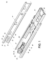
- a self-closing slide rail assembly 10 in an embodiment of the present invention includes a first rail 12, a second rail 14, and a self-closing mechanism 16.
- the self-closing slide rail assembly 10 further includes a third rail 30.
- the second rail 14 can be longitudinally displaced relative to the first rail 12.
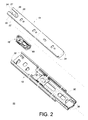
- the second rail 14 includes an end portion 18 corresponding to the self-closing mechanism 16.
- the second rail 14 includes a guide portion 20, a stop portion 22 close to the guide portion 20, and a hook portion 24 close to the stop portion 22.
- the guide portion 20, the stop portion 22, and the hook portion 24 are adjacent to the end portion 18 of the second rail 14.
- the guide portion 20 has a curved guide surface but is not so limited.
- a first positioning groove 26 is defined between the guide portion 20 and the stop portion 22, and a second positioning groove 28 is defined between the stop portion 22 and the hook portion 24.
- the hook portion 24 has an inclined side 27.
- the third rail 30 serves to extend the distance for which the second rail 14 can slide relative to the first rail 12. More specifically, each of the first rail 12, the second rail 14, and the third rail 30 includes a pair of walls 32, 34, 36.
- the walls 36 of the third rail 30 correspond to and are mounted in the walls 32 of the first rail 12 respectively.
- the walls 34 of the second rail 14 correspond to and are mounted in the walls 36 of the third rail 30 respectively. Both the second rail 14 and the third rail 30 are therefore longitudinally displaceable relative to the first rail 12.
- the self-closing mechanism 16 is mounted on the first rail 12.
- the self-closing mechanism 16 can be mounted on the first rail 12 at a position adjacent to an end portion 38 of the first rail 12 by threaded connection, riveting, soldering, adhesive connection, or projection-recess engagement, without limitation.
- the self-closing mechanism 16 has an end portion provided with at least one cushioning arm 68.
- the cushioning arms 68 are configured for pressing against and thereby cushioning the third rail 30 when the third rail 30 is retracted relative to the first rail 12 toward a retracted position.
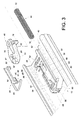
- the self-closing mechanism 16 includes a housing 40, an elastic member 44, and a movable member 46.
- the housing 40 is mounted on the first rail 12 and is adjacent to the end portion 38 of the first rail 12.
- the housing 40 includes a longitudinal portion 50, an accommodation space 52, a first transverse portion 54, a second transverse portion 56, a first edge 58, a second edge 60, and a longitudinal wall 62.
- the accommodation space 52 is in the longitudinal portion 50.
- the first transverse portion 54 is transversely connected to the longitudinal portion 50.
- the second transverse portion 56 corresponds in position to the first transverse portion 54 and is transversely connected to the longitudinal portion 50.
- first edge 58 and the second edge 60 form an included angle therebetween, the first edge 58 is substantially parallel to the longitudinal portion 50, and the second edge 60 deflects from the first edge 58.
- the second transverse portion 56 has a curved surface 64 corresponding in position to the second edge 60.
- the longitudinal wall 62 has a portion connected to the longitudinal portion 50 and is substantially parallel to the longitudinal portion 50 such that a space 66 is formed between the longitudinal wall 62 and the longitudinal portion 50.
- the first edge 58 is located on the longitudinal wall 62.
- the housing 40 of the self-closing mechanism 16 includes an engaging portion 42 having an engaging surface.
- the engaging portion 42 is adjacent to the second edge 60 and is defined between the longitudinal wall 62 and the second transverse portion 56. In one preferred embodiment, the engaging portion 42 is located between the wall body of the longitudinal wall 62, the wall body of the longitudinal portion 50, and the wall body of the second transverse portion 56.
- the elastic member 44 is in the accommodation space 52 of the longitudinal portion 50.
- the elastic member 44 has a first end 70 and a second end 72 opposite the first end 70. The first end 70 corresponds to and presses against an inner wall of the accommodation space 52 of the longitudinal portion 50.
- the movable member 46 corresponds to and is movably connected to the housing 40.
- the movable member 46 includes a first side 74 and a second side 76 opposite the first side 74.
- the first side 74 includes a first projection 78 and a second projection 80.
- the first projection 78 has a surface 82 corresponding to, and configured for pressing against, the second end 72 of the elastic member 44.
- the second side 76 includes an actuating portion 47.
- the actuating portion 47 is integrally connected to the second side 76 of the movable member 46, but the present invention is not limited to this configuration.
- the second projection 80 corresponds to the first transverse portion 54 of the housing 40 and, when the elastic member 44 is in an elastic energy releasing state, is directly or indirectly pressed against a portion of the housing 40 that is adjacent to the first transverse portion 54.
- the self-closing slide rail assembly 10 further includes an auxiliary member 48, through which the second projection 80 is pressed indirectly against a portion of the housing 40 that is adjacent to the first transverse portion 54 in order to keep the elastic member 44 from springing out of the accommodation space 52 of the housing 40.
- the second projection 80 of the movable member 46 corresponds in shape to the engaging portion 42.
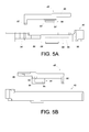
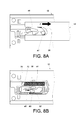
- FIG. 5A is a bottom view of the housing 40 and the auxiliary member 48
- FIG. 5B is a top view of the housing 40 and the auxiliary member 48.
- the first transverse portion 54 and the second transverse portion 56 are connected by a longitudinal wall portion 84.
- the longitudinal wall portion 84 includes a channel 86 in which a groove 88 is formed.
- the longitudinal wall portion 84 includes another channel 89.
- the auxiliary member 48 has a first vertical wall 90, a second vertical wall 92 opposite the first vertical wall 90, and a sliding portion 94 corresponding to the channel 86 of the longitudinal wall portion 84.
- the sliding portion 94 has a first portion 91 and a second portion 93 opposite the first portion 91.
- the first portion 91 has a recess 95.
- the second portion 93 has a rib 97 corresponding to the groove 88 of the channel 86. Thanks to the rib 97, the sliding portion 94 can be displaced stably in the channel 86 of the longitudinal wall portion 84.
- the auxiliary member 48 further includes a sliding block 87 and a lateral extension portion 85.
- the sliding block 87 corresponds to the other channel 89 of the longitudinal wall portion 84
- the lateral extension portion 85 corresponds to the movable member 46 or the actuating portion 47 so as to ensure that the auxiliary member 48 can be driven by the movable member 46 when the movable member 46 is moved and that the auxiliary member 48 will not fall off from the movable member 46.
- the sliding portion 94 of the auxiliary member 48 is mounted in the channel 86 of the longitudinal wall portion 84 of the self-closing mechanism 16.
- the channel 86 of the longitudinal wall portion 84 is filled with a cushioning medium 98 for cushioning the sliding portion 94 of the auxiliary member 48 when the sliding portion 94 is moving in the channel 86.
- the cushioning medium 98 in the channel 86 is attached to the entire sliding portion 94 of the auxiliary member 48 (including the recess 95 and the rib 97).
- the cushioning medium 98 When the auxiliary member 48 is driven toward a retracted position by the second projection 80 of the movable member 46, the cushioning medium 98 not only reduces the speed at which the sliding portion 94 of the auxiliary member 48 moves in the channel 86, but also prevents noise which may otherwise be caused by collision between an end portion of the sliding portion 94 of the auxiliary member 48 and an inner wall of the channel 86. Thus, the cushioning medium 98 provides both cushioning and muffling effects.
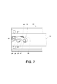
- FIG. 4 Please refer to FIG. 4 in conjunction with FIG. 7 .
- the second projection 80 of the movable member 46 is close to an end portion of the first edge 58.
- the second rail 14 of the self-closing slide rail assembly 10 is in a retracted position with respect to the first rail 12.
- the second projection 80 of the movable member 46 lies between the first vertical wall 90 and the second vertical wall 92 of the auxiliary member 48.
- the second projection 80 of the movable member 46 is pressed against the first transverse portion 54 of the housing 40 indirectly (i.e., via the first vertical wall 90 of the auxiliary member 48) and is adjacent to an end portion of the first edge 58 of the housing 40.
- the first projection 78 of the movable member 46 is pressed against the second end 72 of the elastic member 44.
- FIG. 8 ⁇ FIG. 10 schematically show how the second rail 14 of the self-closing slide rail assembly 10 is displaced relative to the first rail 12 from the retracted position toward an extended position.
- the actuating portion 47 of the movable member 46 is engaged in the first positioning groove 26 of the second rail 14.
- the second rail 14 is longitudinally displaced relative to the first rail 12 toward the extended position by an external force F such that the second projection 80 of the movable member 46 is displaced along the first edge 58.
- the second projection 80 of the movable member 46 is pressed against the second vertical wall 92 of the auxiliary member 48 while the first projection 78 of the movable member 46 is pressed against the second end 72 of the elastic member 44.
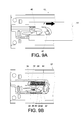
- the second projection 80 of the movable member 46 is moved to the bend between the first edge 58 and the second edge 60. Now that the second projection 80 of the movable member 46 is still pressed against the second vertical wall 92 of the auxiliary member 48, the sliding portion 94 of the auxiliary member 48 is moved together with the movable member 46 along the channel 86 until the position shown in FIG. 9B is reached. In the process, the first projection 78 of the movable member 46 stays pressed against the second end 72 of the elastic member 44.
- the second projection 80 of the movable member 46 is moved from the first edge 58 to the second edge 60 and becomes engaged with the engaging portion 42.
- the movable member 46 is engaged with the engaging portion 42 when moved to the second edge 60.
- the second projection 80 of the movable member 46 is guided by the curved surface 64 of the second transverse portion 56 before engaging with the engaging portion 42.
- the elastic member 44 is in a compressed state and stores elastic energy.
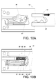
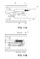
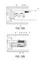
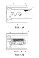
- FIG. 11 ⁇ FIG. 13 schematically show how the second rail 14 of the self-closing slide rail assembly 10 is displaced relative to the first rail 12 from the extended position to the retracted position.
- the guide portion 20 at the end portion 18 of the second rail 14 corresponds to the actuating portion 47 of the movable member 46, and the second projection 80 of the movable member 46 is within the engaging portion 42 of the second edge 60.
- the second projection 80 of the movable member 46 is moved along the curved surface 64 of the second transverse portion 56 and thus leaves the engaging portion 42 of the second edge 60. Consequently, the elastic member 44 of the self-closing mechanism 16 releases the elastic energy F2, which drives the second projection 80 of the movable member 46 from the second edge 60 to the first edge 58, and thanks to the actuating portion 47 of the movable member 46, the second rail 14 is automatically pushed toward the retracted position.
- the auxiliary member 48 is driven to the retracted position along with the movable member 46, and the second rail 14 is driven to the retracted position by the movable member 46 and reenters the retracted state, in which the second projection 80 of the movable member 46 is pressed against the portion of the housing 40 that is adjacent to the first transverse portion 54 in an indirect manner (i.e., via the first vertical wall 90 of the auxiliary member 48).
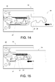
- FIG. 14 ⁇ FIG. 19 show how the self-closing mechanism 16 is released from a failure state by means of the second positioning groove 28 of the second rail 14 so that the self-closing slide rail assembly 10 can resume normal operation.
- the first step of failure elimination is to apply an external force F3 which displaces the second rail 14 relative to the first rail 12 toward the retracted position.
- the goal is to press the actuating portion 47 of the movable member 46 with the inclined side 27 of the hook portion 24 of the second rail 14.
Landscapes
- Engineering & Computer Science (AREA)
- Mechanical Engineering (AREA)
- Drawers Of Furniture (AREA)
Priority Applications (1)
| Application Number | Priority Date | Filing Date | Title |
|---|---|---|---|
| EP14173635.5A EP2959801B1 (de) | 2014-06-24 | 2014-06-24 | Selbstschließende Schienenanordnung und selbstschließender Mechanismus dafür |
Applications Claiming Priority (1)
| Application Number | Priority Date | Filing Date | Title |
|---|---|---|---|
| EP14173635.5A EP2959801B1 (de) | 2014-06-24 | 2014-06-24 | Selbstschließende Schienenanordnung und selbstschließender Mechanismus dafür |
Publications (2)
| Publication Number | Publication Date |
|---|---|
| EP2959801A1 true EP2959801A1 (de) | 2015-12-30 |
| EP2959801B1 EP2959801B1 (de) | 2018-02-28 |
Family
ID=50980193
Family Applications (1)
| Application Number | Title | Priority Date | Filing Date |
|---|---|---|---|
| EP14173635.5A Active EP2959801B1 (de) | 2014-06-24 | 2014-06-24 | Selbstschließende Schienenanordnung und selbstschließender Mechanismus dafür |
Country Status (1)
| Country | Link |
|---|---|
| EP (1) | EP2959801B1 (de) |
Cited By (2)
| Publication number | Priority date | Publication date | Assignee | Title |
|---|---|---|---|---|
| CN106969575A (zh) * | 2017-03-22 | 2017-07-21 | 青岛海尔股份有限公司 | 冷藏冷冻装置及其抽屉组件 |
| US10966547B2 (en) | 2015-11-25 | 2021-04-06 | Aerofoil Energy Limited | Air guiding strip for refrigerators |
Citations (8)
| Publication number | Priority date | Publication date | Assignee | Title |
|---|---|---|---|---|
| DE20308217U1 (de) * | 2003-05-22 | 2003-07-31 | Hettich-Heinze GmbH & Co. KG, 32139 Spenge | Dämpfungs- und Einzugsvorrichtung |
| DE20315265U1 (de) * | 2003-05-15 | 2003-12-11 | King Slide Works Co., Ltd., Lu-Chu Hsiang | Automatische Rückführvorrichtung für eine Schienenvorrichtung |
| US6712435B2 (en) | 2000-05-01 | 2004-03-30 | Accuride International, Inc. | Self-closing slide |
| US20040183411A1 (en) * | 2003-03-20 | 2004-09-23 | Boks Michael J. | Self-closing drawer slide |
| US6971729B1 (en) | 2000-05-01 | 2005-12-06 | Accuride International, Inc. | Self-closing slide |
| US20060082266A1 (en) | 2000-05-01 | 2006-04-20 | Le Hai D | Self-moving slides and self-moving mechanisms |
| DE202009004953U1 (de) * | 2009-06-26 | 2010-11-25 | Paul Hettich Gmbh & Co. Kg | Selbsteinzugsvorrichtung und Auszugsführung |
| US7878606B2 (en) | 2007-02-17 | 2011-02-01 | King Slide Works Co., Ltd. | Slide assembly having an automatic retractable device |
-
2014
- 2014-06-24 EP EP14173635.5A patent/EP2959801B1/de active Active
Patent Citations (9)
| Publication number | Priority date | Publication date | Assignee | Title |
|---|---|---|---|---|
| US6712435B2 (en) | 2000-05-01 | 2004-03-30 | Accuride International, Inc. | Self-closing slide |
| US6733097B2 (en) | 2000-05-01 | 2004-05-11 | Accuride International, Inc. | Self-closing slide and mechanism for a self-closing slide |
| US6971729B1 (en) | 2000-05-01 | 2005-12-06 | Accuride International, Inc. | Self-closing slide |
| US20060082266A1 (en) | 2000-05-01 | 2006-04-20 | Le Hai D | Self-moving slides and self-moving mechanisms |
| US20040183411A1 (en) * | 2003-03-20 | 2004-09-23 | Boks Michael J. | Self-closing drawer slide |
| DE20315265U1 (de) * | 2003-05-15 | 2003-12-11 | King Slide Works Co., Ltd., Lu-Chu Hsiang | Automatische Rückführvorrichtung für eine Schienenvorrichtung |
| DE20308217U1 (de) * | 2003-05-22 | 2003-07-31 | Hettich-Heinze GmbH & Co. KG, 32139 Spenge | Dämpfungs- und Einzugsvorrichtung |
| US7878606B2 (en) | 2007-02-17 | 2011-02-01 | King Slide Works Co., Ltd. | Slide assembly having an automatic retractable device |
| DE202009004953U1 (de) * | 2009-06-26 | 2010-11-25 | Paul Hettich Gmbh & Co. Kg | Selbsteinzugsvorrichtung und Auszugsführung |
Cited By (4)
| Publication number | Priority date | Publication date | Assignee | Title |
|---|---|---|---|---|
| US10966547B2 (en) | 2015-11-25 | 2021-04-06 | Aerofoil Energy Limited | Air guiding strip for refrigerators |
| US12059083B2 (en) | 2015-11-25 | 2024-08-13 | Aerofoil Energy Limited | Air guiding strip for refrigerators |
| CN106969575A (zh) * | 2017-03-22 | 2017-07-21 | 青岛海尔股份有限公司 | 冷藏冷冻装置及其抽屉组件 |
| CN106969575B (zh) * | 2017-03-22 | 2019-11-05 | 青岛海尔股份有限公司 | 冷藏冷冻装置及其抽屉组件 |
Also Published As
| Publication number | Publication date |
|---|---|
| EP2959801B1 (de) | 2018-02-28 |
Similar Documents
| Publication | Publication Date | Title |
|---|---|---|
| US9642460B2 (en) | Self-closing slide rail assembly and self-closing mechanism thereof | |
| US9364089B1 (en) | Self-closing slide rail assembly with deceleration mechanism | |
| US8079653B2 (en) | Sliding track assembly | |
| TWI437967B (zh) | 特別用於活動傢俱件之自行關閉裝置 | |
| EP3387952B1 (de) | Gleitschienenanordnung | |
| EP3387950A1 (de) | Gleitschienenanordnung | |
| TWI440440B (zh) | 抽屜用或家具件之可動件用之自動關閉裝置 | |
| US20110043087A1 (en) | Slide rail buffering structure | |
| CN102573567B (zh) | 自动拉入装置和拉出导向装置 | |
| JP6757361B2 (ja) | スライドレールアセンブリ及びその駆動機構 | |
| EP3387949A1 (de) | Gleitschienenanordnung | |
| EP3289923B1 (de) | Einzugsmechanismus für ein bewegbares möbelteil | |
| US20080296340A1 (en) | Dual-use nail magazine for U-shaped nail and T-shape nail | |
| JP6732937B2 (ja) | 家具用駆動装置 | |
| EP2959801B1 (de) | Selbstschließende Schienenanordnung und selbstschließender Mechanismus dafür | |
| EP3025615B1 (de) | Selbstschließende Schienenanordnung mit Bremsmechanismus | |
| JP3193308U (ja) | セルフクロージング装置及びそれを用いたスライドレールキット | |
| CN105433615B (zh) | 具有减速机构的自闭合滑轨总成及自闭合机构 | |
| US10667607B2 (en) | Retracting mechanism for movable furniture parts | |
| CN105011597B (zh) | 自闭合滑轨总成及其自闭合机构 | |
| EP3403530B1 (de) | Fahrmechanismus, schutzvorrichtung und kontrollverfahren für möbel | |
| JP3196135U (ja) | セルフクロージングスライドレールキット | |
| TWI565440B (zh) | 自閉合滑軌總成及其自閉合機構 | |
| EP2708156B1 (de) | Selbstöffnende und selbstschließende Führungseinrichtung | |
| JP5909409B2 (ja) | 位置調整装置 |
Legal Events
| Date | Code | Title | Description |
|---|---|---|---|
| PUAI | Public reference made under article 153(3) epc to a published international application that has entered the european phase |
Free format text: ORIGINAL CODE: 0009012 |
|
| 17P | Request for examination filed |
Effective date: 20151028 |
|
| AK | Designated contracting states |
Kind code of ref document: A1 Designated state(s): AL AT BE BG CH CY CZ DE DK EE ES FI FR GB GR HR HU IE IS IT LI LT LU LV MC MK MT NL NO PL PT RO RS SE SI SK SM TR |
|
| AX | Request for extension of the european patent |
Extension state: BA ME |
|
| REG | Reference to a national code |
Ref country code: DE Ref legal event code: R079 Ref document number: 602014021529 Country of ref document: DE Free format text: PREVIOUS MAIN CLASS: A47B0088040000 Ipc: A47B0088467000 |
|
| RIC1 | Information provided on ipc code assigned before grant |
Ipc: A47B 88/467 20170101AFI20170426BHEP Ipc: E05F 5/02 20060101ALI20170426BHEP |
|
| GRAP | Despatch of communication of intention to grant a patent |
Free format text: ORIGINAL CODE: EPIDOSNIGR1 |
|
| INTG | Intention to grant announced |
Effective date: 20170920 |
|
| GRAS | Grant fee paid |
Free format text: ORIGINAL CODE: EPIDOSNIGR3 |
|
| GRAA | (expected) grant |
Free format text: ORIGINAL CODE: 0009210 |
|
| AK | Designated contracting states |
Kind code of ref document: B1 Designated state(s): AL AT BE BG CH CY CZ DE DK EE ES FI FR GB GR HR HU IE IS IT LI LT LU LV MC MK MT NL NO PL PT RO RS SE SI SK SM TR |
|
| REG | Reference to a national code |
Ref country code: GB Ref legal event code: FG4D Ref country code: CH Ref legal event code: EP |
|
| REG | Reference to a national code |
Ref country code: AT Ref legal event code: REF Ref document number: 973191 Country of ref document: AT Kind code of ref document: T Effective date: 20180315 |
|
| REG | Reference to a national code |
Ref country code: IE Ref legal event code: FG4D |
|
| REG | Reference to a national code |
Ref country code: DE Ref legal event code: R096 Ref document number: 602014021529 Country of ref document: DE |
|
| REG | Reference to a national code |
Ref country code: NL Ref legal event code: MP Effective date: 20180228 |
|
| REG | Reference to a national code |
Ref country code: LT Ref legal event code: MG4D |
|
| REG | Reference to a national code |
Ref country code: AT Ref legal event code: MK05 Ref document number: 973191 Country of ref document: AT Kind code of ref document: T Effective date: 20180228 |
|
| PG25 | Lapsed in a contracting state [announced via postgrant information from national office to epo] |
Ref country code: ES Free format text: LAPSE BECAUSE OF FAILURE TO SUBMIT A TRANSLATION OF THE DESCRIPTION OR TO PAY THE FEE WITHIN THE PRESCRIBED TIME-LIMIT Effective date: 20180228 Ref country code: CY Free format text: LAPSE BECAUSE OF FAILURE TO SUBMIT A TRANSLATION OF THE DESCRIPTION OR TO PAY THE FEE WITHIN THE PRESCRIBED TIME-LIMIT Effective date: 20180228 Ref country code: NL Free format text: LAPSE BECAUSE OF FAILURE TO SUBMIT A TRANSLATION OF THE DESCRIPTION OR TO PAY THE FEE WITHIN THE PRESCRIBED TIME-LIMIT Effective date: 20180228 Ref country code: HR Free format text: LAPSE BECAUSE OF FAILURE TO SUBMIT A TRANSLATION OF THE DESCRIPTION OR TO PAY THE FEE WITHIN THE PRESCRIBED TIME-LIMIT Effective date: 20180228 Ref country code: LT Free format text: LAPSE BECAUSE OF FAILURE TO SUBMIT A TRANSLATION OF THE DESCRIPTION OR TO PAY THE FEE WITHIN THE PRESCRIBED TIME-LIMIT Effective date: 20180228 Ref country code: NO Free format text: LAPSE BECAUSE OF FAILURE TO SUBMIT A TRANSLATION OF THE DESCRIPTION OR TO PAY THE FEE WITHIN THE PRESCRIBED TIME-LIMIT Effective date: 20180528 Ref country code: FI Free format text: LAPSE BECAUSE OF FAILURE TO SUBMIT A TRANSLATION OF THE DESCRIPTION OR TO PAY THE FEE WITHIN THE PRESCRIBED TIME-LIMIT Effective date: 20180228 |
|
| PG25 | Lapsed in a contracting state [announced via postgrant information from national office to epo] |
Ref country code: BG Free format text: LAPSE BECAUSE OF FAILURE TO SUBMIT A TRANSLATION OF THE DESCRIPTION OR TO PAY THE FEE WITHIN THE PRESCRIBED TIME-LIMIT Effective date: 20180528 Ref country code: LV Free format text: LAPSE BECAUSE OF FAILURE TO SUBMIT A TRANSLATION OF THE DESCRIPTION OR TO PAY THE FEE WITHIN THE PRESCRIBED TIME-LIMIT Effective date: 20180228 Ref country code: AT Free format text: LAPSE BECAUSE OF FAILURE TO SUBMIT A TRANSLATION OF THE DESCRIPTION OR TO PAY THE FEE WITHIN THE PRESCRIBED TIME-LIMIT Effective date: 20180228 Ref country code: RS Free format text: LAPSE BECAUSE OF FAILURE TO SUBMIT A TRANSLATION OF THE DESCRIPTION OR TO PAY THE FEE WITHIN THE PRESCRIBED TIME-LIMIT Effective date: 20180228 Ref country code: SE Free format text: LAPSE BECAUSE OF FAILURE TO SUBMIT A TRANSLATION OF THE DESCRIPTION OR TO PAY THE FEE WITHIN THE PRESCRIBED TIME-LIMIT Effective date: 20180228 |
|
| PG25 | Lapsed in a contracting state [announced via postgrant information from national office to epo] |
Ref country code: EE Free format text: LAPSE BECAUSE OF FAILURE TO SUBMIT A TRANSLATION OF THE DESCRIPTION OR TO PAY THE FEE WITHIN THE PRESCRIBED TIME-LIMIT Effective date: 20180228 Ref country code: RO Free format text: LAPSE BECAUSE OF FAILURE TO SUBMIT A TRANSLATION OF THE DESCRIPTION OR TO PAY THE FEE WITHIN THE PRESCRIBED TIME-LIMIT Effective date: 20180228 Ref country code: PL Free format text: LAPSE BECAUSE OF FAILURE TO SUBMIT A TRANSLATION OF THE DESCRIPTION OR TO PAY THE FEE WITHIN THE PRESCRIBED TIME-LIMIT Effective date: 20180228 Ref country code: AL Free format text: LAPSE BECAUSE OF FAILURE TO SUBMIT A TRANSLATION OF THE DESCRIPTION OR TO PAY THE FEE WITHIN THE PRESCRIBED TIME-LIMIT Effective date: 20180228 Ref country code: IT Free format text: LAPSE BECAUSE OF FAILURE TO SUBMIT A TRANSLATION OF THE DESCRIPTION OR TO PAY THE FEE WITHIN THE PRESCRIBED TIME-LIMIT Effective date: 20180228 |
|
| REG | Reference to a national code |
Ref country code: DE Ref legal event code: R097 Ref document number: 602014021529 Country of ref document: DE |
|
| PG25 | Lapsed in a contracting state [announced via postgrant information from national office to epo] |
Ref country code: DK Free format text: LAPSE BECAUSE OF FAILURE TO SUBMIT A TRANSLATION OF THE DESCRIPTION OR TO PAY THE FEE WITHIN THE PRESCRIBED TIME-LIMIT Effective date: 20180228 Ref country code: SM Free format text: LAPSE BECAUSE OF FAILURE TO SUBMIT A TRANSLATION OF THE DESCRIPTION OR TO PAY THE FEE WITHIN THE PRESCRIBED TIME-LIMIT Effective date: 20180228 Ref country code: SK Free format text: LAPSE BECAUSE OF FAILURE TO SUBMIT A TRANSLATION OF THE DESCRIPTION OR TO PAY THE FEE WITHIN THE PRESCRIBED TIME-LIMIT Effective date: 20180228 Ref country code: CZ Free format text: LAPSE BECAUSE OF FAILURE TO SUBMIT A TRANSLATION OF THE DESCRIPTION OR TO PAY THE FEE WITHIN THE PRESCRIBED TIME-LIMIT Effective date: 20180228 |
|
| PLBE | No opposition filed within time limit |
Free format text: ORIGINAL CODE: 0009261 |
|
| STAA | Information on the status of an ep patent application or granted ep patent |
Free format text: STATUS: NO OPPOSITION FILED WITHIN TIME LIMIT |
|
| REG | Reference to a national code |
Ref country code: CH Ref legal event code: PL |
|
| 26N | No opposition filed |
Effective date: 20181129 |
|
| PG25 | Lapsed in a contracting state [announced via postgrant information from national office to epo] |
Ref country code: SI Free format text: LAPSE BECAUSE OF FAILURE TO SUBMIT A TRANSLATION OF THE DESCRIPTION OR TO PAY THE FEE WITHIN THE PRESCRIBED TIME-LIMIT Effective date: 20180228 |
|
| REG | Reference to a national code |
Ref country code: BE Ref legal event code: MM Effective date: 20180630 |
|
| REG | Reference to a national code |
Ref country code: IE Ref legal event code: MM4A |
|
| PG25 | Lapsed in a contracting state [announced via postgrant information from national office to epo] |
Ref country code: LU Free format text: LAPSE BECAUSE OF NON-PAYMENT OF DUE FEES Effective date: 20180624 Ref country code: MC Free format text: LAPSE BECAUSE OF FAILURE TO SUBMIT A TRANSLATION OF THE DESCRIPTION OR TO PAY THE FEE WITHIN THE PRESCRIBED TIME-LIMIT Effective date: 20180228 |
|
| PG25 | Lapsed in a contracting state [announced via postgrant information from national office to epo] |
Ref country code: CH Free format text: LAPSE BECAUSE OF NON-PAYMENT OF DUE FEES Effective date: 20180630 Ref country code: IE Free format text: LAPSE BECAUSE OF NON-PAYMENT OF DUE FEES Effective date: 20180624 Ref country code: LI Free format text: LAPSE BECAUSE OF NON-PAYMENT OF DUE FEES Effective date: 20180630 Ref country code: FR Free format text: LAPSE BECAUSE OF NON-PAYMENT OF DUE FEES Effective date: 20180630 |
|
| PG25 | Lapsed in a contracting state [announced via postgrant information from national office to epo] |
Ref country code: BE Free format text: LAPSE BECAUSE OF NON-PAYMENT OF DUE FEES Effective date: 20180630 |
|
| PG25 | Lapsed in a contracting state [announced via postgrant information from national office to epo] |
Ref country code: MT Free format text: LAPSE BECAUSE OF NON-PAYMENT OF DUE FEES Effective date: 20180624 |
|
| PG25 | Lapsed in a contracting state [announced via postgrant information from national office to epo] |
Ref country code: TR Free format text: LAPSE BECAUSE OF FAILURE TO SUBMIT A TRANSLATION OF THE DESCRIPTION OR TO PAY THE FEE WITHIN THE PRESCRIBED TIME-LIMIT Effective date: 20180228 |
|
| PG25 | Lapsed in a contracting state [announced via postgrant information from national office to epo] |
Ref country code: PT Free format text: LAPSE BECAUSE OF FAILURE TO SUBMIT A TRANSLATION OF THE DESCRIPTION OR TO PAY THE FEE WITHIN THE PRESCRIBED TIME-LIMIT Effective date: 20180228 |
|
| PG25 | Lapsed in a contracting state [announced via postgrant information from national office to epo] |
Ref country code: HU Free format text: LAPSE BECAUSE OF FAILURE TO SUBMIT A TRANSLATION OF THE DESCRIPTION OR TO PAY THE FEE WITHIN THE PRESCRIBED TIME-LIMIT; INVALID AB INITIO Effective date: 20140624 Ref country code: MK Free format text: LAPSE BECAUSE OF NON-PAYMENT OF DUE FEES Effective date: 20180228 Ref country code: GR Free format text: LAPSE BECAUSE OF FAILURE TO SUBMIT A TRANSLATION OF THE DESCRIPTION OR TO PAY THE FEE WITHIN THE PRESCRIBED TIME-LIMIT Effective date: 20180228 |
|
| PG25 | Lapsed in a contracting state [announced via postgrant information from national office to epo] |
Ref country code: IS Free format text: LAPSE BECAUSE OF FAILURE TO SUBMIT A TRANSLATION OF THE DESCRIPTION OR TO PAY THE FEE WITHIN THE PRESCRIBED TIME-LIMIT Effective date: 20180628 |
|
| PGFP | Annual fee paid to national office [announced via postgrant information from national office to epo] |
Ref country code: DE Payment date: 20250410 Year of fee payment: 12 |
|
| PGFP | Annual fee paid to national office [announced via postgrant information from national office to epo] |
Ref country code: GB Payment date: 20250408 Year of fee payment: 12 |