EP2959934A1 - Moyen à libération contrôlée de liquide de transparence, et endoscope et outil chirurgical endoscopique le comprenant - Google Patents
Moyen à libération contrôlée de liquide de transparence, et endoscope et outil chirurgical endoscopique le comprenant Download PDFInfo
- Publication number
- EP2959934A1 EP2959934A1 EP14754235.1A EP14754235A EP2959934A1 EP 2959934 A1 EP2959934 A1 EP 2959934A1 EP 14754235 A EP14754235 A EP 14754235A EP 2959934 A1 EP2959934 A1 EP 2959934A1
- Authority
- EP
- European Patent Office
- Prior art keywords
- optical clearing
- clearing agent
- component
- sustained release
- stick
- Prior art date
- Legal status (The legal status is an assumption and is not a legal conclusion. Google has not performed a legal analysis and makes no representation as to the accuracy of the status listed.)
- Granted
Links
Images




Classifications
-
- A—HUMAN NECESSITIES
- A61—MEDICAL OR VETERINARY SCIENCE; HYGIENE
- A61B—DIAGNOSIS; SURGERY; IDENTIFICATION
- A61B1/00—Instruments for performing medical examinations of the interior of cavities or tubes of the body by visual or photographical inspection, e.g. endoscopes; Illuminating arrangements therefor
- A61B1/012—Instruments for performing medical examinations of the interior of cavities or tubes of the body by visual or photographical inspection, e.g. endoscopes; Illuminating arrangements therefor characterised by internal passages or accessories therefor
- A61B1/015—Control of fluid supply or evacuation
-
- A—HUMAN NECESSITIES
- A61—MEDICAL OR VETERINARY SCIENCE; HYGIENE
- A61B—DIAGNOSIS; SURGERY; IDENTIFICATION
- A61B1/00—Instruments for performing medical examinations of the interior of cavities or tubes of the body by visual or photographical inspection, e.g. endoscopes; Illuminating arrangements therefor
- A61B1/00064—Constructional details of the endoscope body
- A61B1/00071—Insertion part of the endoscope body
- A61B1/0008—Insertion part of the endoscope body characterised by distal tip features
- A61B1/00082—Balloons
-
- A—HUMAN NECESSITIES
- A61—MEDICAL OR VETERINARY SCIENCE; HYGIENE
- A61B—DIAGNOSIS; SURGERY; IDENTIFICATION
- A61B1/00—Instruments for performing medical examinations of the interior of cavities or tubes of the body by visual or photographical inspection, e.g. endoscopes; Illuminating arrangements therefor
- A61B1/00064—Constructional details of the endoscope body
- A61B1/00071—Insertion part of the endoscope body
- A61B1/0008—Insertion part of the endoscope body characterised by distal tip features
- A61B1/00091—Nozzles
-
- A—HUMAN NECESSITIES
- A61—MEDICAL OR VETERINARY SCIENCE; HYGIENE
- A61B—DIAGNOSIS; SURGERY; IDENTIFICATION
- A61B1/00—Instruments for performing medical examinations of the interior of cavities or tubes of the body by visual or photographical inspection, e.g. endoscopes; Illuminating arrangements therefor
- A61B1/00064—Constructional details of the endoscope body
- A61B1/00071—Insertion part of the endoscope body
- A61B1/0008—Insertion part of the endoscope body characterised by distal tip features
- A61B1/00094—Suction openings
-
- A—HUMAN NECESSITIES
- A61—MEDICAL OR VETERINARY SCIENCE; HYGIENE
- A61B—DIAGNOSIS; SURGERY; IDENTIFICATION
- A61B1/00—Instruments for performing medical examinations of the interior of cavities or tubes of the body by visual or photographical inspection, e.g. endoscopes; Illuminating arrangements therefor
- A61B1/12—Instruments for performing medical examinations of the interior of cavities or tubes of the body by visual or photographical inspection, e.g. endoscopes; Illuminating arrangements therefor with cooling or rinsing arrangements
- A61B1/126—Instruments for performing medical examinations of the interior of cavities or tubes of the body by visual or photographical inspection, e.g. endoscopes; Illuminating arrangements therefor with cooling or rinsing arrangements provided with means for cleaning in-use
-
- A—HUMAN NECESSITIES
- A61—MEDICAL OR VETERINARY SCIENCE; HYGIENE
- A61B—DIAGNOSIS; SURGERY; IDENTIFICATION
- A61B1/00—Instruments for performing medical examinations of the interior of cavities or tubes of the body by visual or photographical inspection, e.g. endoscopes; Illuminating arrangements therefor
- A61B1/12—Instruments for performing medical examinations of the interior of cavities or tubes of the body by visual or photographical inspection, e.g. endoscopes; Illuminating arrangements therefor with cooling or rinsing arrangements
- A61B1/128—Instruments for performing medical examinations of the interior of cavities or tubes of the body by visual or photographical inspection, e.g. endoscopes; Illuminating arrangements therefor with cooling or rinsing arrangements provided with means for regulating temperature
-
- A—HUMAN NECESSITIES
- A61—MEDICAL OR VETERINARY SCIENCE; HYGIENE
- A61B—DIAGNOSIS; SURGERY; IDENTIFICATION
- A61B17/00—Surgical instruments, devices or methods
- A61B17/00234—Surgical instruments, devices or methods for minimally invasive surgery
-
- A—HUMAN NECESSITIES
- A61—MEDICAL OR VETERINARY SCIENCE; HYGIENE
- A61M—DEVICES FOR INTRODUCING MEDIA INTO, OR ONTO, THE BODY; DEVICES FOR TRANSDUCING BODY MEDIA OR FOR TAKING MEDIA FROM THE BODY; DEVICES FOR PRODUCING OR ENDING SLEEP OR STUPOR
- A61M25/00—Catheters; Hollow probes
- A61M25/0021—Catheters; Hollow probes characterised by the form of the tubing
- A61M25/0023—Catheters; Hollow probes characterised by the form of the tubing by the form of the lumen, e.g. cross-section, variable diameter
- A61M25/0026—Multi-lumen catheters with stationary elements
-
- A—HUMAN NECESSITIES
- A61—MEDICAL OR VETERINARY SCIENCE; HYGIENE
- A61M—DEVICES FOR INTRODUCING MEDIA INTO, OR ONTO, THE BODY; DEVICES FOR TRANSDUCING BODY MEDIA OR FOR TAKING MEDIA FROM THE BODY; DEVICES FOR PRODUCING OR ENDING SLEEP OR STUPOR
- A61M25/00—Catheters; Hollow probes
- A61M25/10—Balloon catheters
- A61M25/1011—Multiple balloon catheters
-
- A—HUMAN NECESSITIES
- A61—MEDICAL OR VETERINARY SCIENCE; HYGIENE
- A61B—DIAGNOSIS; SURGERY; IDENTIFICATION
- A61B17/00—Surgical instruments, devices or methods
- A61B17/00234—Surgical instruments, devices or methods for minimally invasive surgery
- A61B2017/00238—Type of minimally invasive operation
- A61B2017/00269—Type of minimally invasive operation endoscopic mucosal resection EMR
-
- A—HUMAN NECESSITIES
- A61—MEDICAL OR VETERINARY SCIENCE; HYGIENE
- A61B—DIAGNOSIS; SURGERY; IDENTIFICATION
- A61B17/00—Surgical instruments, devices or methods
- A61B17/22—Implements for squeezing-off ulcers or the like on inner organs of the body; Implements for scraping-out cavities of body organs, e.g. bones; for invasive removal or destruction of calculus using mechanical vibrations; for removing obstructions in blood vessels, not otherwise provided for
- A61B2017/22051—Implements for squeezing-off ulcers or the like on inner organs of the body; Implements for scraping-out cavities of body organs, e.g. bones; for invasive removal or destruction of calculus using mechanical vibrations; for removing obstructions in blood vessels, not otherwise provided for with an inflatable part, e.g. balloon, for positioning, blocking, or immobilisation
- A61B2017/22061—Implements for squeezing-off ulcers or the like on inner organs of the body; Implements for scraping-out cavities of body organs, e.g. bones; for invasive removal or destruction of calculus using mechanical vibrations; for removing obstructions in blood vessels, not otherwise provided for with an inflatable part, e.g. balloon, for positioning, blocking, or immobilisation for spreading elements apart
-
- A—HUMAN NECESSITIES
- A61—MEDICAL OR VETERINARY SCIENCE; HYGIENE
- A61M—DEVICES FOR INTRODUCING MEDIA INTO, OR ONTO, THE BODY; DEVICES FOR TRANSDUCING BODY MEDIA OR FOR TAKING MEDIA FROM THE BODY; DEVICES FOR PRODUCING OR ENDING SLEEP OR STUPOR
- A61M25/00—Catheters; Hollow probes
- A61M25/10—Balloon catheters
- A61M2025/1043—Balloon catheters with special features or adapted for special applications
- A61M2025/105—Balloon catheters with special features or adapted for special applications having a balloon suitable for drug delivery, e.g. by using holes for delivery, drug coating or membranes
-
- A—HUMAN NECESSITIES
- A61—MEDICAL OR VETERINARY SCIENCE; HYGIENE
- A61M—DEVICES FOR INTRODUCING MEDIA INTO, OR ONTO, THE BODY; DEVICES FOR TRANSDUCING BODY MEDIA OR FOR TAKING MEDIA FROM THE BODY; DEVICES FOR PRODUCING OR ENDING SLEEP OR STUPOR
- A61M25/00—Catheters; Hollow probes
- A61M25/10—Balloon catheters
- A61M2025/1043—Balloon catheters with special features or adapted for special applications
- A61M2025/1086—Balloon catheters with special features or adapted for special applications having a special balloon surface topography, e.g. pores, protuberances, spikes or grooves
-
- A—HUMAN NECESSITIES
- A61—MEDICAL OR VETERINARY SCIENCE; HYGIENE
- A61M—DEVICES FOR INTRODUCING MEDIA INTO, OR ONTO, THE BODY; DEVICES FOR TRANSDUCING BODY MEDIA OR FOR TAKING MEDIA FROM THE BODY; DEVICES FOR PRODUCING OR ENDING SLEEP OR STUPOR
- A61M2202/00—Special media to be introduced, removed or treated
- A61M2202/04—Liquids
- A61M2202/0468—Liquids non-physiological
Definitions
- This invention relates to: a means for sustained release of optical clearing agent which is used for giving an optical clearing agent to a diseased region on a luminal wall surface of a living body for example; an endoscope having the same; and an instrument for endoscopic surgery having the same.
- ESD Endoscopic submucosal dissection
- optical clearing agents is an aqueous solution acquired by adding glycerol and surfactant to urea, and this aqueous solution is applied to a living tissue to penetrate into the living tissue and then makes a penetrated region of the living tissue transparent like a jelly. Besides, the region that is made transparent by the optical clearing agent can be returned into its original state in which the penetrated region is uncleared, again, by giving a saline or the like to the penetrated region.
- Optical clearing agents have been conventionally applied mainly through drop or injection, as disclosed in the following Non Patent Literature 1 or 2 for example.
- an optical clearing agent is applied to a diseased region before or after surgery so that vascular visibility is improved.
- optical clearing agent it is characteristic of such an optical clearing agent to take predetermined time to penetrate into a living tissue, so that time lag occurs until an optical clearing effect is obtained.
- the optical clearing agent has to be applied to a target region with the optical clearing agent remaining at the target region, until the enough optical clearing effect is obtained.
- a target region to which an optical clearing agent should be applied does not necessarily exist in the gravity direction in a lumen.
- an optical clearing agent can be made to remain at a target region in a method of applying an optical clearing agent to a target region through injection.
- the range of a region to which the optical clearing agent is applied is extremely localized.
- the it not only is difficult to apply the optical clearing agent to the whole range of the desired region from an injection point but also has a high invasion for living tissue.
- Patent literature 1 offers an agent-applying instrument that is used with the aim of applying an anesthetic to nasal cavity.
- This agent-applying instrument can be used for applying an agent to a wide range of a diseased region with low invasion with the agent kept stably remaining at the diseased region.
- the agent-applying instrument disclosed in Patent literature 1 includes: an elongated stick-shaped base components 51; a gas passage 52 running along the base component; a cylinder-shaped balloon 53 placed on the whole circumference of the outside surface of the base component 51 and communicating with the gas passage 52; and an agent-holding component 54 placed on the outside surface of the balloon 53 and containing an agent that is applied to the body cavity, as shown in Fig. 8 .
- the agent-applying instrument disclosed in Patent literature 1 is configured to apply an anesthetic to a desired region by supplying air to the gas passage 52 with a gas-supplying instrument to inflate the balloon 53 so that the agent-holding component 54 presses on the inside surface of the desired region to come into contact with the desired region.
- Patent Literature 1 Japanese Patent Kokai No. 2008-188212
- optical clearing agents it is characteristic of optical clearing agents to take predetermined time to penetrate into a target region, so that it takes predetermined time to obtain the effect of making the target region transparent from the time the optical clearing agent was applied to the target region.
- Patent literature 1 is aimed at applying an anesthetic to a nasal cavity, so that Patent literature 1 has no concept of shortening necessary time for obtaining the effect of making a living tissue transparent from the time the optical clearing agent is applied to the living tissue.
- the present invention is made in view of such conventional problems.
- the objective of the present invention is to offer: a means for sustained release of optical clearing agent which makes it possible to shorten necessary time for obtaining the effect of making a target region transparent by the optical clearing agent, to the utmost, with a physical burden on a living body and a work burden being reduced, and which makes it possible to stably give the optical clearing agent to a target region existing in the opposite direction to the gravity direction; an endoscope having the same; and an instrument for endoscopic surgery having the same.
- a means for sustained release of optical clearing agent is characterized in that the means includes: a stick-shaped component which includes at least two supplying passages for supplying gas or liquid, the supplying passages being formed on the inside of the stick-shaped component, and which includes apertures of the respective supplying passages, the apertures being formed at positions along the circumference of the lateral surface in the vicinity of the top end of the stick-shaped component respectively; at least two pouch-shaped elastic components which are placed at positions along the circumference of the lateral surface in the vicinity of the top end of the stick-shaped component respectively to cover the apertures of the supplying passages respectively and which can be controlled to inflate or deflate in accordance with an amount of an inflow of or an outflow of the gas or liquid; an optical clearing agent holding component which is fixed on the surface of a first component of the pouch-shaped elastic components, which holds optical clearing agent, and which is pressed to perform sustained release of the optical clearing agent to the outside; and a body-fluid
- the part in the vicinity of the top end of the stick-shaped component which includes at least two pouch-shaped elastic components, is configured to be capable of rotating on an axis of the stick-shaped component.
- the optical clearing agent holding component includes innumerable protuberances which are formed on its surface.
- the means includes a penetration-rate adjusting means which increases a rate at which the optical clearing agent held by the optical clearing agent holding component penetrates into the target object.
- the penetration-rate adjusting means is a temperature adjusting apparatus which heats gas or liquid supplied to the first pouch-shaped elastic component.
- the penetration-rate adjusting means is a penetration-rate accelerating agent which mixes with the optical clearing agent held by the optical clearing agent holding component.
- the stick-shaped component includes a third supplying passage for supplying gas or liquid with an aperture of the third supplying passage formed at a position along the circumference of the lateral surface in the vicinity of the top end of the stick-shaped component, the third supplying passage being formed on the inside of the stick-shaped component; and the means for sustained release of optical clearing agent includes an optical clearing effect-cancelling agent holding component which is fixed on a surface of a third pouch-shaped elastic component, which holds liquid for returning the living tissue made transparent into its original state in which the living tissue is uncleared, and which is pressed to perform sustained release of the liquid for returning the living tissue made transparent into its original uncleared state of the living tissue to the outside, the third pouch-shaped elastic component being placed at a position along the circumference of the lateral surface in the vicinity of the top end of the stick-shaped component to cover the aperture of the third supplying passage while the position of the third pouch-shaped elastic component placed is being different from the
- the stick-shaped component further includes a supplying passage for supplying the optical clearing agent which communicates with the optical clearing agent holding component.
- an endoscope according to the present invention includes one of the above-described means for sustained release of optical clearing agent of the present invention.
- an instrument for endoscopic surgery includes one of the above-described means for sustained release of optical clearing agent of the present invention.
- [O1] According to the present invention, it is possible to obtain a means for sustained release of optical clearing agent, an endoscope having the same, and an instrument for endoscopic surgery having the same: which make it possible to shorten necessary time for obtaining the effect of making an object transparent by an optical clearing agent to the utmost while a physical burden of a living body and a work burden are being reduced; and which make it possible to stably give the optical clearing agent to also a target region that exists against gravity.
- a luminal wall surface of a living body which is a target for sustained release of optical clearing agent is covered in body fluid. Also, there exists much body fluid in the upper layer of the living tissue which has to be made transparent, also on the inside of the luminal wall surface. When much body fluid mixes with an optical clearing agent, the optical clearing agent is diluted, so that the function of the optical clearing agent making a living tissue transparent deteriorates and penetration of the optical clearing agent into the living tissue that is required to become transparent is retarded.
- the body fluid existing on the surface of or on the inside of the luminal wall surface has to be reduced to the utmost so that the optical clearing agent easily penetrates into the living tissue that is required to become transparent.
- a means for sustained release of optical clearing agent includes: a stick-shaped component which includes at least two supplying passages for supplying gas or liquid and apertures of the respective supplying passage, the supplying passage being located on the inside of the stick-shaped component, and the apertures being located at positions along the circumference of the lateral surface in the vicinity of the top end of the stick-shaped component; at least two pouch-shaped elastic components which are placed at positions along the circumference of the lateral surface in the vicinity of the top end of the stick-shaped component respectively to cover the apertures of the supplying passages respectively and which can be controlled to inflate or deflate in accordance with an amount of inflow of or outflow of the gas or liquid; an optical clearing agent holding component which is fixed on the surface of a first component of the pouch-shaped elastic components, which holds an optical clearing agent, and which is pressed to sustainedly release the optical clearing agent to the outside; and a body-fluid absorbing component which is fixed on the surface of a second component
- sustained release of the optical clearing agent to the luminal wall surface can be performed by the optical clearing agent holding component while the body-fluid absorbing component is removing body fluid adhering to the luminal wall surface to reduce an amount of body fluid in a surface layer of the inside of the luminal wall surface to the utmost.
- an amount of body fluid mixing with the optical clearing agent can be reduced to the utmost, so that it is possible to shorten time which the optical clearing agent needs to penetrate into a living tissue that is required to become transparent in the luminal wall surface.
- the body-fluid absorbing component and the optical clearing agent holding component are placed at positions along the circumference of the lateral surface in the vicinity of the top end of the stick-shaped component respectively.
- absorption of body fluid by the body-fluid absorbing component and sustained release of the optical clearing agent by the optical clearing agent holding component can be changed to each other to perform the absorption of body fluid or the sustained release of the optical clearing agent without inserting or pulling the stick-shaped component into or out of the living body, by rotating on the axis of the stick-shaped component the part in the vicinity of the top end of the stick-shaped component on which the body fluid absorbing component and the optical clearing agent holding component are placed, so that a physical burden on the living body and work burden can be reduced to the utmost.
- the optical clearing agent holding component and the body-fluid absorbing component are fixed on the pouch-shaped elastic components respectively.
- the optical clearing agent holding component and the body-fluid absorbing component can be pressed to come into contact with the luminal wall surface of the target region by inflating the pouch-shaped elastic components respectively, so that also a target region existing in the opposite direction to the direction of gravity can be stably applied the optical clearing agent and body fluid can be stably removed from also the target region existing in the opposite direction to the direction of gravity.
- such a constitution as in the means for sustained release of optical clearing agent according to the present invention makes it possible to shorten necessary time for obtaining the optical clearing effect by the optical clearing agent to the utmost with a physical burden on a living body and a work burden reduced; and, in addition, makes it possible to stably gives an optical clearing agent to also a target region for administration of optical clearing agent which exists in the opposite direction to the direction of gravity.
- a part in the vicinity of the top end of the stick-shaped component which is provided with the at least two pouch-shaped elastic components is configured to be capable of being rotated on the axis of the stick-shaped component in a means for sustained release of optical clearing agent according to the present invention
- absorption of body fluid by the body-fluid absorbing component and sustained release of optical clearing agent by the optical clearing agent holding component can be changed to each other to perform absorption of body fluid or sustained release of optical clearing agent without inserting or pulling the stick-shaped component into or out of a living tissue.
- the optical clearing agent holding component includes innumerable protuberances formed on its surface in a means for sustained release of optical clearing agent according to the present invention
- the protuberances press against the surface of a target region for sustained release of optical clearing agent in the case where the optical clearing agent holding component is pressed to the target object, so that the shape of the surface of the target region is deformed into a bumpy shape corresponding to the protuberances of the optical clearing agent holding component.
- the surface area of the target region into which optical clearing agent penetrates remarkably increases.
- the optical clearing agent holding component can be made to enter the target region for sustained release of optical clearing agent all the more inside because the shape of the surface of the target region for sustained release of optical clearing agent is deformed into the bumpy shape by the protuberances of the optical clearing agent holding component, so that the distance between: the optical clearing agent; and the living tissue that is required to be made transparent and that exists on the inside of the target region for sustained release of optical clearing agent can be shortened.
- a means for sustained release of optical clearing agent includes a penetration-rate adjusting means which increases a rate at which the optical clearing agent held by the optical clearing agent holding component penetrates into a target tissue for sustained release of optical clearing agent, it is possible to accelerate dehydration of body fluid from the target tissue.
- the optical clearing agent holding component is configured in such a way that the surface of the optical clearing agent holding component discharges the optical clearing agent to the outside whereas the surface of the optical clearing agent holding component does not allows body fluid passing through the surface, the body fluid from the target region is dehydrated by the optical clearing agent discharged from the surface of the optical clearing agent holding component and, afterward, body fluid flowing from the target region is absorbed by the body-fluid absorbing component.
- the optical clearing agent holding component is made to press again on the target region in which an amount of the body fluid was reduced, to come into contact with the target region.
- the optical clearing agent discharged from the optical clearing agent holding component can easily penetrate into the inside of the target region.
- the penetration-rate adjusting means is composed of a temperature adjusting apparatus which heats gas or liquid that is supplied to the first pouch-shaped elastic component in a means for sustained release of optical clearing agent according to the present invention
- the penetration-rate adjusting means is composed of a temperature adjusting apparatus which heats gas or liquid that is supplied to the first pouch-shaped elastic component in a means for sustained release of optical clearing agent according to the present invention
- the penetration-rate adjusting means is a penetration-rate accelerating agent which mixes with the optical clearing agent held by the optical clearing agent holding component in a means for sustained release of optical clearing agent according to the present invention, it is possible to shorten necessary time for making the living tissue transparent all the more, the living tissue being required to be transparent and existing on the inside of the target region for sustained release of optical clearing agent.
- a means for sustained release of optical clearing agent is configured in such a way that: the stick-shaped component includes a third supplying passage for supplying gas or liquid with an aperture of the third supplying passage located at a position along the circumference of the lateral surface in the vicinity of the top end of the stick-shaped component, the third supplying passage being formed on the inside of the stick-shaped component; a third pouch-shaped elastic component is placed at a position along the circumference of the lateral surface in the vicinity of the top end of the stick-shaped component to cover the aperture of the third supplying passage while the position of the third pouch-shaped elastic component placed is differing from the positions of the first pouch-shaped elastic component and the second pouch-shaped elastic component placed respectively, the third pouch-shaped elastic component being capable of being controlled to inflate or deflate in accordance with an amount of inflow of or outflow of the gas or liquid; and the means for sustained release of optical clearing agent includes an optical clearing effect-cancelling agent holding component which is fixed on the surface of the third pouch-shaped elastic
- Such a constitution not only makes it possible to shorten time which the optical clearing agent needs to penetrate into the living tissue which is required to become transparent and which exists on the inside of a diseased region on the luminal wall surface by sustainedly releasing the optical clearing agent by the optical clearing agent holding component while an amount of body fluid existing on the surface of or in the surface layer on the inside of the diseased region on the luminal wall surface is being reduced to the utmost by the body-fluid absorbing component but also makes it possible to stably apply the optical clearing effect-cancelling agent to also a target region for sustained release existing in the opposite direction to the direction of gravity without inserting and pulling the stick-shaped component into or out of the living body also in a process of unclearing the living tissue having been made transparent, so that it is possible to reduce a physical burden on the living body and a work burden all the more.
- the stick-shaped component further includes an optical clearing agent supplying passage which communicates with the optical clearing agent holding component in a means for sustained release of optical clearing agent according to the present invention, it is possible to control an amount of the optical clearing agent sustainedly released to the target region for sustained release of optical clearing agent into a suitable amount.
- an endoscope and an instrument for endoscopic surgery include one of the above-described means for sustained release of optical clearing agent according to the present invention, it is possible to realize an endoscope and an instrument for endoscopic surgery which have the effects of the above described means for sustained release of optical clearing agent according to the present invention.
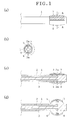
- Fig. 1 is an explanatory view schematically showing a sketchy structure of a means for sustained release of optical clearing agent of the first embodiment according to the present invention
- (a) of Fig. 1 is a side view showing an appearance of a state in which the pouch-shaped elastic components are not inflated
- (b) of Fig. 1 is a cross-sectional view taken along a line A-A in (a) of Fig. 1
- (c) of Fig. 1 is a cross-sectional view taken in the direction parallel to the plane of the paper sheet showing (a) of Fig. 1
- (d) of Fig. 1 is a cross-sectional view showing a state in which the pouch-shaped elastic components are inflated
- FIG. 1 being taken in the direction parallel to the plane of the paper sheet showing (a) of Fig. 1 .
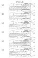
- Fig. 2 is an explanatory view showing an example of a procedure for sustained release of optical clearing agent with the means for sustained release of optical clearing agent of the first embodiment while Fig. 2 is being illustrated as a cross-sectional view taken in the direction parallel to the plane of paper sheet showing (a) of Fig. 2 , (a) of Fig.
- FIG. 2 is a view showing a state in which: the means for sustained release of optical clearing agent is inserted into a lumen with none of the pouch-shaped elastic components inflated; and then position adjustment for the body-fluid absorbing component is performed so that the body-fluid absorbing component faces a target region for sustained release of optical clearing agent
- (b) of Fig. 2 is a view showing a state in which the second pouch-shaped elastic component is inflated from the state shown in (a) of Fig. 2 to press the body-fluid absorbing component to the target region so that the body-fluid absorbing component comes into contact with the target region
- FIG. 2 is a view showing a state in which: the second pouch-shaped elastic component is deflated from the state shown in (b) of Fig. 2 ; and then a part in the vicinity of the top end of the stick-shaped component is rotated on the axis of the stick-shaped component so that the optical clearing agent holding component faces the target region, and (d) of Fig. 2 is a view showing a state in which the first pouch-shaped elastic component is inflated from the state shown in (c) of Fig. 2 to press the optical clearing agent holding component to the target region so that the optical clearing agent holding component comes into contact with the target region.
- a means for sustained release of optical clearing agent of the present embodiment includes a stick-shaped component 1, pouch-shaped elastic components 5 and 6 which are capable of being inflated, an optical clearing agent holding component 7, and a body-fluid absorbing component 8, as shown in (a) to (d) of Fig. 1 .
- the stick-shaped component 1 is made of a flexible material and includes supplying passages 2 and 3 for supplying gas or liquid, the supplying passages 2 and 3 being formed on the inside of the stick-shaped component 1.
- the stick-shaped component 1 includes apertures 2a and 3a of the supplying passages 2 and 3, the apertures 2a and 3a being formed at positions along the circumference of the lateral surface in the vicinity of the top end of the stick-shaped component 1, as shown in (b) of Fig. 1 .
- the supplying passages 2 and 3 connect with a means for supplying and discharging gas or liquid for which a pump or the like is used, and the means for supplying and discharging gas or liquid being not shown in the drawings.
- the pouch-shaped elastic components 5 and 6 are composed of balloons respectively, for example. And, the pouch-shaped elastic components 5 and 6 are placed at positions along the circumference of the lateral surface in the vicinity of the top end of the stick-shaped component 1 respectively to cover the apertures 2a and 3a of the respective supplying passages 2 and 3, as shown in (b) and (c) of Fig. 1 .
- the balloons 5 and 6 are inflated (expand) when gas or liquid is supplied to the insides of the balloons 5 and 6 through the supplying passages 2 and 3 connecting with the means for supplying and discharging gas or liquid which is not shown in the drawings (refer to (d) of Fig. 1 ); and are deflated (contract) when gas or liquid is discharged from the insides of the balloons 5 and 6 through the supplying passages 2 and 3 (refer to (c) of Fig. 1 ).
- the means for sustained release of optical clearing agent is configured to be capable of controlling inflation of and deflation of the balloons in accordance with an amount of inflow of or outflow of gas or liquid.
- the optical clearing agent holding component 7 is fixed on the surface of the balloon 5 and is composed of: a sponge-like component; or a pouch-shaped component having minute holes on the surface of the pouch-shaped component to hold an optical clearing agent inside, for example. And, the optical clearing agent holding component 7 is configured to be pressed to sustainedly release the optical clearing agent to the outside.
- the body-fluid absorbing component 8 is fixed on the surface of the balloon 6 and is composed of: a fiber component like gauze or absorbent cotton which absorbs body fluid from a target region for sustained release of optical clearing agent; or a dehydration sheet which dehydrates the target region for sustained release of optical clearing agent by osmotic pressure, for example.
- the stick-shaped component 1 is configured in such a way that a part in the vicinity of the top end of the stick-shaped component 1 on which the balloons 5 and 6 are placed can be rotated on the axis of the stick-shaped component 1 by a rotary means which is composed of a gear, a rotary shaft, a motor, and so on, the rotary means being not shown in the drawings.
- a reference numeral 20 in Fig. 2 denotes the luminal wall surface
- a reference numeral 20a in Fig. 2 denotes a diseased region on the luminal wall surface (or the target region for sustained release of the optical clearing agent).
- a procedure for performing sustained release of optical clearing agent to a target region for sustained release of optical clearing agent (which is the diseased region 20a on the luminal wall surface 20 in this case) using the means for sustained release of optical clearing agent of the first embodiment having such a configuration is explained using Fig. 2 .
- the surface of the luminal wall surface 20 is covered with body fluid. Also, there exists much body fluid on the upper layer of a living tissue required to become transparent, also on the inside of the luminal wall surface 20. If much body fluid mixes with an optical clearing agent, the optical clearing agent is diluted, so that the function of the optical clearing agent making the living tissue transparent is deteriorated and penetration of the optical clearing agent into the living tissue required to become transparent is retarded.
- the living tissue being required to become transparent, body fluid existing on the surface of and on the inside of the luminal wall surface 20 has to be reduced to the utmost so that the optical clearing agent easily penetrates into the living tissue required to become transparent.
- body fluid on the surface of and on the inside of the diseased region 20a on the luminal wall surface 20 is reduced before sustained release of the optical clearing agent, the diseased region 20 being required to become transparent.
- the means for sustained release of optical clearing agent is inserted into the lumen while the balloons 5 and 6 are not being inflated. And then, the top end which is provided with the balloons 5 and 6 is moved to be located at the position of the diseased region 20a of the luminal wall surface 20. Next, the stick-shaped component 1 is rotated a predetermined amount through the rotary means which is not shown in the drawings so that the body-fluid absorbing component 8 is made to face the diseased region 20a of the luminal wall surface 20 as shown in (a) of Fig. 2 , the diseased region 20a being a target region for sustained release of optical clearing agent.
- gas or liquid
- gas is infused into the balloon 6 through the aperture 3a of the supplying passage 3 connecting with the means for supplying and discharging gas or liquid which is not shown in the drawings, to inflate the balloon 6.
- the balloon 6 presses the body-fluid absorbing component 8 to the diseased region 20a of the luminal wall surface 20 while the balloon 6 is being deformed, as shown in (b) of Fig. 2 .
- the body fluid on the surface of and on the inside of the diseased region 20a of the luminal wall surface 20 is absorbed by the body-fluid absorbing component 8.
- the gas (or liquid) in the balloon 6 is discharged through the aperture 3a of the supplying passage 3 connecting with the means for supplying and discharging gas or liquid, the means for supplying and discharging gas or fluid being not shown in the drawings, so that the balloon 6 is deflated.
- the body-fluid absorbing component 8 moves away from the diseased region 20a of the luminal wall surface 20.
- the part in the vicinity of the top end of the stick-shaped component 1 is rotated 180 degrees by the rotary means which is not shown in the drawings so that the optical clearing agent holding component 7 is made to face the diseased region 20a of the luminal wall surface 20, as shown in (c) of Fig. 2 .
- gas or liquid
- gas is infused into the balloon 5 through the aperture 2a of the supplying passage 2 connecting with a means for supplying and discharging gas or liquid which is not shown in the drawings, to inflate the balloon 5.
- the balloon 5 presses the optical clearing agent holding component 7 to the diseased region 20a of the luminal wall surface 20 while the balloon 5 is being deformed, as shown in (d) of Fig. 2 .
- the optical clearing agent held by the optical clearing agent holding component 7 is sustainedly released to the diseased region 20a of the luminal wall surface 20.
- the optical clearing agent gradually penetrates into the inside of the diseased region 20a of the luminal wall surface 20 by sustained release of optical clearing agent to the diseased region 20a on the luminal wall surface 20, whereas body fluid existing on the inside of the diseased region 20a of the luminal wall surface 20 soaks to enter the optical clearing agent holding component 7.
- the function of the optical clearing agent making living tissue transparent deteriorates when a considerable amount of body fluid enters the optical clearing agent holding component 7 to mix with the optical clearing agent.
- the gas (or liquid) in the balloon 6 is discharged through the aperture 2a of the supplying passage 2 connecting with the means for supplying and discharging gas or liquid which is not shown in the drawings so that the balloon 6 is deflated to separate the optical clearing agent holding component 7 from the diseased region 20a of the luminal wall surface 20.
- the stick-shaped component 1 is rotated 180 degrees by the rotary means which is not shown in the drawings to make the body-fluid absorbing component 8 face the diseased region 20a of the luminal wall surface 20 as shown in (a) of Fig. 2 .
- gas (or liquid) in the balloon 5 is discharged through the aperture 2a of the supplying passage 2 connecting with the means for supplying and discharging gas or liquid which is not shown in the drawings so that the balloon 5 is deflated to move away from the diseased region 20a of the luminal wall surface 20 in which the living tissue has been made transparent.
- the means for sustained release of optical clearing agent is moved to be located at a position far away from the diseased region 20a of the luminal wall surface 20. As a result, it is possible to diagnose or treat the transparent living tissue existing in the diseased region 20a of the luminal wall surface 20.
- the stick-shaped component 1 is pulled out of the living body temporarily. And then, a stick-shaped component 1 including an optical clearing effect-cancelling agent holding component 13 is inserted into the lumen, the optical clearing effect-cancelling agent holding component 13 being fixed on a balloon which is configured in the same manner as the balloons 5 and 6, the optical clearing effect-cancelling agent holding component 13 being composed of a sponge-like component or a pouch-shaped component the surface of which has minute holes for example, and the optical clearing effect-cancelling agent holding component 13 holding saline inside.
- the balloon is inflated to press the optical clearing effect-cancelling agent holding component 13 holding the saline to the diseased region 20a of the luminal wall surface 20 in which the living tissue made transparent exists and to make the optical clearing effect-cancelling agent holding component 13 come into contact with the diseased region 20a of the luminal wall surface 20, with the same procedure as explained above using (c) and (d) of Fig. 2 , and then the saline is sustainedly released.
- the optical clearing agent in the living tissue is exchanged for the saline, with the result that the living tissue having been made transparent is returned into its original state in which the living tissue is uncleared.
- the means of the first embodiment includes: the stick-shaped component 1 which has the two supplying passages 2 and 3 for supplying gas or liquid inside and which has the apertures 2a and 3a of the supplying passage 2 and 3 at the positions along the circumference of the lateral surface in the vicinity of the top end of the stick-shaped component 1; the at least two pouch-shaped elastic components 5 and 6 which are placed at positions along the circumference of the lateral surface in the vicinity of the top end of the stick-shaped component 1 respectively to cover the apertures 2a and 3a of the supplying passages 2 and 3 respectively and which can be controlled to inflate or deflate in accordance with an amount of inflow of or outflow of gas or liquid; the optical clearing agent holding component 7 which is fixed on the surface of the first pouch-shaped elastic component 5, which holds the optical clearing agent, and which is pressed to sustainedly release the optical clearing agent to the outside; and the body-fluid absorbing component 8 which is fixed on the surface of the second pouch-shaped
- the optical clearing agent holding component 7 can sustainedly release the optical clearing agent to the luminal wall surface 20 while an amount of body fluid existing in a surface layer on the inside of the luminal wall surface 20 is being reduced to the utmost by removing body fluid adhering to the surface of the luminal wall surface 20 by the body-fluid absorbing component 8.
- the body-fluid absorbing component 8 and the optical clearing agent holding component 7 are placed at positions along the circumference of the lateral surface in the vicinity of the top end of the stick-shaped component 1, respectively.
- absorption of body fluid by the body-fluid absorbing component 8 and sustained release of the optical clearing agent by the optical clearing agent holding component 7 can be changed to each other to be performed respectively without a process of inserting the stick-shaped component 1 into or pulling the stick-shaped component 1 out of the living body by rotating on the axis of the stick-shaped component 1 the part in the vicinity of the top end of the stick-shaped component 1 on which the body fluid absorbing component 8 and the optical clearing agent holding component 7 are placed, so that it becomes possible to reduce a physical burden on the living tissue and a work burden to the utmost.
- the optical clearing agent holding component 7 and the body-fluid absorbing component 8 are fixed on the first pouch-shaped elastic component 5 and the second pouch-shaped elastic component 6, respectively, and the first pouch-shaped elastic component 5 and the second pouch-shaped elastic component 6 are inflated to be capable of pressing the optical clearing agent holding component 7 and the body-fluid absorbing component 8 to a target region of the luminal wall surface 20 respectively so that the optical clearing agent holding component 7 and the body-fluid absorbing component 8 can come into contact with the target region of the luminal wall surface 20.
- the optical clearing agent can be stably applied to also a target region existing in the opposite direction to the direction of gravity, and, in addition, it is possible to stably remove body fluid.
- the means for sustained release of optical clearing agent of the first embodiment makes it possible to shorten necessary time for obtaining the optical clearing effect by an optical clearing agent to the utmost with a physical burden on a living body and a work burden reduced.
- the means for sustained release of optical clearing agent of the first embodiment makes it possible to stably apply an optical clearing agent to also a target region to be applied the optical clearing agent which exists in the opposite direction to the direction of gravity.
- the part in the vicinity of the top end of the stick-shaped component 1, which is provided with the two pouch-shaped elastic components 5 and 6, is configured to be capable of rotating on the axis of the stick-shaped component 1.
- absorption of body fluid by the body-fluid absorbing component 8 and sustained release of the optical clearing agent by the optical clearing agent holding component 7 can be changed to each to be performed respectively other without inserting or pulling the stick-shaped component 1 into or out of a living body, so that the effect of reducing a physical burden on the living body and a work burden to the utmost can be realized.
- Fig. 3 is an explanatory view showing a means for sustained release of optical clearing agent of the second embodiment according to the present invention
- (a) of Fig. 3 is a partially enlarged cross-sectional view showing the surface shape of the optical clearing agent holding component 7
- (b) of Fig. 3 is a view showing an area which the optical clearing agent holding component 7 for the means for sustained release of optical clearing agent of the second embodiment shown in (a) of Fig. 3 occupies
- (c) of Fig. 3 is a view showing a state in which the optical clearing agent holding component 7 is pressed to a target region for sustained release of optical clearing agent so that the optical clearing agent holding component 7 comes into contact with the target region
- FIG. 3 is a view showing: the shape of the pressed contact surface of the target region for sustained release of optical clearing agent in the range of the area shown in (c) of Fig. 3 ; and a position in the direction in which the optical clearing agent holding component 7 is pressed to come into contact with the target region, when the optical clearing agent holding component 7 is pressed to the target region to come into contact with the target region through the means for sustained release of optical clearing agent of the second embodiment, and (e) of Fig. 3 is a view showing one example for comparison with the optical clearing agent holding component 7 shown in (d) of Fig. 3 and showing: the shape of the pressed contact surface of the target region for sustained release of optical clearing agent in the range of the area shown in (c) of Fig.
- a means for sustained release of optical clearing agent of the present embodiment not only has the constitutions of the means of the first embodiment shown in Fig. 1 but also has a constitution in which innumerable protuberances 7a are formed on the surface of the optical clearing agent holding component 7, as shown in (a) of Fig. 3 .
- a sign P denoting a part that is surrounded by a circle in (b) of Fig. 3 corresponds to a range of the part of the optical clearing agent holding component 7 which is enlarged to be shown in (a) of Fig. 3 .
- the other constitutions of the present embodiment are approximately equal to those of the means for sustained release of optical clearing agent of the first embodiment shown in (a) to (d) of Fig. 1 .
- the optical clearing agent holding component 7 of the comparative example having a smooth surface is pressed to the diseased region 20a of the luminal wall surface 20 to come into contact with the diseased region 20a of the luminal wall surface 20
- the area of the contact surface of the diseased region 20a of the luminal wall surface 20 with the optical clearing agent holding component 7 is limited to the area of a part over which the flat surface of the diseased region 20a of the luminal wall surface 20 comes into contact with the flat surface of the optical clearing agent holding component 7, as shown in (e) of Fig. 3 .
- the surface area of the diseased region into which the optical clearing agent penetrates is also limited.
- optical clearing agent holding component 7 is pressed to the diseased region 20a with the whole of the smooth surface of the optical clearing agent holding component 7, it is difficult to put a position of the optical clearing agent holding component 7 in the direction of the press of the diseased region 20a on the inside of the diseased region 20a of the luminal wall surface 20.
- the optical clearing agent holding component 7 including the innumerable protuberances 7a on its surface as in the means for sustained release of optical clearing agent of the second embodiment is pressed to the diseased region 20a of the luminal wall surface 20 to come into contact with the diseased region 20a of the luminal wall surface 20, the respective protuberances 7a are pressed into the surface of the diseased region 20a of the luminal wall surface 20, to deform the surface of the diseased region 20a into a bumpy surface corresponding to the bums 7a of the optical clearing agent holding component 7, as shown in (d) of Fig. 3 .
- the surface area of the diseased region 20a of the luminal wall surface 20 into which the optical clearing agent penetrates is remarkably increased in the second embodiment to be much larger than that in the comparable example.
- the distance between: the optical clearing agent; and a living tissue existing on the inside of the diseased region 20a of the luminal wall surface 20 and being required to become transparent can be shortened.
- the means for sustained release of optical clearing agent of the second embodiment makes it possible to apply more optical clearing agent to a target region for sustained release of the optical clearing agent; and, in addition, makes it possible to shorten the distance to a living tissue that exists on the inside of the target region for sustained release into which the optical clearing agent penetrates and that is required to become transparent. As a result, it is possible to remarkably shorten necessary time for making the living tissue transparent, the living tissue: existing on the inside of the target region for sustained release of optical clearing agent; and being required to become transparent.
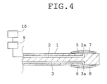
- Fig. 4 is an explanatory view schematically showing a sketchy structure of a means for sustained release of optical clearing agent of a third embodiment according to the present invention.
- a means for sustained release of optical clearing agent of the present embodiment not only has the constitutions of the first embodiment shown in Fig. 1 but also includes a temperature adjusting apparatus 10 which is used as one of penetration-rate adjusting means that increase a penetration rate of an optical clearing agent held by the optical clearing agent holding component 7, as shown in Fig. 4 .
- the numeral reference 9 in Fig. 4 denotes a means for supplying and discharging gas or liquid which is omitted in Fig. 1 and for which a pump is used.
- a means for supplying and discharging gas or liquid which is the same as the means 9 is connected with also the supplying passage 3, but the same means for supplying and discharging gas or liquid as the means 9 is omitted also in Fig. 4 .
- the temperature adjusting apparatus 10 heats gas (or liquid) supplied to the pouch-shaped elastic component 5 to a predetermined temperature. Heat caused by the heating is conveyed through the pouch-shaped elastic component 5 to the optical clearing agent holding component 7, so that a penetration rate of an optical clearing agent held by the optical clearing agent holding means 7 is increased.
- penetration-rate accelerating agent may be mixed with the optical clearing agent held by the optical clearing agent holding component 7.
- the other constitutions of the present embodiment are approximately equal to those of the means for sustained release of optical clearing agent of the first embodiment shown in Fig. 1 .
- gas or liquid which is heated to a predetermined temperature by the temperature adjusting apparatus 10 is supplied into the balloon 5 through the aperture 2a of the supplying passage 2 connecting with the means 9 for supplying and discharging gas or liquid, so that the balloon 5 is inflated and heat of the heated gas or liquid in the balloon 5 heats the optical clearing agent held by the optical clearing agent holding component 7. As a result, a penetration rate of the optical clearing agent is increased.
- the balloon 5 is inflated to press the optical clearing agent holding component 7 to the diseased region 20a of the luminal wall surface 20 so that the optical clearing agent holding component 7 comes into contact with the diseased region 20a of the luminal wall surface 20 as shown in (d) of Fig. 2 , with the optical clearing agent 7 holding the optical clearing agent the penetration rate of which is improved.
- the optical clearing agent the penetration rate of which is increased is sustainedly released from the optical clearing agent holding component 7.
- the optical clearing agent the penetration rate of which is increased accelerates dehydration of body fluid existing on the inside of the diseased region 20a of the luminal wall surface 20. Accordingly, the surface of the optical clearing agent holding component 7 is configured to discharge the optical clearing agent to the outside but not to conduct body fluid.
- body fluid is dehydrated from the inside of the diseased region 20a of the luminal wall surface 20 by the optical clearing agent flowing out through the surface of the optical clearing agent holding component 7, the body fluid flowing out from the inside of the diseased region 20a of the luminal wall surface 20 is absorbed by the body-fluid absorbing component 8 afterward, and then the optical clearing agent holding component 7 is again pressed to the diseased region 20a of the luminal wall surface 20 to come into contact with the diseased region 20a of the luminal wall surface 20 again when the diseased region 20a of the luminal wall surface 20 has a small amount of body fluid.
- the penetration-rate adjusting means is composed of the temperature adjusting apparatus 11 that heats gas or liquid supplied to the pouch-shaped elastic component 5, so that it becomes easy to adjust an extent of shortening of necessary time for making a living tissue transparent, the living tissue being existing on the inside of the diseased region 20a of the luminal wall surface 20 and being required to become transparent.
- a penetration-rate accelerating agent is used as the penetration-rate adjusting means, and the penetration-rate accelerating agent is mixed with the optical clearing agent held by the optical clearing agent holding component 7.
- Fig. 5 is an explanatory view schematically showing a sketchy structure of a means for sustained release of optical clearing agent of the fourth embodiment according to the present invention
- (a) of Fig. 5 is a side view showing an appearance of a state in which the pouch-shaped elastic components are not inflated
- (b) of Fig. 5 is a cross-sectional view taken along a line A'-A' in (a) of Fig. 5
- (c) of Fig. 5 is a cross-sectional view taken in the direction parallel to the plane of the paper sheet showing (a) of Fig. 5 .
- Fig. 5 is an explanatory view schematically showing a sketchy structure of a means for sustained release of optical clearing agent of the fourth embodiment according to the present invention
- (a) of Fig. 5 is a side view showing an appearance of a state in which the pouch-shaped elastic components are not inflated
- (b) of Fig. 5 is a cross-sectional view taken along a line A'-A' in (
- FIG. 6 is an explanatory view showing an example of a procedure for sustained release of optical clearing agent with the means for sustained release of optical clearing agent of the fourth embodiment according to the present invention while Fig. 6 is being illustrated as a cross-sectional view taken in the direction parallel to the plane of paper sheet showing (a) of Fig. 6 , (a) of Fig. 6 is a view showing a state in which: the means for sustained release of optical clearing agent is inserted into a lumen with none of the pouch-shaped elastic components inflated; and then the position adjustment for body-fluid absorbing component is performed so that the body-fluid absorbing component faces a target region for sustained release of optical clearing agent, (b) of Fig.
- FIG. 6 is a view showing a state in which the second pouch-shaped elastic component is inflated from the state shown in (a) of Fig. 6 to press the body-fluid absorbing component to the target region so that the body-fluid absorbing component comes into contact with the target region
- (c) of Fig.6 is a view showing a state in which: the second pouch-shaped elastic component is deflated from the state shown in (b) of Fig. 6 ; and then a part in the vicinity of the top end of the stick-shaped component is rotated on the axis of the stick-shaped component so that the optical clearing agent holding component faces the target region
- FIG. 6 is a view showing a state in which the first pouch-shaped elastic component is inflated from the state shown in (c) of Fig. 6 to press the optical clearing agent holding component to the target region so that the optical clearing agent holding component comes into contact with the target region
- (e) of Fig. 6 is a view showing a state in which: the first pouch-shaped elastic component is deflated from the state shown in (d) of Fig. 6 ; and then the part in the vicinity of the top end of the stick-shaped component is rotated on the axis of the stick-shaped component so that the optical clearing effect-cancelling agent holding component faces the target region
- FIG. 6 is a view showing a state in which the third pouch-shaped elastic component is inflated from the state shown in (e) of Fig. 6 to press the optical clearing effect-cancelling agent holding component to the target region so that the optical clearing effect-cancelling agent holding component comes into contact with the target region.
- a means for sustained release of optical clearing agent of the present embodiment includes not only the components shown in Fig. 1 but also an expandable pouch-shaped elastic component 12 and an optical clearing effect-cancelling agent holding component 13, as shown in (a) to (c) of Fig. 5 .
- the stick-shaped component 1 includes not only the supplying passages 2 and 3 but also a supplying passage 11 for supplying gas or liquid, the supplying passages 2, 3, and 11 being formed on the inside of the stick-shaped component 1.
- the stick-shaped component 1 includes apertures 2a, 3a, and 11a of the supplying passages 2, 3, and 11 which are formed at positions along the circumference of the lateral surface in the vicinity of the top end of the stick-shaped component 1 respectively.
- the supplying passage 11 is connected with the means for supplying and discharging gas or liquid which is not shown in the drawings and for which a pump is used, as well as the supplying passages 2 and 3.
- the pouch-shaped elastic component 12 is composed of a balloon for example and is placed at a position along the circumference of the lateral surface in the vicinity of the top end of the stick-shaped component 1 while the position of the pouch-shaped component 12 placed is being different from the positions of the balloons 5 and 6 placed respectively, and the pouch-shaped elastic component 12 covers the aperture 11 a of the supplying passage 11, as shown in (b) and (c) of Fig. 5 .
- gas or liquid is supplied to the inside of the balloon 12 through the aperture 11 a of the supplying passage 11 to expand (inflate) the balloon 12, the supplying passage 11 being connected with the means for supplying and discharging the gas or the liquid which is not shown in the drawings. And, gas or liquid is discharged from the inside of the balloon 12 through the aperture 11 a of the supplying passage 11 to contract (deflate) the balloon 12.
- the balloon 12 is configured to be capable of being controlled to inflate or deflate in accordance with an amount of inflow of or outflow of gas or liquid.
- the optical clearing effect-cancelling agent holding component 13 holds an optical clearing effect-cancelling agent like a saline inside, the optical clearing effect-cancelling agent being used for retuning a living tissue having been made transparent into its original state in which the living tissue is uncleared. And, the optical clearing effect-cancelling agent holding component 13 is pressed to sustainedly release the optical clearing effect-cancelling agent to the outside.
- the optical clearing effect-cancelling agent holding component is made as: a sponge-like component; or a pouch-shaped component the surface of which is provided with minute holes, and the optical clearing effect-cancelling agent holding component 13 is fixed on the surface of the balloon 12.
- the other constitutions of the present embodiment are approximately equal to those of the means for sustained release of optical clearing agent which is shown in Fig. 1 .
- the means for sustained release of optical clearing agent of the fourth embodiment having such a configuration makes it possible to perform processes: from sustained release of optical clearing agent to the diseased region 20a of the luminal wall surface 20 which is a target region for sustained release of optical clearing agent; to sustained release of optical clearing effect-cancelling agent to the diseased region 20a of the luminal wall surface 20 for returning a living tissue having been made transparent into its original uncleared state of the living tissue, without pulling out the stick-shaped component 1 form the living body.
- the procedure for performing these processes is explained using Fig. 6 .
- the procedure for performing sustained release of an optical clearing agent to the diseased region 20a of the luminal wall surface 20 in the present embodiment is approximately equal to that in the means for sustained release of optical clearing agent of the first embodiment shown in Fig.2 .
- the means for sustained release of optical clearing agent is inserted into a lumen without inflating the balloons 5, 6, and 12. And, the top end including the balloons 5, 6, and 12 is moved to be located at a position of the diseased region 20a of the luminal wall surface 20.
- the stick-shaped component 1 is rotated a predetermined amount by the rotary means which is not shown in the drawings so that the body-fluid absorbing component 8 faces the diseased region 20a of the luminal wall surface 20 which is a target region for sustained release of optical clearing agent, as shown in (a) of Fig. 6 .
- gas or liquid
- inflate balloon 6 gas (or liquid) is supplied to the inside of the balloon 6 through the aperture 3a of the supplying passage 3 connecting with the means for supplying and discharging gas or liquid which is not shown in the drawings, to inflate balloon 6.
- the balloon 6 is deformed to press the body-fluid absorbing component 8 to the diseased region 20a of the luminal wall surface 20 so that the body-fluid absorbing component 8 comes into contact with the diseased region 20a of the luminal wall surface 20, as shown in (b) of Fig. 6 .
- body fluid from the surface of or the inside of the diseased region 20a is absorbed by the body-fluid absorbing component 8.
- the gas (or liquid) in the balloon 6 is discharged through the aperture 3a of the supplying component 3 connecting with the means for supplying and discharging gas or liquid which is not shown in the drawings, to deflate the balloon 6.
- the body-fluid absorbing component 8 is separated from the diseased region 20a of the luminal wall surface 20.
- gas or liquid
- inflate balloon 5 gas (or liquid) is supplied to the inside of the balloon 5 through the aperture 2a of the supplying passage 2a connecting with the means for supplying and discharging gas or liquid which is not shown in the drawings, to inflate balloon 5.
- the balloon 5 is deformed to press the optical clearing agent holding component 7 to the diseased region 20a so that the optical clearing agent holding component 7 comes into contact with the diseased region 20a, as shown in (d) of Fig. 6 .
- optical clearing agent held by the optical clearing agent holding component 7 is sustainedly released to the diseased region 20a of the luminal wall surface 20.
- the gas (or liquid) in the balloon 6 is discharged through the aperture 2a of the supplying passage 2 connecting with the means for supplying and discharging gas or liquid which is not shown in the drawings, to deflate the balloon 6, in the middle of the sustained release of the optical clearing agent.
- the optical clearing agent holding component 7 is separated from the diseased region 20a of the luminal wall surface 20.
- the stick-shaped component 1 is rotated 180 degrees by the rotary means which is not shown in the drawings, so that the body-fluid absorbing component 8 faces the diseased region 20a, as shown in (a) of Fig. 6 .
- the gas (or liquid) in the balloon 5 is discharged through the aperture 2a of the supplying passage 2 connecting with the means for supplying and discharging gas or liquid which is not shown in the drawings, to deflate the balloon 5.
- the balloon 5 is separated from the diseased region 20a of the luminal wall surface 20 in which the living tissue has become transparent.
- the means for sustained release of optical clearing agent is temporarily kept away from the diseased region 20a of the luminal wall surface 20. As a result, it is possible to diagnose or treat the transparent living tissue existing in the diseased region 20a of the luminal wall surface 20.
- the means for sustained release of optical clearing agent is inserted into the lumen while the balloons 5, 6, and 12 are not being inflated, and the top end of the stick-shaped component 1 including the balloons 5, 6, and 12 is moved to be located at the position of the diseased region 20a of the luminal wall surface 20.
- the stick-shaped component 1 is rotated a predetermined amount by the rotary means which is not shown in the drawings, so that the optical clearing effect-cancelling agent holding component 13 is made to face the diseased region 20a of the luminal wall surface 20 which is a target region for sustained release of optical clearing agent and in which the living tissue having been made transparent exists, as shown in (e) of Fig. 6 .
- gas or liquid
- gas is supplied to the inside of the balloon 12 through the aperture 11a of the supplying passage 11 connecting with the means for supplying and discharging gas or liquid which is not shown in the drawings, to inflate the balloon 12.
- the balloon 12 is deformed to press the optical clearing effect-cancelling agent holding component 13 to the transparent diseased region 20a of the luminal wall surface 20 so that the optical clearing effect-cancelling agent holding component 13 comes into contact with the transparent diseased region 20a of the luminal wall surface 20, as shown in (f) of Fig. 6 .
- saline held by the optical clearing effect-cancelling agent holding component 13 is sustainedly released to the diseased region 20a of the luminal wall surface 20, so that the saline is exchanged for the optical clearing agent in the living tissue and then the living tissue having been put transparent is returned into its original state in which the living tissue is uncleared.
- the stick-shaped component 1 includes: the third supplying passage 11 for supplying gas or liquid which is formed on the inside of the stick-shaped component 1; and the aperture 11a of the third supplying passage which is formed at a position along the circumference of the lateral surface in the vicinity of the top end of the stick-shaped component 1, and the means for sustained release of optical clearing agent of the fourth embodiment includes the optical clearing effect-cancelling agent component 13 which is fixed on the surface of the balloon 12, which holds the liquid for returning a living tissue having been made transparent into its original uncleared state, and which is pressed to sustainedly releases the liquid for returning the transparent living tissue into its original uncleared state to the outside, the balloon 12 being placed at the position along the circumference of the lateral surface in the vicinity of the top end of the stick-shaped component to cover the aperture 11 a of the third supplying passage while the position of the balloon 12 (the third pouch-shaped elastic component) placed is being different from the places of the balloon 5 (the first pouch-shaped elastic component
- Fig. 7 is an explanatory view schematically showing a sketchy structure of a means for sustained release of optical clearing agent of the fifth embodiment according to the present invention.
- a means for sustained release of optical clearing agent of the present embodiment not only has the constitutions of the first embodiment shown in Fig. 1 but also has a constitution in which the stick-shaped component 1 further includes a supplying passage 14 for supplying optical clearing agent which connects with the optical clearing agent holding component 7 through a connection part 14a.
- the supplying passage 14 is connected with a means for supplying and discharging an optical clearing agent which is not shown in the drawings and for which a pump or the like is used.
- the other constitutions of the present embodiment are approximately equal to those of the means for sustained release of optical clearing agent of the first embodiment.
- the stick-shaped component 1 has to be inserted into a living body again, after the stick-shaped component 1 is pulled out from the living body temporarily and then the optical clearing agent component 13 is replenished with an optical clearing agent.
- the stick-shaped component 1 further includes the supplying passage 14 for supplying optical clearing agent which connects with the optical clearing agent holding component 7, so that it becomes possible to control an amount of optical clearing agent sustainedly released to a target region into a suitable amount.
- means for sustained release of optical clearing agent according to the present invention have been explained up to now.
- means for sustained release of optical clearing agent according to the present invention are not limited to the constitutions for above-described embodiments, and the characteristic constitutions of the respective embodiments may be optionally combined with one another.
- the pouch-shaped elastic components are not limited to the balloons, and any component expanding into a shape of a pouch and having elasticity may be used as a pouch-shaped elastic component.
- the means for sustained release of optical clearing agent may be configured to be integrated with the top end of an endoscope or may be configured to be integrated with an instrument for endoscopic surgery like a extractor which is used together with an endoscope.
- a means for sustained release of optical clearing agent according to the present invention and an endoscope and an instrument for endoscopic surgery which have the same are useful for every field in which a diseased region existing in the opposite direction to the direction of gravity has to be applied an optical clearing agent while the optical clearing agent is being kept on the diseased region and has to be diagnosed or treated immediately after giving the optical clearing agent to the diseased region.
Landscapes
- Health & Medical Sciences (AREA)
- Life Sciences & Earth Sciences (AREA)
- Surgery (AREA)
- Heart & Thoracic Surgery (AREA)
- Biomedical Technology (AREA)
- Public Health (AREA)
- Engineering & Computer Science (AREA)
- Veterinary Medicine (AREA)
- Animal Behavior & Ethology (AREA)
- General Health & Medical Sciences (AREA)
- Biophysics (AREA)
- Molecular Biology (AREA)
- Medical Informatics (AREA)
- Nuclear Medicine, Radiotherapy & Molecular Imaging (AREA)
- Physics & Mathematics (AREA)
- Optics & Photonics (AREA)
- Pathology (AREA)
- Radiology & Medical Imaging (AREA)
- Pulmonology (AREA)
- Hematology (AREA)
- Anesthesiology (AREA)
- Child & Adolescent Psychology (AREA)
- Medicinal Preparation (AREA)
- Infusion, Injection, And Reservoir Apparatuses (AREA)
- Surgical Instruments (AREA)
- Endoscopes (AREA)
- Media Introduction/Drainage Providing Device (AREA)
Applications Claiming Priority (2)
| Application Number | Priority Date | Filing Date | Title |
|---|---|---|---|
| JP2013032499A JP5984710B2 (ja) | 2013-02-21 | 2013-02-21 | 透明化液徐放手段並びにそれを備えた内視鏡及び内視鏡手術用器具 |
| PCT/JP2014/054058 WO2014129551A1 (fr) | 2013-02-21 | 2014-02-20 | Moyen à libération contrôlée de liquide de transparence, et endoscope et outil chirurgical endoscopique le comprenant |
Publications (3)
| Publication Number | Publication Date |
|---|---|
| EP2959934A1 true EP2959934A1 (fr) | 2015-12-30 |
| EP2959934A4 EP2959934A4 (fr) | 2016-10-19 |
| EP2959934B1 EP2959934B1 (fr) | 2017-10-04 |
Family
ID=51391333
Family Applications (1)
| Application Number | Title | Priority Date | Filing Date |
|---|---|---|---|
| EP14754235.1A Not-in-force EP2959934B1 (fr) | 2013-02-21 | 2014-02-20 | Moyen à libération contrôlée de liquide de transparence, et endoscope et outil chirurgical endoscopique le comprenant |
Country Status (4)
| Country | Link |
|---|---|
| US (1) | US10136802B2 (fr) |
| EP (1) | EP2959934B1 (fr) |
| JP (1) | JP5984710B2 (fr) |
| WO (1) | WO2014129551A1 (fr) |
Cited By (1)
| Publication number | Priority date | Publication date | Assignee | Title |
|---|---|---|---|---|
| US12133628B2 (en) | 2018-07-27 | 2024-11-05 | Olympus Corporation | Medical device |
Families Citing this family (7)
| Publication number | Priority date | Publication date | Assignee | Title |
|---|---|---|---|---|
| WO2016042641A1 (fr) * | 2014-09-18 | 2016-03-24 | オリンパス株式会社 | Système d'administration pour médicament liquide perméable, et procédé d'administration pour médicament liquide perméable |
| WO2016103425A1 (fr) * | 2014-12-25 | 2016-06-30 | オリンパス株式会社 | Dispositif d'observation de corps vivant et procédé d'observation de corps vivant |
| RU2638642C2 (ru) * | 2015-06-11 | 2017-12-14 | Олимпус Корпорейшн | Способ наблюдения жировой ткани |
| EP3340945B1 (fr) * | 2015-08-26 | 2023-01-18 | Edwards Lifesciences Corporation | Déploiement commandé de ballonnet |
| US10834759B2 (en) | 2017-03-20 | 2020-11-10 | Motorola Mobility Llc | Feedback for a system information request |
| KR102508783B1 (ko) | 2017-05-03 | 2023-03-13 | 모토로라 모빌리티 엘엘씨 | 시스템 정보 요청에 대한 피드백 |
| TWI831453B (zh) * | 2022-11-02 | 2024-02-01 | 峻程科技股份有限公司 | 具可視化之多腔球囊導管 |
Family Cites Families (11)
| Publication number | Priority date | Publication date | Assignee | Title |
|---|---|---|---|---|
| JP3085551B2 (ja) | 1991-08-26 | 2000-09-11 | 味の素株式会社 | N−(N′−長鎖アシル−β−アラニル)−β−アラニン又はその塩、及びこれを含有する洗浄剤組成物 |
| JP2564359Y2 (ja) * | 1991-12-13 | 1998-03-09 | アロカ株式会社 | バルーンカテーテル |
| US5599298A (en) * | 1993-12-30 | 1997-02-04 | Boston Scientific Corporation | Bodily sample collection balloon catheter method |
| US6364856B1 (en) * | 1998-04-14 | 2002-04-02 | Boston Scientific Corporation | Medical device with sponge coating for controlled drug release |
| US20050159645A1 (en) * | 2003-11-12 | 2005-07-21 | Bertolero Arthur A. | Balloon catheter sheath |
| US7135034B2 (en) | 2003-11-14 | 2006-11-14 | Lumerx, Inc. | Flexible array |
| EP2532383A3 (fr) * | 2005-01-18 | 2013-01-02 | Acclarent, Inc. | Dispositifs permettant de traiter des affections sinus paranasaux |
| JP2008188212A (ja) * | 2007-02-05 | 2008-08-21 | Kaoru Kawazoe | 薬剤塗布用部材及び薬剤塗布システム |
| JP5337478B2 (ja) * | 2008-12-26 | 2013-11-06 | 富士フイルム株式会社 | 鼻腔拡張用補助具 |
| US20120259401A1 (en) * | 2011-04-08 | 2012-10-11 | Gerrans Lawrence J | Balloon catheter for launching drug delivery device |
| WO2012151257A1 (fr) * | 2011-05-05 | 2012-11-08 | Boston Scientific Scimed, Inc. | Dispositif d'administration de médicament pourvu d'une gaine destinée à améliorer l'administration du médicament |
-
2013
- 2013-02-21 JP JP2013032499A patent/JP5984710B2/ja not_active Expired - Fee Related
-
2014
- 2014-02-20 WO PCT/JP2014/054058 patent/WO2014129551A1/fr not_active Ceased
- 2014-02-20 EP EP14754235.1A patent/EP2959934B1/fr not_active Not-in-force
-
2015
- 2015-08-18 US US14/828,873 patent/US10136802B2/en not_active Expired - Fee Related
Cited By (1)
| Publication number | Priority date | Publication date | Assignee | Title |
|---|---|---|---|---|
| US12133628B2 (en) | 2018-07-27 | 2024-11-05 | Olympus Corporation | Medical device |
Also Published As
| Publication number | Publication date |
|---|---|
| JP2014161385A (ja) | 2014-09-08 |
| EP2959934A4 (fr) | 2016-10-19 |
| US10136802B2 (en) | 2018-11-27 |
| WO2014129551A1 (fr) | 2014-08-28 |
| US20150351618A1 (en) | 2015-12-10 |
| JP5984710B2 (ja) | 2016-09-06 |
| EP2959934B1 (fr) | 2017-10-04 |
Similar Documents
| Publication | Publication Date | Title |
|---|---|---|
| EP2959934B1 (fr) | Moyen à libération contrôlée de liquide de transparence, et endoscope et outil chirurgical endoscopique le comprenant | |
| CN110461260B (zh) | 冷冻治疗装置流动控制 | |
| JP6654228B2 (ja) | 組織拡張デバイス、システムおよび方法 | |
| JP5464530B2 (ja) | 偏心バルーンレーザーカテーテル | |
| US20100256629A1 (en) | Methods and devices for treatment of the ostium | |
| EP3569177B1 (fr) | Dispositif électrochirurgical | |
| JP2011520513A (ja) | 組織をクライオジェニック・アブレーション処理し、クライオジェニック・アブレーション領域を調整する装置 | |
| KR101626346B1 (ko) | 멀티벌룬카테터 및 이를 갖는 카테터장치 | |
| WO2020048257A1 (fr) | Cathéter de perfusion à deux ballonnets avec espacement réglable et sa méthode d'utilisation | |
| JP2018508334A (ja) | 注入、拡張および吸引カテーテル(idac)(血栓を除去し薬物を投与するためのカテーテル) | |
| US20140275777A1 (en) | Resector Balloon Catheter With Multi-Port Hub | |
| US20150352337A1 (en) | Device for sustained release of liquid, endoscope having the same, and instrument for endoscopic surgery having the same | |
| JP2019166265A (ja) | 止血器具 | |
| EP3582694B1 (fr) | Dispositif interventionnel pour prélèvement d'échantillon | |
| US9409000B2 (en) | Balloon with fibers for treatment of blood vessels | |
| CN107693063B (zh) | 手术创口牵开装置 | |
| JP2006271831A (ja) | 医療用治療装置およびその装置の使用方法 | |
| US9233231B2 (en) | Biopsy spacer device and method of operation | |
| EP3297546B1 (fr) | Dispositif d'occlusion d'une veine | |
| US9089312B2 (en) | Tamponade for biopsy surgery and method of operation | |
| US20140276610A1 (en) | Delivery devices and related methods of use | |
| CN223403943U (zh) | 一种消化系统内窥镜手术用囊壁支撑微瓣帽 | |
| CN120345983B (zh) | 一种经鼻软式内窥镜垂体瘤微创手术器械 | |
| CN122056683A (en) | Apparatus and method for treating cancerous lesions and the like | |
| HK1193777B (en) | Variable length catheter for drug delivery |
Legal Events
| Date | Code | Title | Description |
|---|---|---|---|
| PUAI | Public reference made under article 153(3) epc to a published international application that has entered the european phase |
Free format text: ORIGINAL CODE: 0009012 |
|
| 17P | Request for examination filed |
Effective date: 20150821 |
|
| AK | Designated contracting states |
Kind code of ref document: A1 Designated state(s): AL AT BE BG CH CY CZ DE DK EE ES FI FR GB GR HR HU IE IS IT LI LT LU LV MC MK MT NL NO PL PT RO RS SE SI SK SM TR |
|
| AX | Request for extension of the european patent |
Extension state: BA ME |
|
| DAX | Request for extension of the european patent (deleted) | ||
| RAP1 | Party data changed (applicant data changed or rights of an application transferred) |
Owner name: OLYMPUS CORPORATION |
|
| A4 | Supplementary search report drawn up and despatched |
Effective date: 20160920 |
|
| RIC1 | Information provided on ipc code assigned before grant |
Ipc: A61M 31/00 20060101AFI20160914BHEP Ipc: A61B 1/00 20060101ALI20160914BHEP Ipc: A61M 25/10 20060101ALI20160914BHEP |
|
| RIN1 | Information on inventor provided before grant (corrected) |
Inventor name: IGA, YASUNOBU Inventor name: TAKIMOTO, SHINICHI Inventor name: TANIKAWA, YOHEI |
|
| GRAP | Despatch of communication of intention to grant a patent |
Free format text: ORIGINAL CODE: EPIDOSNIGR1 |
|
| STAA | Information on the status of an ep patent application or granted ep patent |
Free format text: STATUS: GRANT OF PATENT IS INTENDED |
|
| INTG | Intention to grant announced |
Effective date: 20170411 |
|
| GRAS | Grant fee paid |
Free format text: ORIGINAL CODE: EPIDOSNIGR3 |
|
| GRAA | (expected) grant |
Free format text: ORIGINAL CODE: 0009210 |
|
| STAA | Information on the status of an ep patent application or granted ep patent |
Free format text: STATUS: THE PATENT HAS BEEN GRANTED |
|
| RIN1 | Information on inventor provided before grant (corrected) |
Inventor name: TANIKAWA, YOHEI Inventor name: TAKIMOTO, SHINICHI Inventor name: IGA, YASUNOBU |
|
| AK | Designated contracting states |
Kind code of ref document: B1 Designated state(s): AL AT BE BG CH CY CZ DE DK EE ES FI FR GB GR HR HU IE IS IT LI LT LU LV MC MK MT NL NO PL PT RO RS SE SI SK SM TR |
|
| REG | Reference to a national code |
Ref country code: GB Ref legal event code: FG4D |
|
| RIN1 | Information on inventor provided before grant (corrected) |
Inventor name: TANIKAWA, YOHEI Inventor name: IGA, YASUNOBU Inventor name: TAKIMOTO, SHINICHI |
|
| REG | Reference to a national code |
Ref country code: CH Ref legal event code: EP |
|
| REG | Reference to a national code |
Ref country code: AT Ref legal event code: REF Ref document number: 933435 Country of ref document: AT Kind code of ref document: T Effective date: 20171015 |
|
| REG | Reference to a national code |
Ref country code: IE Ref legal event code: FG4D |
|
| REG | Reference to a national code |
Ref country code: DE Ref legal event code: R096 Ref document number: 602014015416 Country of ref document: DE |
|
| REG | Reference to a national code |
Ref country code: NL Ref legal event code: MP Effective date: 20171004 |
|
| REG | Reference to a national code |
Ref country code: LT Ref legal event code: MG4D |
|
| REG | Reference to a national code |
Ref country code: AT Ref legal event code: MK05 Ref document number: 933435 Country of ref document: AT Kind code of ref document: T Effective date: 20171004 |
|
| PG25 | Lapsed in a contracting state [announced via postgrant information from national office to epo] |
Ref country code: NL Free format text: LAPSE BECAUSE OF FAILURE TO SUBMIT A TRANSLATION OF THE DESCRIPTION OR TO PAY THE FEE WITHIN THE PRESCRIBED TIME-LIMIT Effective date: 20171004 |
|
| PG25 | Lapsed in a contracting state [announced via postgrant information from national office to epo] |
Ref country code: LT Free format text: LAPSE BECAUSE OF FAILURE TO SUBMIT A TRANSLATION OF THE DESCRIPTION OR TO PAY THE FEE WITHIN THE PRESCRIBED TIME-LIMIT Effective date: 20171004 Ref country code: FI Free format text: LAPSE BECAUSE OF FAILURE TO SUBMIT A TRANSLATION OF THE DESCRIPTION OR TO PAY THE FEE WITHIN THE PRESCRIBED TIME-LIMIT Effective date: 20171004 Ref country code: NO Free format text: LAPSE BECAUSE OF FAILURE TO SUBMIT A TRANSLATION OF THE DESCRIPTION OR TO PAY THE FEE WITHIN THE PRESCRIBED TIME-LIMIT Effective date: 20180104 Ref country code: SE Free format text: LAPSE BECAUSE OF FAILURE TO SUBMIT A TRANSLATION OF THE DESCRIPTION OR TO PAY THE FEE WITHIN THE PRESCRIBED TIME-LIMIT Effective date: 20171004 Ref country code: ES Free format text: LAPSE BECAUSE OF FAILURE TO SUBMIT A TRANSLATION OF THE DESCRIPTION OR TO PAY THE FEE WITHIN THE PRESCRIBED TIME-LIMIT Effective date: 20171004 |
|
| PG25 | Lapsed in a contracting state [announced via postgrant information from national office to epo] |
Ref country code: LV Free format text: LAPSE BECAUSE OF FAILURE TO SUBMIT A TRANSLATION OF THE DESCRIPTION OR TO PAY THE FEE WITHIN THE PRESCRIBED TIME-LIMIT Effective date: 20171004 Ref country code: GR Free format text: LAPSE BECAUSE OF FAILURE TO SUBMIT A TRANSLATION OF THE DESCRIPTION OR TO PAY THE FEE WITHIN THE PRESCRIBED TIME-LIMIT Effective date: 20180105 Ref country code: RS Free format text: LAPSE BECAUSE OF FAILURE TO SUBMIT A TRANSLATION OF THE DESCRIPTION OR TO PAY THE FEE WITHIN THE PRESCRIBED TIME-LIMIT Effective date: 20171004 Ref country code: BG Free format text: LAPSE BECAUSE OF FAILURE TO SUBMIT A TRANSLATION OF THE DESCRIPTION OR TO PAY THE FEE WITHIN THE PRESCRIBED TIME-LIMIT Effective date: 20180104 Ref country code: IS Free format text: LAPSE BECAUSE OF FAILURE TO SUBMIT A TRANSLATION OF THE DESCRIPTION OR TO PAY THE FEE WITHIN THE PRESCRIBED TIME-LIMIT Effective date: 20180204 Ref country code: AT Free format text: LAPSE BECAUSE OF FAILURE TO SUBMIT A TRANSLATION OF THE DESCRIPTION OR TO PAY THE FEE WITHIN THE PRESCRIBED TIME-LIMIT Effective date: 20171004 Ref country code: HR Free format text: LAPSE BECAUSE OF FAILURE TO SUBMIT A TRANSLATION OF THE DESCRIPTION OR TO PAY THE FEE WITHIN THE PRESCRIBED TIME-LIMIT Effective date: 20171004 |
|
| REG | Reference to a national code |
Ref country code: DE Ref legal event code: R097 Ref document number: 602014015416 Country of ref document: DE |
|
| PG25 | Lapsed in a contracting state [announced via postgrant information from national office to epo] |
Ref country code: CZ Free format text: LAPSE BECAUSE OF FAILURE TO SUBMIT A TRANSLATION OF THE DESCRIPTION OR TO PAY THE FEE WITHIN THE PRESCRIBED TIME-LIMIT Effective date: 20171004 Ref country code: DK Free format text: LAPSE BECAUSE OF FAILURE TO SUBMIT A TRANSLATION OF THE DESCRIPTION OR TO PAY THE FEE WITHIN THE PRESCRIBED TIME-LIMIT Effective date: 20171004 Ref country code: EE Free format text: LAPSE BECAUSE OF FAILURE TO SUBMIT A TRANSLATION OF THE DESCRIPTION OR TO PAY THE FEE WITHIN THE PRESCRIBED TIME-LIMIT Effective date: 20171004 Ref country code: SK Free format text: LAPSE BECAUSE OF FAILURE TO SUBMIT A TRANSLATION OF THE DESCRIPTION OR TO PAY THE FEE WITHIN THE PRESCRIBED TIME-LIMIT Effective date: 20171004 |
|
| PLBE | No opposition filed within time limit |
Free format text: ORIGINAL CODE: 0009261 |
|
| STAA | Information on the status of an ep patent application or granted ep patent |
Free format text: STATUS: NO OPPOSITION FILED WITHIN TIME LIMIT |
|
| PG25 | Lapsed in a contracting state [announced via postgrant information from national office to epo] |
Ref country code: RO Free format text: LAPSE BECAUSE OF FAILURE TO SUBMIT A TRANSLATION OF THE DESCRIPTION OR TO PAY THE FEE WITHIN THE PRESCRIBED TIME-LIMIT Effective date: 20171004 Ref country code: SM Free format text: LAPSE BECAUSE OF FAILURE TO SUBMIT A TRANSLATION OF THE DESCRIPTION OR TO PAY THE FEE WITHIN THE PRESCRIBED TIME-LIMIT Effective date: 20171004 Ref country code: IT Free format text: LAPSE BECAUSE OF FAILURE TO SUBMIT A TRANSLATION OF THE DESCRIPTION OR TO PAY THE FEE WITHIN THE PRESCRIBED TIME-LIMIT Effective date: 20171004 Ref country code: PL Free format text: LAPSE BECAUSE OF FAILURE TO SUBMIT A TRANSLATION OF THE DESCRIPTION OR TO PAY THE FEE WITHIN THE PRESCRIBED TIME-LIMIT Effective date: 20171004 |
|
| 26N | No opposition filed |
Effective date: 20180705 |
|
| REG | Reference to a national code |
Ref country code: CH Ref legal event code: PL |
|
| PG25 | Lapsed in a contracting state [announced via postgrant information from national office to epo] |
Ref country code: MC Free format text: LAPSE BECAUSE OF FAILURE TO SUBMIT A TRANSLATION OF THE DESCRIPTION OR TO PAY THE FEE WITHIN THE PRESCRIBED TIME-LIMIT Effective date: 20171004 |
|
| GBPC | Gb: european patent ceased through non-payment of renewal fee |
Effective date: 20180220 |
|
| REG | Reference to a national code |
Ref country code: IE Ref legal event code: MM4A |
|
| REG | Reference to a national code |
Ref country code: BE Ref legal event code: MM Effective date: 20180228 |
|
| PG25 | Lapsed in a contracting state [announced via postgrant information from national office to epo] |
Ref country code: LI Free format text: LAPSE BECAUSE OF NON-PAYMENT OF DUE FEES Effective date: 20180228 Ref country code: CH Free format text: LAPSE BECAUSE OF NON-PAYMENT OF DUE FEES Effective date: 20180228 Ref country code: SI Free format text: LAPSE BECAUSE OF FAILURE TO SUBMIT A TRANSLATION OF THE DESCRIPTION OR TO PAY THE FEE WITHIN THE PRESCRIBED TIME-LIMIT Effective date: 20171004 Ref country code: LU Free format text: LAPSE BECAUSE OF NON-PAYMENT OF DUE FEES Effective date: 20180220 |
|
| REG | Reference to a national code |
Ref country code: FR Ref legal event code: ST Effective date: 20181031 |
|
| PG25 | Lapsed in a contracting state [announced via postgrant information from national office to epo] |
Ref country code: IE Free format text: LAPSE BECAUSE OF NON-PAYMENT OF DUE FEES Effective date: 20180220 |
|
| PG25 | Lapsed in a contracting state [announced via postgrant information from national office to epo] |
Ref country code: GB Free format text: LAPSE BECAUSE OF NON-PAYMENT OF DUE FEES Effective date: 20180220 Ref country code: FR Free format text: LAPSE BECAUSE OF NON-PAYMENT OF DUE FEES Effective date: 20180228 Ref country code: BE Free format text: LAPSE BECAUSE OF NON-PAYMENT OF DUE FEES Effective date: 20180228 |
|
| PGFP | Annual fee paid to national office [announced via postgrant information from national office to epo] |
Ref country code: DE Payment date: 20190219 Year of fee payment: 6 |
|
| PG25 | Lapsed in a contracting state [announced via postgrant information from national office to epo] |
Ref country code: MT Free format text: LAPSE BECAUSE OF NON-PAYMENT OF DUE FEES Effective date: 20180220 |
|
| PG25 | Lapsed in a contracting state [announced via postgrant information from national office to epo] |
Ref country code: TR Free format text: LAPSE BECAUSE OF FAILURE TO SUBMIT A TRANSLATION OF THE DESCRIPTION OR TO PAY THE FEE WITHIN THE PRESCRIBED TIME-LIMIT Effective date: 20171004 |
|
| PG25 | Lapsed in a contracting state [announced via postgrant information from national office to epo] |
Ref country code: PT Free format text: LAPSE BECAUSE OF FAILURE TO SUBMIT A TRANSLATION OF THE DESCRIPTION OR TO PAY THE FEE WITHIN THE PRESCRIBED TIME-LIMIT Effective date: 20171004 |
|
| PG25 | Lapsed in a contracting state [announced via postgrant information from national office to epo] |
Ref country code: MK Free format text: LAPSE BECAUSE OF NON-PAYMENT OF DUE FEES Effective date: 20171004 Ref country code: CY Free format text: LAPSE BECAUSE OF FAILURE TO SUBMIT A TRANSLATION OF THE DESCRIPTION OR TO PAY THE FEE WITHIN THE PRESCRIBED TIME-LIMIT Effective date: 20171004 Ref country code: HU Free format text: LAPSE BECAUSE OF FAILURE TO SUBMIT A TRANSLATION OF THE DESCRIPTION OR TO PAY THE FEE WITHIN THE PRESCRIBED TIME-LIMIT; INVALID AB INITIO Effective date: 20140220 |
|
| PG25 | Lapsed in a contracting state [announced via postgrant information from national office to epo] |
Ref country code: AL Free format text: LAPSE BECAUSE OF FAILURE TO SUBMIT A TRANSLATION OF THE DESCRIPTION OR TO PAY THE FEE WITHIN THE PRESCRIBED TIME-LIMIT Effective date: 20171004 |
|
| REG | Reference to a national code |
Ref country code: DE Ref legal event code: R119 Ref document number: 602014015416 Country of ref document: DE |
|
| PG25 | Lapsed in a contracting state [announced via postgrant information from national office to epo] |
Ref country code: DE Free format text: LAPSE BECAUSE OF NON-PAYMENT OF DUE FEES Effective date: 20200901 |