EP2959970A1 - Matière de carbone en vue d'une utilisation comme support de catalyseur - Google Patents
Matière de carbone en vue d'une utilisation comme support de catalyseur Download PDFInfo
- Publication number
- EP2959970A1 EP2959970A1 EP14754099.1A EP14754099A EP2959970A1 EP 2959970 A1 EP2959970 A1 EP 2959970A1 EP 14754099 A EP14754099 A EP 14754099A EP 2959970 A1 EP2959970 A1 EP 2959970A1
- Authority
- EP
- European Patent Office
- Prior art keywords
- carbon
- metal
- carbon material
- catalyst
- dendritic
- Prior art date
- Legal status (The legal status is an assumption and is not a legal conclusion. Google has not performed a legal analysis and makes no representation as to the accuracy of the status listed.)
- Granted
Links
Images



Classifications
-
- B—PERFORMING OPERATIONS; TRANSPORTING
- B01—PHYSICAL OR CHEMICAL PROCESSES OR APPARATUS IN GENERAL
- B01J—CHEMICAL OR PHYSICAL PROCESSES, e.g. CATALYSIS OR COLLOID CHEMISTRY; THEIR RELEVANT APPARATUS
- B01J21/00—Catalysts comprising the elements, oxides, or hydroxides of magnesium, boron, aluminium, carbon, silicon, titanium, zirconium, or hafnium
- B01J21/18—Carbon
-
- B—PERFORMING OPERATIONS; TRANSPORTING
- B01—PHYSICAL OR CHEMICAL PROCESSES OR APPARATUS IN GENERAL
- B01J—CHEMICAL OR PHYSICAL PROCESSES, e.g. CATALYSIS OR COLLOID CHEMISTRY; THEIR RELEVANT APPARATUS
- B01J23/00—Catalysts comprising metals or metal oxides or hydroxides, not provided for in group B01J21/00
- B01J23/38—Catalysts comprising metals or metal oxides or hydroxides, not provided for in group B01J21/00 of noble metals
- B01J23/40—Catalysts comprising metals or metal oxides or hydroxides, not provided for in group B01J21/00 of noble metals of the platinum group metals
- B01J23/42—Platinum
-
- B—PERFORMING OPERATIONS; TRANSPORTING
- B01—PHYSICAL OR CHEMICAL PROCESSES OR APPARATUS IN GENERAL
- B01J—CHEMICAL OR PHYSICAL PROCESSES, e.g. CATALYSIS OR COLLOID CHEMISTRY; THEIR RELEVANT APPARATUS
- B01J23/00—Catalysts comprising metals or metal oxides or hydroxides, not provided for in group B01J21/00
- B01J23/38—Catalysts comprising metals or metal oxides or hydroxides, not provided for in group B01J21/00 of noble metals
- B01J23/48—Silver or gold
- B01J23/50—Silver
-
- B—PERFORMING OPERATIONS; TRANSPORTING
- B01—PHYSICAL OR CHEMICAL PROCESSES OR APPARATUS IN GENERAL
- B01J—CHEMICAL OR PHYSICAL PROCESSES, e.g. CATALYSIS OR COLLOID CHEMISTRY; THEIR RELEVANT APPARATUS
- B01J35/00—Catalysts, in general, characterised by their form or physical properties
- B01J35/60—Catalysts, in general, characterised by their form or physical properties characterised by their surface properties or porosity
- B01J35/61—Surface area
- B01J35/615—100-500 m2/g
-
- B—PERFORMING OPERATIONS; TRANSPORTING
- B01—PHYSICAL OR CHEMICAL PROCESSES OR APPARATUS IN GENERAL
- B01J—CHEMICAL OR PHYSICAL PROCESSES, e.g. CATALYSIS OR COLLOID CHEMISTRY; THEIR RELEVANT APPARATUS
- B01J35/00—Catalysts, in general, characterised by their form or physical properties
- B01J35/60—Catalysts, in general, characterised by their form or physical properties characterised by their surface properties or porosity
- B01J35/61—Surface area
- B01J35/617—500-1000 m2/g
-
- B—PERFORMING OPERATIONS; TRANSPORTING
- B01—PHYSICAL OR CHEMICAL PROCESSES OR APPARATUS IN GENERAL
- B01J—CHEMICAL OR PHYSICAL PROCESSES, e.g. CATALYSIS OR COLLOID CHEMISTRY; THEIR RELEVANT APPARATUS
- B01J35/00—Catalysts, in general, characterised by their form or physical properties
- B01J35/60—Catalysts, in general, characterised by their form or physical properties characterised by their surface properties or porosity
- B01J35/61—Surface area
- B01J35/618—Surface area more than 1000 m2/g
-
- B—PERFORMING OPERATIONS; TRANSPORTING
- B01—PHYSICAL OR CHEMICAL PROCESSES OR APPARATUS IN GENERAL
- B01J—CHEMICAL OR PHYSICAL PROCESSES, e.g. CATALYSIS OR COLLOID CHEMISTRY; THEIR RELEVANT APPARATUS
- B01J35/00—Catalysts, in general, characterised by their form or physical properties
- B01J35/60—Catalysts, in general, characterised by their form or physical properties characterised by their surface properties or porosity
- B01J35/63—Pore volume
- B01J35/635—0.5-1.0 ml/g
-
- B—PERFORMING OPERATIONS; TRANSPORTING
- B01—PHYSICAL OR CHEMICAL PROCESSES OR APPARATUS IN GENERAL
- B01J—CHEMICAL OR PHYSICAL PROCESSES, e.g. CATALYSIS OR COLLOID CHEMISTRY; THEIR RELEVANT APPARATUS
- B01J35/00—Catalysts, in general, characterised by their form or physical properties
- B01J35/60—Catalysts, in general, characterised by their form or physical properties characterised by their surface properties or porosity
- B01J35/64—Pore diameter
- B01J35/643—Pore diameter less than 2 nm
-
- B—PERFORMING OPERATIONS; TRANSPORTING
- B01—PHYSICAL OR CHEMICAL PROCESSES OR APPARATUS IN GENERAL
- B01J—CHEMICAL OR PHYSICAL PROCESSES, e.g. CATALYSIS OR COLLOID CHEMISTRY; THEIR RELEVANT APPARATUS
- B01J35/00—Catalysts, in general, characterised by their form or physical properties
- B01J35/60—Catalysts, in general, characterised by their form or physical properties characterised by their surface properties or porosity
- B01J35/64—Pore diameter
- B01J35/647—2-50 nm
-
- B—PERFORMING OPERATIONS; TRANSPORTING
- B01—PHYSICAL OR CHEMICAL PROCESSES OR APPARATUS IN GENERAL
- B01J—CHEMICAL OR PHYSICAL PROCESSES, e.g. CATALYSIS OR COLLOID CHEMISTRY; THEIR RELEVANT APPARATUS
- B01J37/00—Processes, in general, for preparing catalysts; Processes, in general, for activation of catalysts
- B01J37/34—Irradiation by, or application of, electric, magnetic or wave energy, e.g. ultrasonic waves ; Ionic sputtering; Flame or plasma spraying; Particle radiation
- B01J37/341—Irradiation by, or application of, electric, magnetic or wave energy, e.g. ultrasonic waves ; Ionic sputtering; Flame or plasma spraying; Particle radiation making use of electric or magnetic fields, wave energy or particle radiation
- B01J37/343—Irradiation by, or application of, electric, magnetic or wave energy, e.g. ultrasonic waves ; Ionic sputtering; Flame or plasma spraying; Particle radiation making use of electric or magnetic fields, wave energy or particle radiation of ultrasonic wave energy
-
- C—CHEMISTRY; METALLURGY
- C01—INORGANIC CHEMISTRY
- C01B—NON-METALLIC ELEMENTS; COMPOUNDS THEREOF; METALLOIDS OR COMPOUNDS THEREOF NOT COVERED BY SUBCLASS C01C
- C01B32/00—Carbon; Compounds thereof
- C01B32/20—Graphite
-
- C—CHEMISTRY; METALLURGY
- C01—INORGANIC CHEMISTRY
- C01B—NON-METALLIC ELEMENTS; COMPOUNDS THEREOF; METALLOIDS OR COMPOUNDS THEREOF NOT COVERED BY SUBCLASS C01C
- C01B32/00—Carbon; Compounds thereof
- C01B32/20—Graphite
- C01B32/205—Preparation
-
- H—ELECTRICITY
- H01—ELECTRIC ELEMENTS
- H01M—PROCESSES OR MEANS, e.g. BATTERIES, FOR THE DIRECT CONVERSION OF CHEMICAL ENERGY INTO ELECTRICAL ENERGY
- H01M4/00—Electrodes
- H01M4/86—Inert electrodes with catalytic activity, e.g. for fuel cells
- H01M4/90—Selection of catalytic material
- H01M4/9075—Catalytic material supported on carriers, e.g. powder carriers
- H01M4/9083—Catalytic material supported on carriers, e.g. powder carriers on carbon or graphite
-
- B—PERFORMING OPERATIONS; TRANSPORTING
- B01—PHYSICAL OR CHEMICAL PROCESSES OR APPARATUS IN GENERAL
- B01J—CHEMICAL OR PHYSICAL PROCESSES, e.g. CATALYSIS OR COLLOID CHEMISTRY; THEIR RELEVANT APPARATUS
- B01J2235/00—Indexing scheme associated with group B01J35/00, related to the analysis techniques used to determine the catalysts form or properties
- B01J2235/15—X-ray diffraction
-
- B—PERFORMING OPERATIONS; TRANSPORTING
- B01—PHYSICAL OR CHEMICAL PROCESSES OR APPARATUS IN GENERAL
- B01J—CHEMICAL OR PHYSICAL PROCESSES, e.g. CATALYSIS OR COLLOID CHEMISTRY; THEIR RELEVANT APPARATUS
- B01J2235/00—Indexing scheme associated with group B01J35/00, related to the analysis techniques used to determine the catalysts form or properties
- B01J2235/30—Scanning electron microscopy; Transmission electron microscopy
-
- B—PERFORMING OPERATIONS; TRANSPORTING
- B01—PHYSICAL OR CHEMICAL PROCESSES OR APPARATUS IN GENERAL
- B01J—CHEMICAL OR PHYSICAL PROCESSES, e.g. CATALYSIS OR COLLOID CHEMISTRY; THEIR RELEVANT APPARATUS
- B01J35/00—Catalysts, in general, characterised by their form or physical properties
- B01J35/30—Catalysts, in general, characterised by their form or physical properties characterised by their physical properties
- B01J35/33—Electric or magnetic properties
-
- B—PERFORMING OPERATIONS; TRANSPORTING
- B01—PHYSICAL OR CHEMICAL PROCESSES OR APPARATUS IN GENERAL
- B01J—CHEMICAL OR PHYSICAL PROCESSES, e.g. CATALYSIS OR COLLOID CHEMISTRY; THEIR RELEVANT APPARATUS
- B01J35/00—Catalysts, in general, characterised by their form or physical properties
- B01J35/60—Catalysts, in general, characterised by their form or physical properties characterised by their surface properties or porosity
- B01J35/63—Pore volume
- B01J35/633—Pore volume less than 0.5 ml/g
-
- B—PERFORMING OPERATIONS; TRANSPORTING
- B01—PHYSICAL OR CHEMICAL PROCESSES OR APPARATUS IN GENERAL
- B01J—CHEMICAL OR PHYSICAL PROCESSES, e.g. CATALYSIS OR COLLOID CHEMISTRY; THEIR RELEVANT APPARATUS
- B01J35/00—Catalysts, in general, characterised by their form or physical properties
- B01J35/60—Catalysts, in general, characterised by their form or physical properties characterised by their surface properties or porosity
- B01J35/63—Pore volume
- B01J35/638—Pore volume more than 1.0 ml/g
-
- Y—GENERAL TAGGING OF NEW TECHNOLOGICAL DEVELOPMENTS; GENERAL TAGGING OF CROSS-SECTIONAL TECHNOLOGIES SPANNING OVER SEVERAL SECTIONS OF THE IPC; TECHNICAL SUBJECTS COVERED BY FORMER USPC CROSS-REFERENCE ART COLLECTIONS [XRACs] AND DIGESTS
- Y02—TECHNOLOGIES OR APPLICATIONS FOR MITIGATION OR ADAPTATION AGAINST CLIMATE CHANGE
- Y02E—REDUCTION OF GREENHOUSE GAS [GHG] EMISSIONS, RELATED TO ENERGY GENERATION, TRANSMISSION OR DISTRIBUTION
- Y02E60/00—Enabling technologies; Technologies with a potential or indirect contribution to GHG emissions mitigation
- Y02E60/30—Hydrogen technology
- Y02E60/50—Fuel cells
Definitions
- the present invention relates to a carbon material which is used for a catalyst support and a method for producing the same.
- a catalyst which metal particles are dispersed in a porous support is widely used in hydrogenation reactions, dehydrogenation reactions, etc.
- As the support silica, alumina, and activated carbon are widely used.
- a support As the characteristics which are sought from a support, there are the shape, size, composition, structure, chemical stability in the environment of use, heat stability, durability, affinity with metal particles which are supported, efficiency of contact with the gas and liquid starting materials, etc. In particular, a support which has a high surface area is being sought.
- a metal catalyst is dispersed on the surface of the porous substance (support) in the form of fine particles.
- a catalytic reaction occurs on the surface of the metal catalyst.
- the diffusibility of the reaction starting materials to the surface of the catalyst metal be good and the products which are produced in the reaction be quickly diffused and removed from the surface of the catalyst metal.
- Activated carbon has electrical conductivity and is excellent in chemical stability, but is consumed by oxidation in an oxidizing atmosphere. Further, activated carbon is unstable heat-wise. To raise the catalytic activity of the supported metal catalyst, the temperature for treatment of the supported metal catalyst is restricted to the region of heat stability of activated carbon or less. Activated carbon is mostly comprised of micropores with diameters of 2 nm or less. The diffusibility of the reaction starting materials to the catalyst metal which is dispersed inside the pores cannot necessarily be said to be good.
- Silica and alumina are excellent in oxidation resistance and heat resistance, but are insulators and are difficult to use in catalyst systems where electron transfer occurs.
- the diffusibility of the reaction starting materials and the diffusibility of the reaction products in the catalyst metal inside the pores are not necessarily good in the same way as activated carbon.
- a carbon material which is produced by heating activated carbon which has a specific surface area of 1700 m 2 /g or more at 1600 to 2500°C, has an average pore size of 2.5 to 4.0 nm, has a specific surface area of 800 m 2 /g or more, and has an average particle size of 1 to 5 ⁇ m is described in PLT 1.
- high surface area graphitized carbon suitable for catalyst applications comprised of ketjen black, one type of carbon black, which is heat treated at 800 to 2700°C in range and treated by oxidation is described in PLT 2.
- a porous conductive carbon substance which has pores which are connected with each other in a first and second size range of from 10 ⁇ m to 100 nm and from less than 100 nm to 3 nm and which has graphene structures is described in PLT 3.
- a mesoporous carbon molecular sieve which has a 500 nm or less average primary particle size, a 3 nm to 6 nm average mesopore size, and a 500 to 2000 m 2 /g BET surface area is described in PLT 4.
- the inventors proposed a dendritic carbon nanostructure comprised of rod shapes or ring shapes which contain carbon and are branched to form 3D structures and which join with each other to form a network and discovered that this structure can be used as a support for supporting a catalyst (PLT 5).
- PHT 5 a catalyst
- the present invention provides a carbon material for catalyst support use which, when used as a support for supporting a catalyst, maintains a high porosity while being stable chemically, having electrical conductivity, being excellent in durability even in a harsh environment of use, and being excellent in diffusibility of the reaction starting materials and reaction products.
- the inventors etc. engaged in repeated in-depth studies to solve the above problem and as a result changed the structure of the carbon material which has the 3D dendritic structure and discovered a carbon material for catalyst support use which maintains a high level of porosity while being excellent in diffusibility of the reaction starting materials and reaction products in the pores, being chemically stable, having electrical conductivity, and being excellent in durability even in a harsh environment of use and thereby completed the present invention.
- the present invention provides a carbon material for catalyst support use which is comprised of dendritic carbon mesoporous structures which have 3D structures of branched carbon-containing rod shapes or carbon-containing ring shapes, has a pore size of 1 to 20 nm and a cumulative pore volume of 0.2 to 1.5 cc/g found by analyzing a nitrogen adsorption isotherm by the Dollimore-Heal method, and has a powder X-ray diffraction spectrum which has a peak corresponding to a 002 diffraction line of graphite between diffraction angles (2 ⁇ : degrees) of 20 to 30 degrees and has a peak with a half value width of 0.1 degree to 1.0 degree at 25.5 to 26.5 degrees.
- the present invention also provides a method for producing the carbon material for catalyst support use.
- the carbon material for catalyst support use of the present invention compared with the conventional support, maintains a high porosity while being excellent in diffusibility of the reaction starting materials and reaction products in the pores and particularly being extremely excellent in durability even in a harsh environment of use.
- a fuel cell which has a small rate of drop of the amount of current over a long period of time and is excellent in durability and, as a result, the amount of use of platinum can be reduced, a large scale reduction of cost can be realized, and the growth of the commercial market for polymer electrolyte type fuel cells can be accelerated.
- the carbon material for catalyst support use of the present invention is obtained by synthesizing silver acetylide, then performing a phase separation reaction.
- acetylene gas is blown into an ammonia water solution of silver nitrate while applying ultrasonic waves to the solution so as to thereby form silver acetylide as a precipitate.
- ultrasonic waves can be applied by placing an ultrasonic transducer in the container which contains the solution or by setting the container in for example an ultrasonic cleaner.
- silver oxide Ag 2 O
- the precipitate is filtered, centrifuged, etc. to roughly separate the water content, then is divided into reaction tubes which are placed in a vacuum type electric furnace or vacuum type high temperature tank and heat treated at 60°C to 80°C in temperature, for example, for 12 hours or more. This being done, the silver acetylide segregates and metal-encapsulated dendritic nanostructures, in which metal silver particles is encapsulated, are formed.
- the precipitate can be subjected to solvent substitution by for example, the method of preparing a solvent other than the ammonia water solution and using this solvent for washing etc.
- the silver acetylide precipitate is heat treated as is for 10 minutes to 30 minutes up to 160°C to 200°C (first heat treatment).
- the silver acetylide undergoes an explosive phase separation reaction near 150°C whereby the encapsulated silver erupts and a large number of mesopores are formed at the surface and inside.
- dendritic nanostructures of carbon (below, referred to as “mesoporous carbon nanodendrites” or simply “carbon nanodendrites”) are obtained.
- the carbon nanodendrites have silver (particles) remaining on their surfaces, so these silver and unstable carbon components are removed.
- a nitric acid aqueous solution to dissolve and wash them away, the removed silver can be efficiently reutilized as silver nitrate.
- a nitric acid aqueous solution may be used for washing repeatedly until the silver can be removed.
- the above obtained carbon nanodendrites themselves have sufficiently high specific surface areas, for example, 1500 m 2 /g or more.
- the carbon nanodendrites are heat treated under a reduced pressure atmosphere or an inert gas atmosphere at 1600°C or more (second heat treatment).
- the inert gas for example, nitrogen, argon, helium, etc. may be used. Among these as well, argon is preferably used.
- the temperature of the heat treatment is 1600 to 2200°C.
- the time of the heat treatment changes depending on the heating temperature, but is preferably 0.5 to 4 hours.
- the heating system for example, resistance heating, microwave heating, high frequency induction heating, etc. may be used.
- the furnace type may be a batch type furnace, tunnel furnace, or other furnace. It is not limited so long as an inert or reduced pressure atmosphere can be achieved. The above method can obtain the carbon material for catalyst support use which is targeted by the present invention.
- the carbon material for catalyst support use of the present invention has so-called "dendritic structures" comprised of rod-shaped or ring-shaped unit structures connected with each other three-dimensionally.
- the dendritic structures can be observed by a scan electron microscope (SEM).
- SEM scan electron microscope
- the lengths of this dendritic parts are usually 50 to 300 nm, while the diameters of the dendritic parts are 30 to 150 nm or so.
- the carbon material for catalyst support use of the present invention which is heat treated at 1600 to 2200°C has a BET specific surface area of 200 to 1300 m 2 /g or a similar value to the catalyst support which is obtained by heat treating activated carbon (PLT 1).
- the pores of the carbon material for catalyst support use of the present invention are formed by nanoscale explosive reactions which cause eruption of encapsulated silver.
- the pores mainly form continuous mesopores.
- the particle size is several nanometers, but in the carbon material for catalyst support use of the present invention, sufficient space is secured for diffusion of the reaction substances and reaction products inside the pores.
- the BET specific surface area is the same, in the case of activated carbon, the pores are not continuous, so even if supporting catalyst metal particles, it is difficult and insufficient for the reaction substances and reaction products to diffuse inside the pores.
- the carbon material for catalyst support use of the present invention has a cumulative pore volume of 0.2 cc/g to 1.5 cc/g in the diameter 1 nm to 20 nm region.
- Catalyst metal particles which are usually prepared to diameters of several nm (2 to 10 nm) are dispersed inside the pores in a state of high dispersion. If the metal particles are held in cylindrical shaped pores, combination of catalyst particles with each other and peeling off are suppressed. This is believed to contribute to longer catalyst lifetime.
- there are several analytical techniques for calculating the pore size and cumulative pore volume but they can be calculated by analyzing the adsorption isotherm of the adsorption process by the Dollimore-Heal method (DH method).
- DH method Dollimore-Heal method
- the carbon material for catalyst support use of the present invention has an amount of adsorption per unit area (ml/m 2 ) (V 10 /S: Q-value) when designating the amount of steam adsorption at 25°C and a relative pressure of 10% as (ml/g) (V 10 ) and designating the BET specific surface area of the carbon material (m 2 /g) as (S) of 0.05 ⁇ 10 -3 to 1.0 ⁇ 10 -3 , preferably 0.7 ⁇ 10 -3 or less.
- V 10 /S Q-value
- the protons move through the medium of the water which is adsorbed on the inside walls of the pores (protonic conduction), so control of the hydrophilicity of the inside of the pores governs the performance of the catalyst.
- the inventors etc. engaged in in-depth studies and as a result discovered the Q-value as the optimum indicator of hydrophilicity for protonic conduction.
- control of the amount of steam adsorption at a low relative pressure is optimum.
- a relative pressure 10% amount of steam adsorption is most suitable.
- expression as a standardized indicator of the hydrophilicity per unit surface area becomes possible.
- the Q-value is smaller than 0.05 ⁇ 10 -3 , the protonic conduction resistance at the time of operation under low moisture conditions becomes large, so the overvoltage becomes larger, so this is not suitable for the cathode of a polymer electrolyte fuel cell. If the Q-value is larger than 1.0 ⁇ 10 -3 , the hydrophilicity is too high, so when operating under high humidity conditions, the so-called “flooding phenomenon" will occur and power can no longer be generated.
- the carbon material for catalyst support use of the present invention is characterized in that the X-ray diffraction spectrum by the powder X-ray diffraction (XRD) method has a peak corresponding to the 002 diffraction line of graphite between the diffraction angles (2 ⁇ : degrees) of 20 to 30 degrees and has a peak of a half value width of 0.1 degree to 1.0 degree at 25.5 to 26.5 degrees.
- the carbon material of the present invention can withstand even use under a high oxidizing harsh environment because of the stacked structures of graphene grown due to the 1600 to 2200°C heat treatment.
- amorphous structures comprised of nanosize graphene derived from the mesoporous pore structures.
- the biggest feature of the carbon material of the present invention is the possession of a structure in which both grown graphene stacked structures and nanosize graphene amorphous structures are copresent.
- the grown graphene stacked structures are specifically evaluated by the presence of the peak at 25.5 to 26.5 degrees in the X-ray diffraction.
- the line width is 0.1 to 1.0 degree. If smaller than 0.1 degree, the stacked structures grow too much, so the pores end up being crushed and the gas diffusibility can no longer be maintained.
- amorphous structures comprised of nanosize graphene are shown by the presence of a broad peak between 20 to 30 degrees. If this broad peak (corresponding to 002 diffraction line of graphite) is not present, it means the structures are comprised of irregular carbon not containing even nanosize graphene, mesoporous structures are not maintained, and the gas diffusibility ends up falling.
- the thus obtained carbon material for catalyst support use of the present invention when used as a catalyst support, maintains a high porosity compared with a conventional support while being excellent as well in diffusibility of the reaction starting materials and reaction products in the pores and particularly being extremely excellent in durability even in a harsh environment of use.
- the carbon material for catalyst support use of the present invention can withstand up to 1000°C or so of heating when heat treating the supported catalyst particles to activate them compared with the conventional activated carbon catalyst where substantially 500°C or so was the upper limit temperature, so the restrictions on the activation conditions are greatly eased. On top of this, compared with the conventional activated carbon support, the consumption of the component carbon by hydrogen, CO, CO 2 , etc. is greatly suppressed.
- the carbon material for catalyst support use which was obtained in the present invention was evaluated as follows:
- a Quantachrome Instruments Autosorb Model I-MP was used for measurement of the nitrogen adsorption BET specific surface area pore size and cumulative pore volume.
- the pore size and cumulative pore volume were calculated by analyzing the adsorption isotherm of the adsorption process by the Dollimore-Heal method (DH method).
- the analysis program built in the apparatus was used to calculate the cumulative pore volume (cc/g) between the pore sizes 1.0 to 20 nm.
- the amount of steam absorption at 25°C was measured using a Bel Japan high precision vapor adsorption measuring apparatus BELSORP-aqua3.
- the samples which were prepared from the examples and comparative examples described below were pretreated for degassing at 120°C and 1 Pa or less for 2 hours, were held in a 25°C constant temperature tank, and were gradually supplied with steam from a vacuum state to a saturated vapor pressure of steam at 25°C to change the relative humidity in stages.
- the amounts of steam adsorption were measured there.
- Adsorption isotherms were prepared from the obtained measurement results, the amounts of steam adsorption at relative humidities of 10% and 90% were read, and the amounts were converted to volumes of steam in standard state per gram of sample.
- the amounts of steam adsorption (ml/g) at 25°C and a steam relative pressure of 10% (V 10 ) were divided by the nitrogen adsorption BET surface area (m 2 /g)(S) to calculate the amounts of steam adsorption (ml/m 2 ) per unit area (V 10 /S: Q-value).
- a Rigaku sample horizontal type strong X-ray diffraction apparatus RINT TTRIII was used to measure the powder X-ray diffraction pattern. The measurement was performed at ordinary temperature. The measurements were performed at 0.02 degree steps at one degree/min.
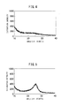
- the position of the d002 diffraction line which is normally seen in graphite crystals was 2 ⁇ ( ⁇ 26.5 degrees), but in Examples 1 to 6 of the present invention, a peak corresponding to the 002 diffraction line is present between the diffraction angle (2 ⁇ : degrees) of 20 to 30 degrees and a peak with a half value width of 0.1 degree to 1.0 degree was observed at 25.5 to 26.5 degrees. This state is shown in FIG. 1 .
- the carbon material for catalyst support use of the present invention is obtained by the following method. Further, the results of evaluation of the carbon materials of Examples 1 to 6, Comparative Examples 1 to 4, and Reference Examples 1 to 3 are shown in Table 1.
- This intermediate product was washed by concentrated nitric acid for 1 hour to dissolve away the silver which remained at the surface etc. as silver nitrate and to dissolve away unstable carbon compounds.
- the intermediate product from which these were dissolved away was rinsed, then placed in a graphite crucible and heat treated in an argon atmosphere in a graphitization furnace at 1600°C for 2 hours (second heat treatment) to obtain a carbon material for catalyst support use.
- An example of the XRD of the carbon material which was obtained in Example 1 is shown in FIG. 1 .
- An enlargement of the extent of angle of FIG. 1 is shown in FIG. 2 . From the chart of FIG. 2 , the peak position and half value width of the peak were found.
- Example 1 An SEM image of the carbon material which was obtained in Example 1 is shown in FIG. 6 .
- the diameter of the dendritic part was about 60 nm, while the length was 130 nm.
- Example 1 Except for making the temperature of the second heat treatment 1800°C, the same procedure was performed as in Example 1 to obtain a carbon material.
- Example 1 Except for making the temperature of the second heat treatment 2000°C and making the treatment time 0.5 hour, the same procedure was performed as in Example 1 to obtain a carbon material.
- Example 3 Except for making the heating time of the second heat treatment 2 hours, the same procedure was performed as in Example 3 to obtain a carbon material.
- Example 3 Except for making the heating time of the second heat treatment 4 hours, the same procedure was performed as in Example 3 to obtain a carbon material.
- An example of the XRD of the carbon material which is obtained at Example 5 is shown in FIG. 3 .
- Example 1 Except for making the temperature of the second heat treatment 2200°C, the same procedure was performed as in Example 1 to obtain a carbon material.
- Example 2 Except for making the temperature of the second heat treatment 200°C, the same procedure was performed as in Example 1 to obtain a carbon material.
- An example of the XRD of the carbon material which is obtained at Comparative Example 1 is shown in FIG. 4 .
- Example 1 Except for making the temperature of the second heat treatment 800°C, the same procedure was performed as in Example 1 to obtain a carbon material.
- Example 1 Except for making the temperature of the second heat treatment 1200°C, the same procedure was performed as in Example 1 to obtain a carbon material.
- Example 7 Except for making the temperature of the second heat treatment 2600°C, the same procedure was performed as in Example 1 to obtain a carbon material.
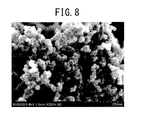
- a SEM image of the carbon material which is obtained at Comparative Example 4 is shown in FIG. 7 .
- samples of the carbon material ketjen black (made by Lion, trade name: EC600JD) used in the past as a catalyst support of a polymer electrolyte fuel cell were prepared.
- Samples with no heat treatment (Reference Example 1), samples with heat treatment at 1800°C (Reference Example 2), and samples with heat treatment at 2000°C (Reference Example 3) were processed by methods similar to the examples and were similarly measured for BET specific surface area S, cumulative pore volume, V 10 /S (Q value), and presence of dendritic structures.
- Examples 1 to 6 have structures which have both suitably grown stacked structures of graphene and amorphous structures comprised of nanosize graphene derived from the mesoporous pore structures. Furthermore, these carbon materials have dendritic structures.
- the catalyst dispersability is good and the moisture retention characteristic of the catalyst layer when made into a cell becomes a range suitable for operation in a low moisture environment.
- Comparative Examples 1 to 3 there were dendritic structures, but the graphene was insufficiently stacked, while in Reference Examples 1 to 3, there were no dendritic structures and, judging from the shape of the X-ray diffraction spectrum and value of the Q-value, it was learned that the dispersability of the catalyst and the diffusibility of the gas or the water produced when made into a fuel cell are not sufficient compared with the carbon material of the present invention.
- the carbon materials of Examples 1 to 6 and Comparative Examples 1 to 4 were used as catalyst supports to prepare metal-containing catalysts.
- the durability as a fuel cell was evaluated in the following way. Platinum was used as the catalyst seed, and the cell performance was evaluated using a fuel cell measurement apparatus for initial performance and results in a cycle deterioration test. The results of evaluation are shown in Table 1.
- a chloroplatinic aqueous solution and polyvinyl pyrrolidone were placed in distilled water and stirred at 90°C while pouring in sodium borohydride dissolved in distilled water so as to reduce the chloroplatinic acid.
- the carbon material of each of Examples 1 to 6 and Comparative Examples 1 to 4 was added and stirred for 60 minutes, then filtered and washed.
- the obtained solids were dried at 90°C in vacuum, then pulverized and heat treated in a hydrogen atmosphere at 250°C for 1 hour to thereby prepare a catalyst for fuel cell use. Further, the amount of supported platinum of the catalyst was adjusted to 30 mass%.
- the particle size of the platinum particles was estimated by the formula of Scherrer from the half value width of the platinum (111) peak in the powder X-ray diffraction spectrum of the catalyst obtained by using an X-ray diffraction apparatus (made by Rigaku, RAD).
- the catalyst was added in a stream of argon to a 5%-Nafion solution (made by Aldrich) to give a mass of the Nafion solids of 3 times the mass of the catalyst.
- the mixture was lightly stirred, then ultrasonic waves were used to crush the catalyst.
- Butyl acetate was added while stirring to give a solids concentration of the platinum catalyst and Nafion combined of 2 mass% and thereby prepare a catalyst layer slurry.
- the catalyst layer slurry was coated on a single surface of a Teflon® sheet by the spray method and dried in an 80°C stream of argon for 10 minutes, then dried in a 120°C stream of argon for 1 hour to obtain an electrode sheet with a catalyst contained in the catalyst layer. Further, the spray conditions etc. were set so that the electrode sheet had an amount of platinum used of 0.15 mg/cm 2 . The amount of platinum used was found by measuring the dry mass of the Teflon® sheet before and after spraying and calculating the difference.
- the prepared MEAs were loaded into commercially available fuel cell measuring devices and measured for cell performance.
- the cell performance was measured by changing the voltage between cell terminals from the no-load voltage (normally 0.9 to 1.0V) to 0.2V in stages and measuring the current density when the voltage between cell terminals is 0.8V. Further, as the durability test, a cycle of holding the assemblies at the no-load voltage for 15 seconds and holding the voltage across the cell terminals at 0.5V for 15 seconds was performed 4000 times, then the cell performance was measured in the same way as before the durability test.
- For the gas air was supplied to the cathode and pure hydrogen as supplied to the anode to give rates of utilization of respectively 50% and 80%.
- the respective gas pressures were adjusted to 0.1 MPa by backing pressure valves which were provided downstream of the cell.
- the cell temperature was set to 70°C, while the supplied air and pure hydrogen were respectively bubbled in distilled water which was warmed to 50°C to wet them.
- the cell characteristics were evaluated by the amount of current (mA/cm 2 ) per platinum unit area.
- Graphite is generally high in oxidation resistance, so using graphite for a support is effective for improvement of the durability of a cell.
- the practice has been to pretreat the carbon in advance to activate it to a high degree, secure a large BET surface area, then secure the pore structures after heat treatment.
- the present invention uses dendritic carbon material comprised of nanosize graphene as a starting material and heat treats this (second heat treatment) to impart a structure having both suitably grown graphene stacked structures and amorphous structures comprised of nanosize graphene derived from the mesoporous pore structures.
- the carbon material of PLT 1 when used as a support, it is possible to secure gas diffusibility and catalyst activity derived from nanosize graphene and thereby otherwise secure initial performance and doubly achieve durability, so a high cell performance is exhibited.
- the carbon material of the present invention is a material which is effective not only for applications of a metal-carrying catalyst support which is introduced here, but also fields in which diffusibility of the gas or liquid is demanded, for example, activated carbon electrodes for electric double-layer capacitor use, air electrodes of lithium air secondary batteries, etc.
Landscapes
- Chemical & Material Sciences (AREA)
- Organic Chemistry (AREA)
- Engineering & Computer Science (AREA)
- Materials Engineering (AREA)
- Chemical Kinetics & Catalysis (AREA)
- Life Sciences & Earth Sciences (AREA)
- General Life Sciences & Earth Sciences (AREA)
- Geology (AREA)
- Inorganic Chemistry (AREA)
- General Chemical & Material Sciences (AREA)
- Electrochemistry (AREA)
- Physics & Mathematics (AREA)
- Optics & Photonics (AREA)
- Health & Medical Sciences (AREA)
- Plasma & Fusion (AREA)
- Toxicology (AREA)
- Catalysts (AREA)
- Carbon And Carbon Compounds (AREA)
- Inert Electrodes (AREA)
- Nanotechnology (AREA)
- Thermal Sciences (AREA)
Applications Claiming Priority (2)
| Application Number | Priority Date | Filing Date | Title |
|---|---|---|---|
| JP2013032456 | 2013-02-21 | ||
| PCT/JP2014/054228 WO2014129597A1 (fr) | 2013-02-21 | 2014-02-21 | Matière de carbone en vue d'une utilisation comme support de catalyseur |
Publications (3)
| Publication Number | Publication Date |
|---|---|
| EP2959970A1 true EP2959970A1 (fr) | 2015-12-30 |
| EP2959970A4 EP2959970A4 (fr) | 2016-09-28 |
| EP2959970B1 EP2959970B1 (fr) | 2018-12-05 |
Family
ID=51391377
Family Applications (1)
| Application Number | Title | Priority Date | Filing Date |
|---|---|---|---|
| EP14754099.1A Active EP2959970B1 (fr) | 2013-02-21 | 2014-02-21 | Matièriau de carbone pour une utilisation de support de catalyseur |
Country Status (7)
| Country | Link |
|---|---|
| US (1) | US20150352522A1 (fr) |
| EP (1) | EP2959970B1 (fr) |
| JP (1) | JP6198810B2 (fr) |
| KR (1) | KR101762258B1 (fr) |
| CN (1) | CN105073260B (fr) |
| CA (1) | CA2899131C (fr) |
| WO (1) | WO2014129597A1 (fr) |
Cited By (8)
| Publication number | Priority date | Publication date | Assignee | Title |
|---|---|---|---|---|
| EP3214680A4 (fr) * | 2014-10-29 | 2017-11-08 | Nissan Motor Co., Ltd | Catalyseur d'électrode pour pile à combustible, couche de catalyseur d'électrode pour pile à combustible, son procédé de production et ensemble membrane-électrode et pile à combustible utilisant une couche de catalyseur |
| EP3214678A4 (fr) * | 2014-10-29 | 2017-11-15 | Nissan Motor Co., Ltd | Catalyseur d'électrode pour pile à combustible, son procédé de fabrication, couche de catalyseur d'électrode de pile à combustible contenant ledit catalyseur, ensemble membrane-électrodes de pile à combustible utilisant ledit catalyseur ou ladite couche de catalyseur, et pile à combustible |
| EP3214679A4 (fr) * | 2014-10-29 | 2017-11-22 | Nissan Motor Co., Ltd | Couche de catalyseur d'électrode pour pile à combustible, son procédé de fabrication, et ensemble d'électrodes à membrane et pile à combustible l'utilisant |
| EP3214681A4 (fr) * | 2014-10-29 | 2018-01-24 | Nissan Motor Co., Ltd | Couche de catalyseur d'électrode pour pile à combustible, ensemble membrane-électrodes de pile à combustible et pile à combustible utilisant ladite couche de catalyseur |
| EP3858481A4 (fr) * | 2018-09-28 | 2022-05-04 | NIPPON STEEL Chemical & Material Co., Ltd. | Matériau carboné destiné à un support de catalyseur de pile à combustible à polymère solide et son procédé de fabrication |
| DE102021108985A1 (de) | 2021-04-12 | 2022-10-13 | Bayerische Motoren Werke Aktiengesellschaft | Verfahren zum Herstellen eines Kohlenstoffmaterials, Kohlenstoffmaterial und Verwendung eines Kohlenstoffmaterials in einer Brennstoffzelle |
| EP3978112A4 (fr) * | 2019-06-03 | 2023-06-21 | Toyo Tanso Co., Ltd. | Catalyseur au platine supporté, cathode pour pile à combustible, pile à combustible et procédé de production d'un catalyseur au platine supporté |
| EP4439739A4 (fr) * | 2021-11-22 | 2026-03-04 | Toyo Tanso Co | Support de carbone pour catalyseur de pile à combustible et catalyseur de pile à combustible |
Families Citing this family (42)
| Publication number | Priority date | Publication date | Assignee | Title |
|---|---|---|---|---|
| US10573901B2 (en) | 2013-04-25 | 2020-02-25 | Tanaka Kikinzoku Kogyo K.K. | Catalyst and manufacturing method thereof, and electrode catalyst layer using the catalyst |
| CN105142784A (zh) | 2013-04-25 | 2015-12-09 | 日产自动车株式会社 | 催化剂以及使用该催化剂的电极催化剂层、膜电极接合体及燃料电池 |
| JP6063039B2 (ja) * | 2013-05-16 | 2017-01-18 | トヨタ自動車株式会社 | 燃料電池用電極およびその製造方法 |
| CN105814723B (zh) * | 2013-12-13 | 2018-09-11 | 新日铁住金株式会社 | 固体高分子型燃料电池用的载体碳材料和担载有金属催化剂粒子的碳材料、以及它们的制造方法 |
| KR20160138973A (ko) | 2014-03-31 | 2016-12-06 | 미쓰이금속광업주식회사 | 막전극 접합체 및 그것을 사용한 고체 고분자형 연료 전지 |
| EP3162761B1 (fr) * | 2014-06-23 | 2020-12-23 | Toray Industries, Inc. | Matériau carboné poreux |
| CN104445164B (zh) * | 2014-11-18 | 2016-09-14 | 扬州大学 | 一种在单层石墨烯膜上可控生长纳米结构的方法 |
| US9534855B2 (en) * | 2014-11-20 | 2017-01-03 | General Electric Company | High specific area composite foam and an associated method of fabrication |
| WO2016088716A1 (fr) * | 2014-12-05 | 2016-06-09 | 日清紡ホールディングス株式会社 | Catalyseur au carbone, électrode et batterie |
| US10886539B2 (en) | 2015-02-18 | 2021-01-05 | Nippon Steel Chemical & Material Co., Ltd. | Catalyst-carrier carbon material, solid-polymer fuel cell catalyst, solid-polymer fuel cell, and method for manufacturing catalyst-carrier carbon material |
| JP2018081740A (ja) * | 2015-03-23 | 2018-05-24 | 日産自動車株式会社 | 燃料電池用炭素粉末ならびに当該燃料電池用炭素粉末を用いる触媒、電極触媒層、膜電極接合体および燃料電池 |
| CN107210449B (zh) * | 2015-03-26 | 2020-08-14 | 日铁化学材料株式会社 | 固体高分子型燃料电池用载体碳材料以及催化剂 |
| CN105633418B (zh) * | 2015-12-25 | 2018-09-14 | 华南理工大学 | 一种锂空电池阴极用Pt/UIO-66复合材料及其制法 |
| JP6347259B2 (ja) * | 2016-01-15 | 2018-06-27 | トヨタ自動車株式会社 | 燃料電池用触媒層の製造方法 |
| CA3017300C (fr) | 2016-03-11 | 2020-11-10 | Nissan Motor Co., Ltd. | Poudre de carbone pour piles a combustible, catalyseur utilisant ladite poudre de carbone pour piles a combustible, couche de catalyseur d'electrode, ensemble membrane-electrodes et pile a combustible |
| WO2018003697A1 (fr) * | 2016-06-30 | 2018-01-04 | タツタ電線株式会社 | Bioélectrode et procédé de production de bioélectrode |
| CN109310355B (zh) | 2016-06-30 | 2022-03-22 | 拓自达电线株式会社 | 电极材料 |
| JP6703911B2 (ja) * | 2016-07-14 | 2020-06-03 | 日本製鉄株式会社 | 燃料電池用触媒層、触媒担体用炭素材料、及び触媒担体用炭素材料の製造方法 |
| JP6879686B2 (ja) * | 2016-07-21 | 2021-06-02 | 日本製鉄株式会社 | 多孔質炭素材料の製造方法 |
| US12142770B2 (en) | 2017-03-31 | 2024-11-12 | Nippon Steel Chemical & Material Co., Ltd. | Carbon material for use as catalyst carrier of polymer electrolyte fuel cell and method of producing the same |
| JP6854685B2 (ja) * | 2017-03-31 | 2021-04-07 | 日鉄ケミカル&マテリアル株式会社 | 固体高分子形燃料電池の触媒担体用炭素材料及びその製造方法、並びに前記触媒担体用炭素材料を用いた固体高分子形燃料電池用触媒担体 |
| CA3058386C (fr) * | 2017-03-31 | 2021-11-02 | Nippon Steel Chemical & Material Co., Ltd. | Materiau carbone pour support catalytique de pile a combustible a polymere solide et son procede de fabrication |
| EP3621136B1 (fr) * | 2017-03-31 | 2022-01-26 | NIPPON STEEL Chemical & Material Co., Ltd. | Matériau carboné pour support de catalyseur de pile à combustible à polymère électrolytique, et son procédé de fabrication |
| JP6635976B2 (ja) | 2017-04-28 | 2020-01-29 | 株式会社キャタラー | 燃料電池用電極触媒及びその製造方法 |
| JP6772952B2 (ja) * | 2017-05-10 | 2020-10-21 | トヨタ自動車株式会社 | 燃料電池電極用触媒層及び燃料電池 |
| JP6923371B2 (ja) * | 2017-06-23 | 2021-08-18 | トヨタ自動車株式会社 | 燃料電池用電極触媒 |
| EP3648213A4 (fr) * | 2017-06-29 | 2021-03-17 | Nippon Steel Corporation | Support de catalyseur de pile à combustible du type polymère solide, procédé de fabrication de support de catalyseur de pile à combustible du type polymère solide, couche de catalyseur pour pile à combustible du type polymère solide et pile à combustible |
| WO2019177060A1 (fr) | 2018-03-16 | 2019-09-19 | 株式会社キャタラー | Catalyseur d'électrode pour pile à combustible et pile à combustible l'utilisant |
| JP7151524B2 (ja) * | 2019-02-06 | 2022-10-12 | トヨタ自動車株式会社 | 燃料電池用触媒 |
| JP7175857B2 (ja) | 2019-08-02 | 2022-11-21 | 日清紡ホールディングス株式会社 | 金属担持触媒、電池電極及び電池 |
| JP7158350B2 (ja) | 2019-08-02 | 2022-10-21 | 日清紡ホールディングス株式会社 | 金属担持触媒、電池電極及び電池 |
| JP7130311B2 (ja) | 2019-08-02 | 2022-09-05 | 日清紡ホールディングス株式会社 | 金属担持触媒、電池電極及び電池 |
| JP7153005B2 (ja) | 2019-11-29 | 2022-10-13 | 株式会社豊田中央研究所 | メソ多孔カーボン及びその製造方法、並びに、固体高分子形燃料電池 |
| CN111977633A (zh) * | 2020-07-29 | 2020-11-24 | 扬州大学 | 一种微波法制备磷/氧掺杂纳米多孔碳材料的方法 |
| JP7605606B2 (ja) | 2020-10-19 | 2024-12-24 | 日鉄ケミカル&マテリアル株式会社 | 固体高分子形燃料電池触媒担体用炭素材料、固体高分子形燃料電池用触媒層、及び燃料電池 |
| EP4235877A4 (fr) | 2020-10-21 | 2025-04-09 | Kolon Industries, Inc. | Support à base de carbone pour catalyseur de pile à combustible, catalyseur le comprenant, ensemble membrane-électrode le comprenant et son procédé de préparation |
| JP7284776B2 (ja) | 2021-03-30 | 2023-05-31 | 株式会社豊田中央研究所 | メソポーラスカーボン、並びに、燃料電池用電極触媒及び触媒層 |
| JP7655761B2 (ja) * | 2021-03-31 | 2025-04-02 | 日鉄ケミカル&マテリアル株式会社 | 固体高分子形燃料電池の触媒担体用炭素材料及びその製造方法 |
| CN113697794B (zh) * | 2021-08-31 | 2023-08-08 | 广东工业大学 | 一种慢速控温法制备树枝状超细水热碳的方法及制成的水热碳吸附球和应用 |
| KR102695039B1 (ko) * | 2022-06-17 | 2024-08-12 | 희성촉매 주식회사 | 메조 다공 카본의 제조 방법 및 이에 의해 제조된 메조 다공 카본 |
| EP4693525A1 (fr) * | 2023-03-31 | 2026-02-11 | Nippon Steel Chemical & Material Co., Ltd. | Matière carbonée pour support de catalyseur de pile à combustible à polymère solide, couche de catalyseur pour pile à combustible à polymère solide, pile à combustible et procédé de fabrication de matière carbonée pour support de catalyseur de pile à combustible à polymère solide |
| CN116395684B (zh) * | 2023-04-28 | 2024-11-22 | 陕西科技大学 | 一种银盐催化焦炭低温下制备锂电用石墨的方法 |
Family Cites Families (8)
| Publication number | Priority date | Publication date | Assignee | Title |
|---|---|---|---|---|
| KR100708642B1 (ko) | 2003-11-21 | 2007-04-18 | 삼성에스디아이 주식회사 | 중형다공성 탄소 분자체 및 이를 사용한 담지촉매 |
| WO2007137795A1 (fr) | 2006-05-31 | 2007-12-06 | MAX-PLANCK-Gesellschaft zur Förderung der Wissenschaften e.V. | Matériau carboné électriquement conducteur poreux et ses utilisations |
| JP4764866B2 (ja) | 2007-04-25 | 2011-09-07 | 関西熱化学株式会社 | 触媒担体、触媒、触媒担体の製造方法、および触媒の製造方法 |
| JP5481748B2 (ja) * | 2007-12-12 | 2014-04-23 | 新日鉄住金化学株式会社 | 炭素ナノ構造体、金属内包樹状炭素ナノ構造物の作製方法、及び炭素ナノ構造体の作製方法 |
| US9017837B2 (en) * | 2008-02-19 | 2015-04-28 | Cabot Corporation | High surface area graphitized carbon and processes for making same |
| US8492653B2 (en) * | 2008-03-19 | 2013-07-23 | Koninklijke Philips Electronics N.V. | Connector for establishing an electrical connection with conductive tape |
| US8916296B2 (en) * | 2010-03-12 | 2014-12-23 | Energ2 Technologies, Inc. | Mesoporous carbon materials comprising bifunctional catalysts |
| JP5900015B2 (ja) * | 2012-02-28 | 2016-04-06 | 日産自動車株式会社 | 燃料電池 |
-
2014
- 2014-02-21 CN CN201480009624.8A patent/CN105073260B/zh active Active
- 2014-02-21 EP EP14754099.1A patent/EP2959970B1/fr active Active
- 2014-02-21 WO PCT/JP2014/054228 patent/WO2014129597A1/fr not_active Ceased
- 2014-02-21 JP JP2015501524A patent/JP6198810B2/ja active Active
- 2014-02-21 CA CA2899131A patent/CA2899131C/fr active Active
- 2014-02-21 KR KR1020157021916A patent/KR101762258B1/ko active Active
- 2014-02-21 US US14/763,428 patent/US20150352522A1/en not_active Abandoned
Cited By (9)
| Publication number | Priority date | Publication date | Assignee | Title |
|---|---|---|---|---|
| EP3214680A4 (fr) * | 2014-10-29 | 2017-11-08 | Nissan Motor Co., Ltd | Catalyseur d'électrode pour pile à combustible, couche de catalyseur d'électrode pour pile à combustible, son procédé de production et ensemble membrane-électrode et pile à combustible utilisant une couche de catalyseur |
| EP3214678A4 (fr) * | 2014-10-29 | 2017-11-15 | Nissan Motor Co., Ltd | Catalyseur d'électrode pour pile à combustible, son procédé de fabrication, couche de catalyseur d'électrode de pile à combustible contenant ledit catalyseur, ensemble membrane-électrodes de pile à combustible utilisant ledit catalyseur ou ladite couche de catalyseur, et pile à combustible |
| EP3214679A4 (fr) * | 2014-10-29 | 2017-11-22 | Nissan Motor Co., Ltd | Couche de catalyseur d'électrode pour pile à combustible, son procédé de fabrication, et ensemble d'électrodes à membrane et pile à combustible l'utilisant |
| EP3214681A4 (fr) * | 2014-10-29 | 2018-01-24 | Nissan Motor Co., Ltd | Couche de catalyseur d'électrode pour pile à combustible, ensemble membrane-électrodes de pile à combustible et pile à combustible utilisant ladite couche de catalyseur |
| EP3858481A4 (fr) * | 2018-09-28 | 2022-05-04 | NIPPON STEEL Chemical & Material Co., Ltd. | Matériau carboné destiné à un support de catalyseur de pile à combustible à polymère solide et son procédé de fabrication |
| EP3978112A4 (fr) * | 2019-06-03 | 2023-06-21 | Toyo Tanso Co., Ltd. | Catalyseur au platine supporté, cathode pour pile à combustible, pile à combustible et procédé de production d'un catalyseur au platine supporté |
| US12126031B2 (en) | 2019-06-03 | 2024-10-22 | Toyo Tanso Co., Ltd. | Supported platinum catalyst, cathode for fuel cell, fuel cell, and method for producing supported platinum catalyst |
| DE102021108985A1 (de) | 2021-04-12 | 2022-10-13 | Bayerische Motoren Werke Aktiengesellschaft | Verfahren zum Herstellen eines Kohlenstoffmaterials, Kohlenstoffmaterial und Verwendung eines Kohlenstoffmaterials in einer Brennstoffzelle |
| EP4439739A4 (fr) * | 2021-11-22 | 2026-03-04 | Toyo Tanso Co | Support de carbone pour catalyseur de pile à combustible et catalyseur de pile à combustible |
Also Published As
| Publication number | Publication date |
|---|---|
| WO2014129597A1 (fr) | 2014-08-28 |
| CA2899131A1 (fr) | 2014-08-28 |
| KR101762258B1 (ko) | 2017-07-28 |
| CN105073260A (zh) | 2015-11-18 |
| JPWO2014129597A1 (ja) | 2017-02-02 |
| KR20150108868A (ko) | 2015-09-30 |
| EP2959970B1 (fr) | 2018-12-05 |
| EP2959970A4 (fr) | 2016-09-28 |
| CN105073260B (zh) | 2018-04-06 |
| CA2899131C (fr) | 2017-03-07 |
| JP6198810B2 (ja) | 2017-09-20 |
| US20150352522A1 (en) | 2015-12-10 |
Similar Documents
| Publication | Publication Date | Title |
|---|---|---|
| EP2959970B1 (fr) | Matièriau de carbone pour une utilisation de support de catalyseur | |
| Calvillo et al. | Platinum supported on functionalized ordered mesoporous carbon as electrocatalyst for direct methanol fuel cells | |
| Li et al. | MOF derived Co 3 O 4 nanoparticles embedded in N-doped mesoporous carbon layer/MWCNT hybrids: extraordinary bi-functional electrocatalysts for OER and ORR | |
| CN104093482B (zh) | 承载于介孔石墨颗粒上的高度烧结稳定的金属纳米颗粒及其用途 | |
| US7670582B2 (en) | Mesoporous carbon and method of producing the same | |
| Huang et al. | Novel graphite-carbon encased tungsten carbide nanocomposites by solid-state reaction and their ORR electrocatalytic performance in alkaline medium | |
| Pi et al. | Hierarchical porous activated carbon in OER with high efficiency | |
| JP2007137754A (ja) | メソ細孔性炭素とその製造方法、それを利用した担持触媒及び燃料電池 | |
| Li et al. | Nitrogen-doped hollow carbon polyhedron derived from metal-organic frameworks for supercapacitors | |
| KR101013600B1 (ko) | 콜로이달-임프린티드 탄소구조체, 그의 제조방법 및 이를이용한 연료전지 전극용 ci 탄소 담지 촉매 | |
| Kong et al. | Platinum catalyst on ordered mesoporous carbon with controlled morphology for methanol electrochemical oxidation | |
| JP7144378B2 (ja) | 燃料電池触媒担体用の黒鉛化炭素多孔体、燃料電池触媒、及び燃料電池触媒層の製造方法 | |
| CN112867564A (zh) | 固体高分子型燃料电池的催化剂载体用碳材料以及其制造方法 | |
| Zeng et al. | Method for preparing highly dispersed Pt catalysts on mesoporous carbon support | |
| Song et al. | Synthesis of novel hollow graphitic vesicle-supported Pt nanoparticles for oxygen reduction reaction | |
| CN115386899B (zh) | 一种钴镍合金/多孔碳析氧催化剂及制备方法和应用 | |
| Huang et al. | Facile synthesis of porous Pt botryoidal nanowires and their electrochemical properties | |
| KR20140121718A (ko) | 하이브리드 형태의 연료전지용 전극촉매 | |
| CN111468161B (zh) | 一种三功能钴氮双掺杂碳基光子晶体催化剂及其制备方法和应用 | |
| CN112981456A (zh) | 一种高效制备丙酮的Cu@MIL-101-Cr电催化剂的制备方法 | |
| Zhou et al. | Structural and electrochemical characterization of Pt/CMK-5 via CTAB introduced into the microwave heating process | |
| Moliner et al. | Oxidised carbon nanofibers as platinum support for proton exchange membrane (PEM) fuel cells | |
| Wang et al. | MOF-derived N-doped porous carbon nanorods supporting NiCo@ Pt for enhanced electrocatalytic methanol oxidation | |
| CN115947331B (zh) | 低电阻率氮掺杂碳材料及其制备方法和燃料电池催化剂及锂离子电池电极材料 | |
| Ramli et al. | Synthesis, characterization and potential of Pt-Ru supported carbon nanocage (CNC) for methanol oxidation reaction (MOR) and DMFC application |
Legal Events
| Date | Code | Title | Description |
|---|---|---|---|
| PUAI | Public reference made under article 153(3) epc to a published international application that has entered the european phase |
Free format text: ORIGINAL CODE: 0009012 |
|
| 17P | Request for examination filed |
Effective date: 20150824 |
|
| AK | Designated contracting states |
Kind code of ref document: A1 Designated state(s): AL AT BE BG CH CY CZ DE DK EE ES FI FR GB GR HR HU IE IS IT LI LT LU LV MC MK MT NL NO PL PT RO RS SE SI SK SM TR |
|
| AX | Request for extension of the european patent |
Extension state: BA ME |
|
| DAX | Request for extension of the european patent (deleted) | ||
| A4 | Supplementary search report drawn up and despatched |
Effective date: 20160831 |
|
| RIC1 | Information provided on ipc code assigned before grant |
Ipc: H01M 8/10 20060101ALN20160825BHEP Ipc: H01M 4/96 20060101ALN20160825BHEP Ipc: B01J 32/00 20060101ALN20160825BHEP Ipc: B01J 37/34 20060101ALN20160825BHEP Ipc: B01J 37/08 20060101ALN20160825BHEP Ipc: B01J 35/00 20060101ALN20160825BHEP Ipc: B01J 23/50 20060101ALN20160825BHEP Ipc: C01B 31/04 20060101ALI20160825BHEP Ipc: B01J 21/18 20060101ALI20160825BHEP Ipc: B01J 23/42 20060101AFI20160825BHEP Ipc: H01M 4/92 20060101ALI20160825BHEP Ipc: H01M 4/90 20060101ALI20160825BHEP Ipc: B01J 35/10 20060101ALI20160825BHEP Ipc: B01J 37/06 20060101ALN20160825BHEP |
|
| REG | Reference to a national code |
Ref country code: DE Ref legal event code: R079 Ref document number: 602014037439 Country of ref document: DE Free format text: PREVIOUS MAIN CLASS: B01J0037080000 Ipc: B01J0023420000 |
|
| RIC1 | Information provided on ipc code assigned before grant |
Ipc: H01M 4/92 20060101ALI20180206BHEP Ipc: B01J 37/06 20060101ALN20180206BHEP Ipc: C01B 32/20 20170101ALI20180206BHEP Ipc: B01J 32/00 20060101ALN20180206BHEP Ipc: B01J 35/10 20060101ALI20180206BHEP Ipc: B01J 23/42 20060101AFI20180206BHEP Ipc: B01J 37/34 20060101ALN20180206BHEP Ipc: H01M 8/10 20160101ALN20180206BHEP Ipc: H01M 4/90 20060101ALI20180206BHEP Ipc: H01M 4/96 20060101ALN20180206BHEP Ipc: B01J 35/00 20060101ALN20180206BHEP Ipc: B01J 23/50 20060101ALN20180206BHEP Ipc: B01J 21/18 20060101ALI20180206BHEP Ipc: B01J 37/08 20060101ALN20180206BHEP |
|
| GRAP | Despatch of communication of intention to grant a patent |
Free format text: ORIGINAL CODE: EPIDOSNIGR1 |
|
| STAA | Information on the status of an ep patent application or granted ep patent |
Free format text: STATUS: GRANT OF PATENT IS INTENDED |
|
| INTG | Intention to grant announced |
Effective date: 20180320 |
|
| GRAS | Grant fee paid |
Free format text: ORIGINAL CODE: EPIDOSNIGR3 |
|
| GRAA | (expected) grant |
Free format text: ORIGINAL CODE: 0009210 |
|
| STAA | Information on the status of an ep patent application or granted ep patent |
Free format text: STATUS: THE PATENT HAS BEEN GRANTED |
|
| AK | Designated contracting states |
Kind code of ref document: B1 Designated state(s): AL AT BE BG CH CY CZ DE DK EE ES FI FR GB GR HR HU IE IS IT LI LT LU LV MC MK MT NL NO PL PT RO RS SE SI SK SM TR |
|
| REG | Reference to a national code |
Ref country code: GB Ref legal event code: FG4D |
|
| REG | Reference to a national code |
Ref country code: CH Ref legal event code: EP |
|
| REG | Reference to a national code |
Ref country code: AT Ref legal event code: REF Ref document number: 1072375 Country of ref document: AT Kind code of ref document: T Effective date: 20181215 |
|
| REG | Reference to a national code |
Ref country code: IE Ref legal event code: FG4D |
|
| REG | Reference to a national code |
Ref country code: DE Ref legal event code: R096 Ref document number: 602014037439 Country of ref document: DE |
|
| REG | Reference to a national code |
Ref country code: CH Ref legal event code: PK Free format text: BERICHTIGUNGEN |
|
| RIC2 | Information provided on ipc code assigned after grant |
Ipc: H01M 4/92 20060101ALI20180206BHEP Ipc: B01J 35/00 20060101ALN20180206BHEP Ipc: H01M 4/96 20060101ALN20180206BHEP Ipc: B01J 21/18 20060101ALI20180206BHEP Ipc: H01M 8/10 20160101ALN20180206BHEP Ipc: B01J 37/08 20060101ALN20180206BHEP Ipc: B01J 32/00 20060101ALN20180206BHEP Ipc: B01J 37/06 20060101ALN20180206BHEP Ipc: B01J 35/10 20060101ALI20180206BHEP Ipc: B01J 23/50 20060101ALN20180206BHEP Ipc: H01M 4/90 20060101ALI20180206BHEP Ipc: C01B 32/20 20170101ALI20180206BHEP Ipc: B01J 23/42 20060101AFI20180206BHEP Ipc: B01J 37/34 20060101ALN20180206BHEP |
|
| RAP2 | Party data changed (patent owner data changed or rights of a patent transferred) |
Owner name: NIPPON STEEL & SUMITOMO METAL CORPORATION Owner name: NIPPON STEEL CHEMICAL & MATERIAL CO., LTD. |
|
| REG | Reference to a national code |
Ref country code: NL Ref legal event code: MP Effective date: 20181205 |
|
| REG | Reference to a national code |
Ref country code: AT Ref legal event code: MK05 Ref document number: 1072375 Country of ref document: AT Kind code of ref document: T Effective date: 20181205 |
|
| REG | Reference to a national code |
Ref country code: DE Ref legal event code: R082 Ref document number: 602014037439 Country of ref document: DE Representative=s name: VOSSIUS & PARTNER PATENTANWAELTE RECHTSANWAELT, DE Ref country code: DE Ref legal event code: R081 Ref document number: 602014037439 Country of ref document: DE Owner name: NIPPON STEEL CHEMICAL & MATERIAL CO., LTD., JP Free format text: FORMER OWNERS: NIPPON STEEL & SUMIKIN CHEMICAL CO., LTD., TOKYO, JP; NIPPON STEEL & SUMITOMO METAL CORPORATION, TOKYO, JP Ref country code: DE Ref legal event code: R081 Ref document number: 602014037439 Country of ref document: DE Owner name: NIPPON STEEL & SUMITOMO METAL CORPORATION, JP Free format text: FORMER OWNERS: NIPPON STEEL & SUMIKIN CHEMICAL CO., LTD., TOKYO, JP; NIPPON STEEL & SUMITOMO METAL CORPORATION, TOKYO, JP Ref country code: DE Ref legal event code: R081 Ref document number: 602014037439 Country of ref document: DE Owner name: NIPPON STEEL CORPORATION, JP Free format text: FORMER OWNERS: NIPPON STEEL & SUMIKIN CHEMICAL CO., LTD., TOKYO, JP; NIPPON STEEL & SUMITOMO METAL CORPORATION, TOKYO, JP |
|
| REG | Reference to a national code |
Ref country code: LT Ref legal event code: MG4D |
|
| PG25 | Lapsed in a contracting state [announced via postgrant information from national office to epo] |
Ref country code: FI Free format text: LAPSE BECAUSE OF FAILURE TO SUBMIT A TRANSLATION OF THE DESCRIPTION OR TO PAY THE FEE WITHIN THE PRESCRIBED TIME-LIMIT Effective date: 20181205 Ref country code: LV Free format text: LAPSE BECAUSE OF FAILURE TO SUBMIT A TRANSLATION OF THE DESCRIPTION OR TO PAY THE FEE WITHIN THE PRESCRIBED TIME-LIMIT Effective date: 20181205 Ref country code: AT Free format text: LAPSE BECAUSE OF FAILURE TO SUBMIT A TRANSLATION OF THE DESCRIPTION OR TO PAY THE FEE WITHIN THE PRESCRIBED TIME-LIMIT Effective date: 20181205 Ref country code: HR Free format text: LAPSE BECAUSE OF FAILURE TO SUBMIT A TRANSLATION OF THE DESCRIPTION OR TO PAY THE FEE WITHIN THE PRESCRIBED TIME-LIMIT Effective date: 20181205 Ref country code: BG Free format text: LAPSE BECAUSE OF FAILURE TO SUBMIT A TRANSLATION OF THE DESCRIPTION OR TO PAY THE FEE WITHIN THE PRESCRIBED TIME-LIMIT Effective date: 20190305 Ref country code: LT Free format text: LAPSE BECAUSE OF FAILURE TO SUBMIT A TRANSLATION OF THE DESCRIPTION OR TO PAY THE FEE WITHIN THE PRESCRIBED TIME-LIMIT Effective date: 20181205 Ref country code: ES Free format text: LAPSE BECAUSE OF FAILURE TO SUBMIT A TRANSLATION OF THE DESCRIPTION OR TO PAY THE FEE WITHIN THE PRESCRIBED TIME-LIMIT Effective date: 20181205 Ref country code: NO Free format text: LAPSE BECAUSE OF FAILURE TO SUBMIT A TRANSLATION OF THE DESCRIPTION OR TO PAY THE FEE WITHIN THE PRESCRIBED TIME-LIMIT Effective date: 20190305 |
|
| PG25 | Lapsed in a contracting state [announced via postgrant information from national office to epo] |
Ref country code: GR Free format text: LAPSE BECAUSE OF FAILURE TO SUBMIT A TRANSLATION OF THE DESCRIPTION OR TO PAY THE FEE WITHIN THE PRESCRIBED TIME-LIMIT Effective date: 20190306 Ref country code: RS Free format text: LAPSE BECAUSE OF FAILURE TO SUBMIT A TRANSLATION OF THE DESCRIPTION OR TO PAY THE FEE WITHIN THE PRESCRIBED TIME-LIMIT Effective date: 20181205 Ref country code: AL Free format text: LAPSE BECAUSE OF FAILURE TO SUBMIT A TRANSLATION OF THE DESCRIPTION OR TO PAY THE FEE WITHIN THE PRESCRIBED TIME-LIMIT Effective date: 20181205 Ref country code: SE Free format text: LAPSE BECAUSE OF FAILURE TO SUBMIT A TRANSLATION OF THE DESCRIPTION OR TO PAY THE FEE WITHIN THE PRESCRIBED TIME-LIMIT Effective date: 20181205 |
|
| REG | Reference to a national code |
Ref country code: DE Ref legal event code: R082 Ref document number: 602014037439 Country of ref document: DE Representative=s name: VOSSIUS & PARTNER PATENTANWAELTE RECHTSANWAELT, DE Ref country code: DE Ref legal event code: R081 Ref document number: 602014037439 Country of ref document: DE Owner name: NIPPON STEEL CORPORATION, JP Free format text: FORMER OWNERS: NIPPON STEEL & SUMITOMO METAL CORPORATION, TOKYO, JP; NIPPON STEEL CHEMICAL & MATERIAL CO., LTD., TOKYO, JP Ref country code: DE Ref legal event code: R081 Ref document number: 602014037439 Country of ref document: DE Owner name: NIPPON STEEL CHEMICAL & MATERIAL CO., LTD., JP Free format text: FORMER OWNERS: NIPPON STEEL & SUMITOMO METAL CORPORATION, TOKYO, JP; NIPPON STEEL CHEMICAL & MATERIAL CO., LTD., TOKYO, JP |
|
| PG25 | Lapsed in a contracting state [announced via postgrant information from national office to epo] |
Ref country code: NL Free format text: LAPSE BECAUSE OF FAILURE TO SUBMIT A TRANSLATION OF THE DESCRIPTION OR TO PAY THE FEE WITHIN THE PRESCRIBED TIME-LIMIT Effective date: 20181205 |
|
| RAP2 | Party data changed (patent owner data changed or rights of a patent transferred) |
Owner name: NIPPON STEEL CHEMICAL & MATERIAL CO., LTD. Owner name: NIPPON STEEL CORPORATION |
|
| PG25 | Lapsed in a contracting state [announced via postgrant information from national office to epo] |
Ref country code: CZ Free format text: LAPSE BECAUSE OF FAILURE TO SUBMIT A TRANSLATION OF THE DESCRIPTION OR TO PAY THE FEE WITHIN THE PRESCRIBED TIME-LIMIT Effective date: 20181205 Ref country code: IT Free format text: LAPSE BECAUSE OF FAILURE TO SUBMIT A TRANSLATION OF THE DESCRIPTION OR TO PAY THE FEE WITHIN THE PRESCRIBED TIME-LIMIT Effective date: 20181205 Ref country code: PT Free format text: LAPSE BECAUSE OF FAILURE TO SUBMIT A TRANSLATION OF THE DESCRIPTION OR TO PAY THE FEE WITHIN THE PRESCRIBED TIME-LIMIT Effective date: 20190405 Ref country code: PL Free format text: LAPSE BECAUSE OF FAILURE TO SUBMIT A TRANSLATION OF THE DESCRIPTION OR TO PAY THE FEE WITHIN THE PRESCRIBED TIME-LIMIT Effective date: 20181205 |
|
| PG25 | Lapsed in a contracting state [announced via postgrant information from national office to epo] |
Ref country code: EE Free format text: LAPSE BECAUSE OF FAILURE TO SUBMIT A TRANSLATION OF THE DESCRIPTION OR TO PAY THE FEE WITHIN THE PRESCRIBED TIME-LIMIT Effective date: 20181205 Ref country code: SM Free format text: LAPSE BECAUSE OF FAILURE TO SUBMIT A TRANSLATION OF THE DESCRIPTION OR TO PAY THE FEE WITHIN THE PRESCRIBED TIME-LIMIT Effective date: 20181205 Ref country code: SK Free format text: LAPSE BECAUSE OF FAILURE TO SUBMIT A TRANSLATION OF THE DESCRIPTION OR TO PAY THE FEE WITHIN THE PRESCRIBED TIME-LIMIT Effective date: 20181205 Ref country code: IS Free format text: LAPSE BECAUSE OF FAILURE TO SUBMIT A TRANSLATION OF THE DESCRIPTION OR TO PAY THE FEE WITHIN THE PRESCRIBED TIME-LIMIT Effective date: 20190405 Ref country code: RO Free format text: LAPSE BECAUSE OF FAILURE TO SUBMIT A TRANSLATION OF THE DESCRIPTION OR TO PAY THE FEE WITHIN THE PRESCRIBED TIME-LIMIT Effective date: 20181205 |
|
| REG | Reference to a national code |
Ref country code: DE Ref legal event code: R097 Ref document number: 602014037439 Country of ref document: DE |
|
| REG | Reference to a national code |
Ref country code: CH Ref legal event code: PL |
|
| PLBE | No opposition filed within time limit |
Free format text: ORIGINAL CODE: 0009261 |
|
| STAA | Information on the status of an ep patent application or granted ep patent |
Free format text: STATUS: NO OPPOSITION FILED WITHIN TIME LIMIT |
|
| PG25 | Lapsed in a contracting state [announced via postgrant information from national office to epo] |
Ref country code: SI Free format text: LAPSE BECAUSE OF FAILURE TO SUBMIT A TRANSLATION OF THE DESCRIPTION OR TO PAY THE FEE WITHIN THE PRESCRIBED TIME-LIMIT Effective date: 20181205 Ref country code: MC Free format text: LAPSE BECAUSE OF FAILURE TO SUBMIT A TRANSLATION OF THE DESCRIPTION OR TO PAY THE FEE WITHIN THE PRESCRIBED TIME-LIMIT Effective date: 20181205 Ref country code: DK Free format text: LAPSE BECAUSE OF FAILURE TO SUBMIT A TRANSLATION OF THE DESCRIPTION OR TO PAY THE FEE WITHIN THE PRESCRIBED TIME-LIMIT Effective date: 20181205 Ref country code: LU Free format text: LAPSE BECAUSE OF NON-PAYMENT OF DUE FEES Effective date: 20190221 |
|
| 26N | No opposition filed |
Effective date: 20190906 |
|
| REG | Reference to a national code |
Ref country code: BE Ref legal event code: MM Effective date: 20190228 |
|
| REG | Reference to a national code |
Ref country code: IE Ref legal event code: MM4A |
|
| PG25 | Lapsed in a contracting state [announced via postgrant information from national office to epo] |
Ref country code: CH Free format text: LAPSE BECAUSE OF NON-PAYMENT OF DUE FEES Effective date: 20190228 Ref country code: LI Free format text: LAPSE BECAUSE OF NON-PAYMENT OF DUE FEES Effective date: 20190228 |
|
| PG25 | Lapsed in a contracting state [announced via postgrant information from national office to epo] |
Ref country code: IE Free format text: LAPSE BECAUSE OF NON-PAYMENT OF DUE FEES Effective date: 20190221 |
|
| PG25 | Lapsed in a contracting state [announced via postgrant information from national office to epo] |
Ref country code: BE Free format text: LAPSE BECAUSE OF NON-PAYMENT OF DUE FEES Effective date: 20190228 |
|
| PG25 | Lapsed in a contracting state [announced via postgrant information from national office to epo] |
Ref country code: TR Free format text: LAPSE BECAUSE OF FAILURE TO SUBMIT A TRANSLATION OF THE DESCRIPTION OR TO PAY THE FEE WITHIN THE PRESCRIBED TIME-LIMIT Effective date: 20181205 |
|
| PG25 | Lapsed in a contracting state [announced via postgrant information from national office to epo] |
Ref country code: MT Free format text: LAPSE BECAUSE OF NON-PAYMENT OF DUE FEES Effective date: 20190221 |
|
| REG | Reference to a national code |
Ref country code: DE Ref legal event code: R082 Ref document number: 602014037439 Country of ref document: DE Representative=s name: VOSSIUS & PARTNER PATENTANWAELTE RECHTSANWAELT, DE Ref country code: DE Ref legal event code: R081 Ref document number: 602014037439 Country of ref document: DE Owner name: NIPPON STEEL CHEMICAL & MATERIAL CO., LTD., JP Free format text: FORMER OWNERS: NIPPON STEEL CHEMICAL & MATERIAL CO., LTD., TOKYO, JP; NIPPON STEEL CORPORATION, TOKYO, JP |
|
| PG25 | Lapsed in a contracting state [announced via postgrant information from national office to epo] |
Ref country code: CY Free format text: LAPSE BECAUSE OF FAILURE TO SUBMIT A TRANSLATION OF THE DESCRIPTION OR TO PAY THE FEE WITHIN THE PRESCRIBED TIME-LIMIT Effective date: 20181205 |
|
| REG | Reference to a national code |
Ref country code: GB Ref legal event code: 732E Free format text: REGISTERED BETWEEN 20210617 AND 20210623 |
|
| PG25 | Lapsed in a contracting state [announced via postgrant information from national office to epo] |
Ref country code: HU Free format text: LAPSE BECAUSE OF FAILURE TO SUBMIT A TRANSLATION OF THE DESCRIPTION OR TO PAY THE FEE WITHIN THE PRESCRIBED TIME-LIMIT; INVALID AB INITIO Effective date: 20140221 |
|
| PG25 | Lapsed in a contracting state [announced via postgrant information from national office to epo] |
Ref country code: MK Free format text: LAPSE BECAUSE OF FAILURE TO SUBMIT A TRANSLATION OF THE DESCRIPTION OR TO PAY THE FEE WITHIN THE PRESCRIBED TIME-LIMIT Effective date: 20181205 |
|
| P01 | Opt-out of the competence of the unified patent court (upc) registered |
Effective date: 20230509 |
|
| PGFP | Annual fee paid to national office [announced via postgrant information from national office to epo] |
Ref country code: FR Payment date: 20251231 Year of fee payment: 13 |
|
| PGFP | Annual fee paid to national office [announced via postgrant information from national office to epo] |
Ref country code: GB Payment date: 20260106 Year of fee payment: 13 |
|
| PGFP | Annual fee paid to national office [announced via postgrant information from national office to epo] |
Ref country code: DE Payment date: 20251230 Year of fee payment: 13 |