EP2960200A1 - Verschliessmaschine - Google Patents
Verschliessmaschine Download PDFInfo
- Publication number
- EP2960200A1 EP2960200A1 EP14174000.1A EP14174000A EP2960200A1 EP 2960200 A1 EP2960200 A1 EP 2960200A1 EP 14174000 A EP14174000 A EP 14174000A EP 2960200 A1 EP2960200 A1 EP 2960200A1
- Authority
- EP
- European Patent Office
- Prior art keywords
- container
- machine
- plunger
- closed end
- axis
- Prior art date
- Legal status (The legal status is an assumption and is not a legal conclusion. Google has not performed a legal analysis and makes no representation as to the accuracy of the status listed.)
- Withdrawn
Links
Images


Classifications
-
- B—PERFORMING OPERATIONS; TRANSPORTING
- B67—OPENING, CLOSING OR CLEANING BOTTLES, JARS OR SIMILAR CONTAINERS; LIQUID HANDLING
- B67B—APPLYING CLOSURE MEMBERS TO BOTTLES JARS, OR SIMILAR CONTAINERS; OPENING CLOSED CONTAINERS
- B67B3/00—Closing bottles, jars or similar containers by applying caps
- B67B3/20—Closing bottles, jars or similar containers by applying caps by applying and rotating preformed threaded caps
- B67B3/2013—Closing bottles, jars or similar containers by applying caps by applying and rotating preformed threaded caps by carousel-type capping machines
- B67B3/2033—Closing bottles, jars or similar containers by applying caps by applying and rotating preformed threaded caps by carousel-type capping machines comprising carousel co-rotating capping heads
-
- B—PERFORMING OPERATIONS; TRANSPORTING
- B65—CONVEYING; PACKING; STORING; HANDLING THIN OR FILAMENTARY MATERIAL
- B65B—MACHINES, APPARATUS OR DEVICES FOR, OR METHODS OF, PACKAGING ARTICLES OR MATERIALS; UNPACKING
- B65B61/00—Auxiliary devices, not otherwise provided for, for operating on sheets, blanks, webs, binding material, containers or packages
- B65B61/24—Auxiliary devices, not otherwise provided for, for operating on sheets, blanks, webs, binding material, containers or packages for shaping or reshaping completed packages
-
- B—PERFORMING OPERATIONS; TRANSPORTING
- B67—OPENING, CLOSING OR CLEANING BOTTLES, JARS OR SIMILAR CONTAINERS; LIQUID HANDLING
- B67B—APPLYING CLOSURE MEMBERS TO BOTTLES JARS, OR SIMILAR CONTAINERS; OPENING CLOSED CONTAINERS
- B67B3/00—Closing bottles, jars or similar containers by applying caps
- B67B3/28—Mechanisms for causing relative movement between bottle or jar and capping head
-
- B—PERFORMING OPERATIONS; TRANSPORTING
- B67—OPENING, CLOSING OR CLEANING BOTTLES, JARS OR SIMILAR CONTAINERS; LIQUID HANDLING
- B67C—CLEANING, FILLING WITH LIQUIDS OR SEMILIQUIDS, OR EMPTYING, OF BOTTLES, JARS, CANS, CASKS, BARRELS, OR SIMILAR CONTAINERS, NOT OTHERWISE PROVIDED FOR; FUNNELS
- B67C3/00—Bottling liquids or semiliquids; Filling jars or cans with liquids or semiliquids using bottling or like apparatus; Filling casks or barrels with liquids or semiliquids
- B67C3/02—Bottling liquids or semiliquids; Filling jars or cans with liquids or semiliquids using bottling or like apparatus
- B67C3/22—Details
- B67C2003/226—Additional process steps or apparatuses related to filling with hot liquids, e.g. after-treatment
Definitions
- the present invention relates to a capping machine for applying caps on respective open ends of containers made of a deformable material and filled with a pourable product, such as a non-carbonated liquid product.
- the containers of the above-mentioned type after having been filled with pourable products or liquids, typically at ambient temperature, are subjected to a capping operation and then fed to a labelling machine for applying respective labels on their lateral surfaces.
- the label application has often a key role in presenting the product to the consumer so as to have a certain appeal.
- plastic containers present on the market have thinner and thinner lateral walls, which are therefore easily deformable and very difficult to be labelled.
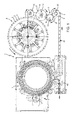
- numeral 1 indicates as a whole a container handling apparatus for performing a plurality of operations on containers made of a deformable material, in particular plastic bottles 2 ( Figures 1 , 2 and 4 to 7 ), so as to transform them in a final configuration ( Figure 7 ), in which they are filled with a pourable product, such as a non-carbonated liquid product, closed with respective caps 3 ( Figures 3 to 7 ) and labelled with respective labels 4 ( Figure 1 ).
- a container handling apparatus for performing a plurality of operations on containers made of a deformable material, in particular plastic bottles 2 ( Figures 1 , 2 and 4 to 7 ), so as to transform them in a final configuration ( Figure 7 ), in which they are filled with a pourable product, such as a non-carbonated liquid product, closed with respective caps 3 ( Figures 3 to 7 ) and labelled with respective labels 4 ( Figure 1 ).
- apparatus 1 comprises:
- each bottle 2 has a longitudinal axis A, a closed end or base 10 and an opposite open end 11 defined by a neck 12 for pouring the product contained in bottle 2.
- neck 12 of each bottle 2 has an outer thread and is adapted to receive a threaded cap 3.
- Bottles 2 are fed to filling machine 5 by an inlet star wheel conveyor 13 in an open condition and in a vertical position, i.e. with bases 10 arranged below respective necks 12.
- each bottle 2 is fed to filling machine 5 with its base 10 in the configuration of Figures 4 and 5 , hereafter denoted as "first configuration"; more specifically, in this configuration, base 10 has an annular area 15 having axis A, radially external and defining an annular resting surface of relative bottle 2, and a central slightly recessed area 16, surrounded by annular area 15 and arranged higher along axis A with respect to annular area 15 in a vertical position of bottle 2, i.e. with neck 12 placed above base 10; in other words, in the first configuration of base 10 of each bottle 2, central area 16 is arranged at a distance from neck 12 along axis A slightly smaller than the distance, along the same axis, between neck 12 and annular area 15.
- the bottles 2 may be fed to filling machine 5 in a configuration, in which their bases 10 are entirely plane.
- each bottle 2 After being filled with the pourable product at filling machine 5, each bottle 2 is fed in the vertical position to capping machine 6 by a star wheel conveyor 17; in this way, conveyor 17 operates as both an outlet conveyor for filling machine 5 and an inlet conveyor for capping machine 6.
- capping machine 6 basically comprises a carousel 18 mounted to rotate about a vertical central axis B.
- Carousel 18 receives a sequence of filled and open bottles 2 in the vertical positions from conveyor 17, which cooperates with the carousel 18 itself at a first transfer station 19; carousel 18 releases a sequence of capped bottles 2 in the vertical positions to an outlet conveyor 20, which cooperates with the carousel 18 itself at a second transfer station 21; carousel 18 also receives a sequence of caps 3 from a cap feeding device 22 (known per se and only partially shown in Figure 3 ), which cooperates with the carousel 18 itself at a third transfer station 23.
- a cap feeding device 22 known per se and only partially shown in Figure 3
- Carousel 18 comprises a plurality of operative units 24 (only one of which shown in detail in Figures 3 to 7 ), which are uniformly distributed about axis B and are mounted at a peripheral portion of carousel 18.
- Operative units 24 are displaced by carousel 18 along a circular processing path P which extends about axis B and through transfer sections 19, 21 and 23.
- transfer station 23 is preferably located upstream of transfer station 19, which is in turn arranged upstream of transfer station 21; in practice, transfer station 23 is arranged between transfer stations 19 and 21 with respect to processing path P.
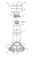
- each operative unit 24 has an axis C parallel to axis B and orthogonal to path P; each operative unit 24 basically comprises support means 25, carried by a rotating structure 26 of carousel 18 and adapted to support one bottle 2, and a capping head 27 also carried by the rotating structure 26 and selectively activated for applying one cap 3 onto the open end 11 of the relative bottle 2.
- support means 25 of operative unit 24 are adapted to receive a relative bottle 2 in the vertical position and with its base 10 in the first configuration ( Figure 4 ); support means 25 are also able to retain the bottle 2 in the above said position along path P from transfer station 19 to transfer station 21.
- Capping head 27 is in use located above bottle 2 and is movable to, and away from, the open end 11 of the bottle 2 to apply one cap 3 onto the open end 11 itself.
- capping head 27 has a top end portion 27a directly fixed to a bottom end 28a of a spindle 28, carried by rotating structure 26 of carousel 18 in a rotatable and translational manner with respect to axis C.
- spindle 28 is coaxial with axis C and is in use actuated with a movement of rotation about axis C and with a simultaneous movement of translation along the same axis C.
- the movements of rotation and translation are directly transmitted to capping head 27 and are coordinated with respect to one another so as to obtain a helical movement of spindle 28.
- the way in which such helical movement of spindle 28 is generated can be considered conventional and lies outside the scope of protection of the present invention.
- Capping head 27 also has a bottom end portion 30 provided with a seat 31 to house a relative cap 3 prior to applying it onto the relative bottle 2.
- seat 31 is defined by an axial threaded hole formed in bottom end portion 30 of capping head 27 and adapted to receive threaded cap 3.
- capping head 27 is displaced between a rest position ( Figure 7 ), in which it is detached from bottle 2, and a final application position ( Figure 6 ), in which it has completed application of cap 3 onto open end 11 of bottle 11.
- support means 25 comprise a support plate 32 fixed to a horizontal table 33 of rotating structure 26 of carousel 18 and adapted to define a horizontal support for base 10 of a relative bottle 2.
- support plate 32 is arranged above horizontal table 33, extends orthogonally to axis C and has, on top, a horizontal resting surface 34 for supporting base 10 of relative bottle 2.
- annular area 15 is the only part of bottle 2 contacting resting surface 34, being central area 16 retracted along axis A with respect to annular area 15.
- support plate 32 has a central through opening 35, arranged coaxial with axis C and with a respective through-hole 36 of table 33.
- Support means 25 also comprise gripping means 38 designed to act on the neck 12 of the relative bottle 2 so as to retain the bottle 2 itself in the vertical position on the support plate 32 during application of the relative cap 3.
- Operative unit 24 advantageously comprises a plunger 40 borne by table 33 of carousel 18 on the opposite side of support plate 32 with respect to bottle 2 and which is selectively displaceable along axis C, with respect to support plate 32, to act, through hole 36 and opening 35, on base 10 of relative bottle 2 and to deform it from the first configuration to a second configuration ( Figures 6 and 7 ) further-inwardly-retracted than the first configuration.
- central area 16 is more recessed with respect to annular area 15 than in the first configuration.
- base 10 of bottle 2 is in part further retracted inwardly of the bottle 2 itself with respect to the first configuration.
- the first configuration corresponds to a maximum internal volume of bottle 2
- the second configuration defines an internal volume of the bottle 2 itself smaller than that in the first configuration and an inner pressure higher than in the first configuration.
- plunger 40 is coaxial with axis A of the bottle 2 borne by support plate 32 and is selectively displaceable between a retracted position ( Figures 3 to 5 and 7 ), in which it is detached or spaced from base 10 of the bottle 2, and an advanced position ( Figure 6 ), in which it extends through hole 36 of table 33 as well as opening 35 of support plate 32 and has completed deformation of base 10 of the bottle 2 itself.
- plunger 40 is moved from the retracted position to the advanced position after capping head 27 has reached the final application position. As shown in Figure 6 , capping head 27 is maintained in the final application position while plunger 40 is moved from the retracted position to the advanced position.
- plunger 40 may be moved from the retracted position to the advanced position while capping head 27 is moved from the rest position to the final application position.
- plunger 40 is axially actuated by a fluidic actuator (known per se and not shown), for example of pneumatic type, carried by table 33.
- a fluidic actuator for example of pneumatic type
- plunger 40 may be coupled to, or be defined, by a linear motion mobile member or may be driven by an electric motor coupled with a worm screw.
- Bottles 2 exiting from carousel 18 of capping machine 6 are then transferred to labelling machine 7 directly by conveyor 20 only or by conveyor 20 in conjunction with a further linear conveyor 41, able to change the spacing between bottles 2, and with a final starwheel conveyor 42 directly cooperating with the labelling machine 7.
- Labelled bottles 2 exiting from labelling machine 7 are then transferred, by a starwheel conveyor 43, to a next processing machine (not shown).
- bottles 2 are filled on filling machine 5 with a pourable product at ambient temperature, for example a liquid food product at about 20°C.
- a pourable product at ambient temperature for example a liquid food product at about 20°C.
- empty bottles 2 are fed to filling machine 5 by conveyor 13 and, after being filled, exit filling machine 5 through conveyor 17. From here bottles 2 reach capping machine 6 to be closed with respective caps 3.
- bottles 2 are directly transferred to carousel 18 and reach in a sequence the different operative units 24 of the carousel 18 itself.
- Each bottle 2 is transferred to a relative operative unit 24 with its base 10 in the first configuration.
- Each bottle 2 is arranged resting on support plate 32 of the relative operating unit 24 and is retained on top by gripping means 38.
- bottles 2 are fed to carousel 18 in a vertical position, with their axes A parallel to central axis B and coaxial to axes C of respective operating units 24.
- each operative unit 24 Prior to reaching transfer station 19, each operative unit 24 receives a relative cap 3 at transfer station 23 by cap feeding device 22 ( Figure 3 ); in particular, the cap 3 is housed within seat 31 of bottom end portion 30 of a relative capping head 27.
- each capping head 27 is moved by the relative spindle 28 from the rest position to the final application position.
- the helical movement impressed by spindle 28 to capping head 27 produces screwing of cap 3 on neck 12 of bottle 2 ( Figures 4 and 5 ).
- capping head 27 is maintained in its final application position ( Figure 6 ) and the relative plunger 40 is activated to bring base 10 of bottle 2 from the first to the second configuration.
- the deforming operation on base 10 of each bottle 2 may be also performed simultaneously with the application of the cap 3 on the same bottle 2.
- movement of capping head 27 from the rest position to the final application position occurs at the same time with movement of the respective plunger 40 from the retracted position to the advanced position.
- each bottle 2 exiting therefrom has a reduced internal volume and an increased inner pressure. This produces a consequent "stiffening" of the lateral walls of bottles 2, which can therefore be more easily labelled than usual bottles.
- bottles 2 exiting from capping machine 6 and destined to be fed to labelling machine 7 by conveyors 41 and 42 have well-defined geometries and sufficiently rigid lateral surfaces to allow a correct application of labels 4.
- apparatus 1 has the same footprint as known apparatuses not performing deformation of the bottle bases.
- capping machine 6 as described and illustrated herein without, however, departing from the scope of protection as defined in the accompanying claims.
Landscapes
- Engineering & Computer Science (AREA)
- Mechanical Engineering (AREA)
- Filling Of Jars Or Cans And Processes For Cleaning And Sealing Jars (AREA)
- Sealing Of Jars (AREA)
Priority Applications (3)
| Application Number | Priority Date | Filing Date | Title |
|---|---|---|---|
| EP14174000.1A EP2960200A1 (de) | 2014-06-25 | 2014-06-25 | Verschliessmaschine |
| CN201510354584.7A CN105217547B (zh) | 2014-06-25 | 2015-06-24 | 一种用于对塑料瓶执行多个操作的容器处理装置 |
| US14/748,758 US9926180B2 (en) | 2014-06-25 | 2015-06-24 | Capping machine |
Applications Claiming Priority (1)
| Application Number | Priority Date | Filing Date | Title |
|---|---|---|---|
| EP14174000.1A EP2960200A1 (de) | 2014-06-25 | 2014-06-25 | Verschliessmaschine |
Publications (1)
| Publication Number | Publication Date |
|---|---|
| EP2960200A1 true EP2960200A1 (de) | 2015-12-30 |
Family
ID=50980995
Family Applications (1)
| Application Number | Title | Priority Date | Filing Date |
|---|---|---|---|
| EP14174000.1A Withdrawn EP2960200A1 (de) | 2014-06-25 | 2014-06-25 | Verschliessmaschine |
Country Status (3)
| Country | Link |
|---|---|
| US (1) | US9926180B2 (de) |
| EP (1) | EP2960200A1 (de) |
| CN (1) | CN105217547B (de) |
Cited By (2)
| Publication number | Priority date | Publication date | Assignee | Title |
|---|---|---|---|---|
| DE202015106723U1 (de) * | 2015-12-10 | 2017-03-13 | Krones Ag | Etikettiermaschine für Kunststoffbehälter |
| EP4403479A1 (de) * | 2022-01-14 | 2024-07-24 | Sidel Participations | Vorrichtung zum umstülpen eines behälterbodens |
Families Citing this family (2)
| Publication number | Priority date | Publication date | Assignee | Title |
|---|---|---|---|---|
| CN108821211A (zh) * | 2018-07-12 | 2018-11-16 | 合肥七小俊生物科技有限公司 | 一种提高上盖率的装置 |
| CN112374436B (zh) * | 2020-11-11 | 2022-09-16 | 余啊星 | 一种瓶装食品加工用瓶子固定装置 |
Citations (8)
| Publication number | Priority date | Publication date | Assignee | Title |
|---|---|---|---|---|
| DE1246520B (de) * | 1962-12-14 | 1967-08-03 | Metal Box Co Ltd | Vorrichtung zum Verschliessen eines Behaelters mit Waenden aus elastischem, luftundurchlaessigem Material |
| JP2001097486A (ja) * | 1999-09-27 | 2001-04-10 | Q P Corp | キャッピング容器の保持固定装置 |
| WO2007127337A2 (en) * | 2006-04-28 | 2007-11-08 | Co2 Pac Limited | Pressure reinforced plastic container and related method of processing a plastic container |
| JP2008162658A (ja) * | 2006-12-28 | 2008-07-17 | Toyo Seikan Kaisha Ltd | プラスチックボトルに内容液が充填された製品の製造方法及びその製造装置 |
| DE102008026244A1 (de) * | 2008-05-30 | 2009-12-03 | Krones Ag | Verfahren zum Befüllen von Kunststoffflaschen und Flaschenfüller für Kunststoffflaschen |
| US20090293436A1 (en) * | 2006-07-03 | 2009-12-03 | Hokkai Can Co., Ltd. | Method and Device for Producing Content Filling Bottle |
| JP2011006074A (ja) * | 2009-06-23 | 2011-01-13 | Toppan Printing Co Ltd | 液体用紙製容器 |
| WO2013139874A1 (en) * | 2012-03-20 | 2013-09-26 | Sidel S.P.A. Con Socio Unico | Labelling machine |
Family Cites Families (13)
| Publication number | Priority date | Publication date | Assignee | Title |
|---|---|---|---|---|
| DE2158961A1 (de) * | 1971-11-27 | 1973-05-30 | Elelmezesipari Tervezoe Vallal | Automatische mehrzweckverschliessmaschine fuer bauchige gefaesse, insbesondere fuer konservenglaeser |
| JPS5819535B2 (ja) * | 1979-04-16 | 1983-04-19 | 本州製紙株式会社 | 密封容器のシ−ル方法 |
| DE3219906A1 (de) * | 1982-05-27 | 1983-12-01 | Pirzer, Carl, 8402 Neutraubling | Etikettiermaschine |
| JPH0755717B2 (ja) * | 1988-12-27 | 1995-06-14 | 澁谷工業株式会社 | キャッパ |
| DE9006376U1 (de) * | 1990-06-06 | 1991-05-02 | Krones Ag Hermann Kronseder Maschinenfabrik, 93073 Neutraubling | Vorrichtung zum Zentrieren und Ausrichten von Gefäßen |
| JPH05193633A (ja) * | 1991-12-19 | 1993-08-03 | Shibuya Kogyo Co Ltd | 容器位置決め装置 |
| FR2713195B1 (fr) * | 1993-12-02 | 1996-01-12 | Serac Sa | Installation de conditionnement pour des récipients ayant une base présentant au moins un grand côté et un petit côté. |
| US5398485A (en) * | 1994-03-31 | 1995-03-21 | H & K Inc. | Bottle support mechanism for a capping machine |
| ATE466814T1 (de) * | 2000-08-08 | 2010-05-15 | Sidel Spa | Verschliesskopf mit linearmotorantrieb |
| WO2005012091A2 (en) * | 2003-07-30 | 2005-02-10 | Graham Packaging Company, L.P. | Container handling system |
| WO2007132767A1 (ja) * | 2006-05-15 | 2007-11-22 | Hokkai Can Co., Ltd. | 内容物充填ボトルの製造方法及びその装置 |
| US8627944B2 (en) * | 2008-07-23 | 2014-01-14 | Graham Packaging Company L.P. | System, apparatus, and method for conveying a plurality of containers |
| TR201904887T4 (tr) * | 2009-02-10 | 2019-05-21 | Plastipack Packaging Inc | bir plastik kabın basınçlandırılmasına yönelik bir yöntem ve sistem. |
-
2014
- 2014-06-25 EP EP14174000.1A patent/EP2960200A1/de not_active Withdrawn
-
2015
- 2015-06-24 US US14/748,758 patent/US9926180B2/en not_active Expired - Fee Related
- 2015-06-24 CN CN201510354584.7A patent/CN105217547B/zh not_active Expired - Fee Related
Patent Citations (8)
| Publication number | Priority date | Publication date | Assignee | Title |
|---|---|---|---|---|
| DE1246520B (de) * | 1962-12-14 | 1967-08-03 | Metal Box Co Ltd | Vorrichtung zum Verschliessen eines Behaelters mit Waenden aus elastischem, luftundurchlaessigem Material |
| JP2001097486A (ja) * | 1999-09-27 | 2001-04-10 | Q P Corp | キャッピング容器の保持固定装置 |
| WO2007127337A2 (en) * | 2006-04-28 | 2007-11-08 | Co2 Pac Limited | Pressure reinforced plastic container and related method of processing a plastic container |
| US20090293436A1 (en) * | 2006-07-03 | 2009-12-03 | Hokkai Can Co., Ltd. | Method and Device for Producing Content Filling Bottle |
| JP2008162658A (ja) * | 2006-12-28 | 2008-07-17 | Toyo Seikan Kaisha Ltd | プラスチックボトルに内容液が充填された製品の製造方法及びその製造装置 |
| DE102008026244A1 (de) * | 2008-05-30 | 2009-12-03 | Krones Ag | Verfahren zum Befüllen von Kunststoffflaschen und Flaschenfüller für Kunststoffflaschen |
| JP2011006074A (ja) * | 2009-06-23 | 2011-01-13 | Toppan Printing Co Ltd | 液体用紙製容器 |
| WO2013139874A1 (en) * | 2012-03-20 | 2013-09-26 | Sidel S.P.A. Con Socio Unico | Labelling machine |
Cited By (2)
| Publication number | Priority date | Publication date | Assignee | Title |
|---|---|---|---|---|
| DE202015106723U1 (de) * | 2015-12-10 | 2017-03-13 | Krones Ag | Etikettiermaschine für Kunststoffbehälter |
| EP4403479A1 (de) * | 2022-01-14 | 2024-07-24 | Sidel Participations | Vorrichtung zum umstülpen eines behälterbodens |
Also Published As
| Publication number | Publication date |
|---|---|
| US20150375979A1 (en) | 2015-12-31 |
| US9926180B2 (en) | 2018-03-27 |
| CN105217547A (zh) | 2016-01-06 |
| CN105217547B (zh) | 2020-01-21 |
Similar Documents
| Publication | Publication Date | Title |
|---|---|---|
| US9758361B2 (en) | Machine and a method for filling containers | |
| US9828130B2 (en) | Container handling machine and method | |
| US10017370B2 (en) | Machine and method for filling containers | |
| US20130019570A1 (en) | Apparatus and method for automatically forming and filling containers, in particular water bottles | |
| EP3199490B1 (de) | Behälterhandhabungsvorrichtung zum füllen und verschliessen von behältern | |
| US9926180B2 (en) | Capping machine | |
| US10407289B2 (en) | Machine for filling bottles, cans and like containers | |
| EP2828170B1 (de) | Etikettiermaschine | |
| CA3125255A1 (fr) | Line for preparing and filling bottles | |
| EP2851334B1 (de) | Behälterhandhabungsvorrichtung | |
| EP2990344B1 (de) | Behälterbehandlungsmaschine und -Verfahren | |
| US10040590B2 (en) | Container handling machine and method | |
| US10273135B2 (en) | Machine for filling containers | |
| CN107000879A (zh) | 用于形成容器的基部的成形设备 | |
| EP2325133B1 (de) | Behälterverschliessvorrichtung |
Legal Events
| Date | Code | Title | Description |
|---|---|---|---|
| PUAI | Public reference made under article 153(3) epc to a published international application that has entered the european phase |
Free format text: ORIGINAL CODE: 0009012 |
|
| AK | Designated contracting states |
Kind code of ref document: A1 Designated state(s): AL AT BE BG CH CY CZ DE DK EE ES FI FR GB GR HR HU IE IS IT LI LT LU LV MC MK MT NL NO PL PT RO RS SE SI SK SM TR |
|
| AX | Request for extension of the european patent |
Extension state: BA ME |
|
| 17P | Request for examination filed |
Effective date: 20160628 |
|
| RBV | Designated contracting states (corrected) |
Designated state(s): AL AT BE BG CH CY CZ DE DK EE ES FI FR GB GR HR HU IE IS IT LI LT LU LV MC MK MT NL NO PL PT RO RS SE SI SK SM TR |
|
| STAA | Information on the status of an ep patent application or granted ep patent |
Free format text: STATUS: EXAMINATION IS IN PROGRESS |
|
| 17Q | First examination report despatched |
Effective date: 20180409 |
|
| GRAP | Despatch of communication of intention to grant a patent |
Free format text: ORIGINAL CODE: EPIDOSNIGR1 |
|
| STAA | Information on the status of an ep patent application or granted ep patent |
Free format text: STATUS: GRANT OF PATENT IS INTENDED |
|
| RIC1 | Information provided on ipc code assigned before grant |
Ipc: B67C 3/22 20060101ALN20221104BHEP Ipc: B67B 3/28 20060101ALI20221104BHEP Ipc: B67B 3/20 20060101AFI20221104BHEP |
|
| INTG | Intention to grant announced |
Effective date: 20221121 |
|
| STAA | Information on the status of an ep patent application or granted ep patent |
Free format text: STATUS: THE APPLICATION IS DEEMED TO BE WITHDRAWN |
|
| 18D | Application deemed to be withdrawn |
Effective date: 20230404 |