EP2960324A2 - Verfahren zur herstellung von biogas in einem fermenter und vorrichtung zur durchführung des verfahrens - Google Patents
Verfahren zur herstellung von biogas in einem fermenter und vorrichtung zur durchführung des verfahrens Download PDFInfo
- Publication number
- EP2960324A2 EP2960324A2 EP15173480.3A EP15173480A EP2960324A2 EP 2960324 A2 EP2960324 A2 EP 2960324A2 EP 15173480 A EP15173480 A EP 15173480A EP 2960324 A2 EP2960324 A2 EP 2960324A2
- Authority
- EP
- European Patent Office
- Prior art keywords
- fermenter
- substrate
- segments
- flow tube
- flow
- Prior art date
- Legal status (The legal status is an assumption and is not a legal conclusion. Google has not performed a legal analysis and makes no representation as to the accuracy of the status listed.)
- Granted
Links
Images


Classifications
-
- C—CHEMISTRY; METALLURGY
- C12—BIOCHEMISTRY; BEER; SPIRITS; WINE; VINEGAR; MICROBIOLOGY; ENZYMOLOGY; MUTATION OR GENETIC ENGINEERING
- C12M—APPARATUS FOR ENZYMOLOGY OR MICROBIOLOGY; APPARATUS FOR CULTURING MICROORGANISMS FOR PRODUCING BIOMASS, FOR GROWING CELLS OR FOR OBTAINING FERMENTATION OR METABOLIC PRODUCTS, i.e. BIOREACTORS OR FERMENTERS
- C12M21/00—Bioreactors or fermenters specially adapted for specific uses
- C12M21/04—Bioreactors or fermenters specially adapted for specific uses for producing gas, e.g. biogas
-
- C—CHEMISTRY; METALLURGY
- C12—BIOCHEMISTRY; BEER; SPIRITS; WINE; VINEGAR; MICROBIOLOGY; ENZYMOLOGY; MUTATION OR GENETIC ENGINEERING
- C12M—APPARATUS FOR ENZYMOLOGY OR MICROBIOLOGY; APPARATUS FOR CULTURING MICROORGANISMS FOR PRODUCING BIOMASS, FOR GROWING CELLS OR FOR OBTAINING FERMENTATION OR METABOLIC PRODUCTS, i.e. BIOREACTORS OR FERMENTERS
- C12M23/00—Constructional details, e.g. recesses, hinges
- C12M23/02—Form or structure of the vessel
- C12M23/06—Tubular
-
- C—CHEMISTRY; METALLURGY
- C12—BIOCHEMISTRY; BEER; SPIRITS; WINE; VINEGAR; MICROBIOLOGY; ENZYMOLOGY; MUTATION OR GENETIC ENGINEERING
- C12M—APPARATUS FOR ENZYMOLOGY OR MICROBIOLOGY; APPARATUS FOR CULTURING MICROORGANISMS FOR PRODUCING BIOMASS, FOR GROWING CELLS OR FOR OBTAINING FERMENTATION OR METABOLIC PRODUCTS, i.e. BIOREACTORS OR FERMENTERS
- C12M23/00—Constructional details, e.g. recesses, hinges
- C12M23/40—Manifolds; Distribution pieces
-
- C—CHEMISTRY; METALLURGY
- C12—BIOCHEMISTRY; BEER; SPIRITS; WINE; VINEGAR; MICROBIOLOGY; ENZYMOLOGY; MUTATION OR GENETIC ENGINEERING
- C12M—APPARATUS FOR ENZYMOLOGY OR MICROBIOLOGY; APPARATUS FOR CULTURING MICROORGANISMS FOR PRODUCING BIOMASS, FOR GROWING CELLS OR FOR OBTAINING FERMENTATION OR METABOLIC PRODUCTS, i.e. BIOREACTORS OR FERMENTERS
- C12M23/00—Constructional details, e.g. recesses, hinges
- C12M23/44—Multiple separable units; Modules
-
- C—CHEMISTRY; METALLURGY
- C12—BIOCHEMISTRY; BEER; SPIRITS; WINE; VINEGAR; MICROBIOLOGY; ENZYMOLOGY; MUTATION OR GENETIC ENGINEERING
- C12M—APPARATUS FOR ENZYMOLOGY OR MICROBIOLOGY; APPARATUS FOR CULTURING MICROORGANISMS FOR PRODUCING BIOMASS, FOR GROWING CELLS OR FOR OBTAINING FERMENTATION OR METABOLIC PRODUCTS, i.e. BIOREACTORS OR FERMENTERS
- C12M29/00—Means for introduction, extraction or recirculation of materials, e.g. pumps
- C12M29/26—Conditioning fluids entering or exiting the reaction vessel
-
- C—CHEMISTRY; METALLURGY
- C12—BIOCHEMISTRY; BEER; SPIRITS; WINE; VINEGAR; MICROBIOLOGY; ENZYMOLOGY; MUTATION OR GENETIC ENGINEERING
- C12M—APPARATUS FOR ENZYMOLOGY OR MICROBIOLOGY; APPARATUS FOR CULTURING MICROORGANISMS FOR PRODUCING BIOMASS, FOR GROWING CELLS OR FOR OBTAINING FERMENTATION OR METABOLIC PRODUCTS, i.e. BIOREACTORS OR FERMENTERS
- C12M41/00—Means for regulation, monitoring, measurement or control, e.g. flow regulation
- C12M41/12—Means for regulation, monitoring, measurement or control, e.g. flow regulation of temperature
- C12M41/18—Heat exchange systems, e.g. heat jackets or outer envelopes
-
- Y—GENERAL TAGGING OF NEW TECHNOLOGICAL DEVELOPMENTS; GENERAL TAGGING OF CROSS-SECTIONAL TECHNOLOGIES SPANNING OVER SEVERAL SECTIONS OF THE IPC; TECHNICAL SUBJECTS COVERED BY FORMER USPC CROSS-REFERENCE ART COLLECTIONS [XRACs] AND DIGESTS
- Y02—TECHNOLOGIES OR APPLICATIONS FOR MITIGATION OR ADAPTATION AGAINST CLIMATE CHANGE
- Y02E—REDUCTION OF GREENHOUSE GAS [GHG] EMISSIONS, RELATED TO ENERGY GENERATION, TRANSMISSION OR DISTRIBUTION
- Y02E50/00—Technologies for the production of fuel of non-fossil origin
- Y02E50/30—Fuel from waste, e.g. synthetic alcohol or diesel
Definitions
- the invention relates to a method for producing biogas in a fermenter, having the features of the preamble of claim 1.
- the invention relates to an apparatus for carrying out the method with the features of the preamble of claim 9.
- biogas plants the essential part of which is a fermenter in which biogas, d. H. a mixture of predominantly methane and carbon dioxide obtained in anaerobic digestion from biomass.
- biogas d. H. a mixture of predominantly methane and carbon dioxide obtained in anaerobic digestion from biomass.
- manure, sewage sludge, green waste, cereals, maize silage, sugar beet and the like are usually used among other things. Due to its solid substance and long-chain cellulose structures, wood is one of the less preferred substrate components.
- the fermenter may according to the prior art have different designs. It can be cylindrical upright or square lying. Conventional fermenters are often cylindrically upright, insulated containers in which the substrate is constantly stirred and in which the same temperature and concentration of the reactants in the substrate prevail at each location. Also lying fermenters are used with square shape, in which the Substrate is also stirred and prevails at each point the same temperature.
- the first phase of the biogas production process is a biochemical reaction in which polymer substances are split into their individual building blocks with water retention.
- the subsequent fermentation takes place in several phases in which different bacterial groups are involved.
- the first bacterial phase is the so-called Acidogenese.
- the monomers previously formed in the hydrolysis are taken up by bacteria and further fermented to different organic acids and alcohols.
- acetogenesis certain acids are fermented by acetogenic bacteria to acetic acid.
- methanogenesis the acetic acid is finally converted to methane and carbon dioxide.
- the biogas produced in this process is cleaned and then converted into electricity and heat usually in a cogeneration plant or fed into the natural gas grid after a corresponding gas treatment.
- thermophilic process stages which operate at a temperature between about 25 ° and 40 ° C
- thermophilic process stages which operate at a temperature between 40 ° C and 55 ° C. Fermenters with thermophilic process stages usually have a higher biogas yield within a certain time unit. The thermophilic reaction is faster in comparison than the mesophilic reaction. On the other hand, the thermophilic fermentation process is less stable compared to the mesophilic reaction and the heat requirement for a thermophilic process flow is higher for non-optimally isolated fermenters. Thus, fermenters with mesophilic and thermophilic operation have different advantages. As is known from nature, long-chain energetic structures are never implemented in a single process step.
- the state-of-the-art fermenters have only a single process stage.
- the entire biochemical decomposition so the hydrolysis, and the biological microbacterial decomposition in actively stirred fermenters instead.
- This concurrent process involves considerable disadvantages with respect to the entire decomposition process.
- the substrate flows in countercurrent principle at least two reactor vessels, which are operated with two substrate screw conveyors. This considerably increases the maintenance and repair sensitivity.
- thermophilic mode of operation with the advantages of a mesophilic mode of operation in a fermenter.
- the invention proposes a method with the features of claim 1, wherein the substrate flows through between the two ends of the fermenter successively arranged fermenter segments or zones, in which the substrate is heated to different temperatures, so heated and / or cooled is that exist for the running in the respective length segment or segment processes good reaction conditions.
- a fermenter in the sense of the present invention comprises at least one individual flow tube, which can be tempered in sections.
- each flow tube comprises various sections, viewed over its length, which can be tempered individually or in groups.
- the method according to the invention initially has the advantage that it is possible to work both with a mesophilic and with a thermophilic temperature range during the flow through the substrate through the fermenter in one pass.
- the individual fermenter zones or segments, of which preferably at least two are present, are characterized, inter alia, by the fact that they reflect different temperature zones.
- the successive fermenter zones or segments thus correspond to process stages with corresponding process temperatures. If, for example, the heat requirement is higher in the context of a thermophilic process stage, the substrate is either less strongly cooled or heated as required in a fermenter segment during its flow through the fermenter, for example by means of an active process and temperature control. On an active Mixing of the substrate can be dispensed with in the context of the method according to the invention.
- a fundamental idea of the invention is to simulate the natural biochemical decomposition processes in their development and their growth and to slow down or accelerate the individual phases of the microbacterial processes by targeted measures, in particular in order to promote the sub-processes during fermentation by suitable temperature.
- the temperature is varied segmentally or in sections from the outside and / or inside the fermenter.
- the entire biochemical decomposition preferably takes place according to the invention in exactly one horizontal flow tube which forms the fermenter.
- the fermenter or its flow tube is simplified to imagine as an elongated vessel with a cylindrical cross-section or similar shape, such as polygonal or conically widening shape.
- Decisive feature of the invention is that it is a continuous process with input, passage of several decomposition phases and output. According to the invention, it is provided that the substrate undergoes several microbacterial phases within the continuously running process.
- the phases include both mesophilic and thermophilic bacterial temperature ranges. The different temperature ranges that are the result of natural microbial decomposition processes are specifically supported by the method according to the invention.
- a mechanical mixing which is carried out for example by means of paddle stirrers, provided in the customary fermenters, generates locally high flow velocities in the substrate and the associated shear stresses have negative effects on the natural biochemical decomposition processes.
- the process of the present invention which avoids heavy mixing or even any form of motor-driven mixers, supports the biochemical decomposition processes much more optimally and more naturally.
- a sliding movement is provided, similar to the principle of peristalsis, which in particular by static, flow-conducting elements which are mounted inside the reactor, can be brought about. Consequently, the reaction mass within the flow tube is placed in a kind of helical movement and additionally directed from the outer edge of the fermenter to the central axis of the fermenter. This promotes the radial temperature compensation inside the fermenter and supports the desired axial temperature gradient.
- a tempering device which can heat or cool the segments selectively in the axial direction of the fermenter. This can be done in the continuous process in the fermenter - u.a. Depending on the composition of the substrate as well as on the outside temperature - the microbacterial processes can be selectively braked or accelerated. Thus, in detail, i.a. avoid that the thermophilic microbacterial phase is not running hot and that the mesophilic microbacterial phase accelerates in the individual phases of the continuous process in the fermenter.
- Another energetically advantageous advantage of using a zone-operating temperature control is that the released process heat of the natural decomposition processes, which is obtained by targeted and procedurally required cooling of the thermophilic areas in the fermenter, can be reused, even in the process, namely u.a. for preheating the mesophilic areas at the beginning of the fermenter.
- the bacterial growth within the fermenter takes place depending on the continuous process. It can be provided that a bacterial feedback is performed, but only specifically in individual areas of the fermentation. This bacterial feedback is characterized in that the bacteria are fed back into other zones or segments depending on the temperature and thus of the position in the fermenter.
- a temperature-controlled bacteria feedback is provided. This allows mesophilic bacteria to be returned to mesophilic fermenter areas and thermophilic bacteria to be returned to thermophilic fermenter areas to be led back. According to the invention it is preferably provided that the bacteria are fed back in front of a static guide baffle.
- the fermenter segments through which the substrate flows may be used as heat exchangers, e.g. operated according to the countercurrent principle, be formed.
- the fermenter may have a length of 75 meters and five segments, each 15 meters in length.
- the five segments represent different process stages that can operate at different process temperatures.
- a mesophilic mode of operation is initiated by the temperature of the substrate is controlled by means of the heat exchanger function of the fermenter segment targeted.
- the substrate temperature is controlled so that the thermophilic phase is introduced. Due to the resulting heat of reaction in the fermenter is specifically cooled by means of the heat exchanger of the individual fermenter segments and the associated process temperature control of the fermenter.
- the substrate during its conveyance by displacement through the fermenter, preferably undergoes a mesophilic as well as a thermophilic phase, preferably in an unstirred form, preferably with static flow-forming elements. Due to the different processes of hydrolysis and fermentation, d. H. due to biochemical and microbacterial processes, i.a. Both at different process temperatures and in different pH values, the hydrolysis phase is carried out in advance separately. Furthermore, without upstream hydrolysis phase, the microbial conversion of the substrate component wood would take a long time due to their structures of long cellulose chains.
- wood can thus be processed economically as a substrate component.
- the substrate flows through a flow tube which is subdivided into segments with different lengths and / or with different diameters. Different lengths can be used to set different residence times in a specific temperature zone and thus different reaction times.
- the local cooling rate can be influenced via the outer diameter of a segment, in particular if a temperature control via irrigation of the outer shell of the segment is provided. Changes in the segment diameter can thus have an effect on the process temperature and thus also initiate both a mesophilic and a thermophilic process within the fermenter.
- the substrate flows through segments of identical length and identical cross section or segments of identical length and different cross section or diameter.
- the fermenters can have an increasing cross-section in the direction of the substrate outlet and, for example, assume a conical, pyramidal or cylindrical shape.
- hydrolysis is a (bio-) chemical reaction which can be described according to the Arrhenius equation, according to which an increasing temperature is accompanied by an increase in the reaction rate.
- Optimal and rapid hydrolysis occurs at temperatures of e.g. 105 ° C far above mesophilic and thermophilic processes.
- a thermophilic bacterial reaction takes place below and up to a temperature range of 55 ° C maximum.
- the process according to the invention can thus be used with particular preference in the context of a multistage plant in which the hydrolysis phase takes place in a separate process and precedes the process according to the invention.
- the reaction conditions of the phases differ significantly; the hydrolysis phase preferably takes place in a slightly acidic environment, for example at a pH 4-5; the bacterial fermentation process preferably takes place under slightly alkaline conditions (pH 7 - 8). Against this background, it makes sense to decouple the processes of hydrolysis and microbacterial fermentation spatially. However, a residual hydrolysis of the substrate will also take place in the fermenter according to the invention, but this is irrelevant.
- An apparatus for carrying out the method is the subject matter of claim 9, wherein the apparatus comprises a fermenter which is temperature-controlled in sections and in particular subdivided into segments which can be tempered in certain areas or to which a respective heat exchanger is assigned.
- the segments can be designed, for example, as a double-walled tube, which may be located in the space between the walls another medium for the heat exchange.
- the device according to the invention dispenses with mechanical agitators, screw transport devices or paddle agitators in the interior of the fermenter. According to the intent to recreate the natural decomposition processes, there are no mechanically driven components inside the fermenter.
- An active, process-controlled temperature control device for partial cooling or heating of the fermenter tube is preferably carried out as a spraying or sprinkling system. Water or another suitable liquid is sprayed from the outside onto the outer casing of the flow tube or its individual segments.
- a practicable variant of the invention provides that the fermenter is designed as a segmented plug-flow fermenter which is biologically and mechanically reliable due to the stable plug flow.
- the segments of the fermenter can be modules that are easy to connect to each other, so that the fermenter has a modular design and thus can be relatively easily transported and assembled on site.
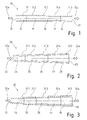
- the inventive method can be based on a in Fig. 1 in a lateral sectional view shown lying fermenter 10, which in the in Fig. 1 illustrated embodiment in the form of a Pfropfenstromfermenters present.
- the fermenter 10 has a length of 75 m and consists of a flow tube, which is divided into a plurality of segments 14, 15, 16, 17, 18, which are arranged directly one behind the other.
- the length of each segment 14, 15, 16, 17, 18 is 15 m.
- At the in Fig. 1 illustrated embodiment of the fermenter 10 are the segments 14, 15, 16, 17, 18 in the form of releasably interconnected modules, so that the fermenter 10 can be disassembled into the segments 14, 15, 16, 17, 18.
- Each segment 14, 15, 16, 17, 18 is assigned by the double-walled construction of the segments 14, 15, 16, 17, 18 each have a heat exchanger 11.1, 11.2, 11.3, 11.4, 11.5 with a heat exchanger function. Between the inner and outer segment walls, the heat exchange medium is at a heat exchanger medium temperature. At the in Fig. 1 shown embodiment of the method is carried out in the conventional countercurrent process.
- the process begins by charging the fermentor 10 such that substrate at the inlet 12 of the fermenter 10 is placed in the interior of the fermenter 10 in a conventional manner. Due to the relatively high solids content of the substrate, for. B. 20 - 30%, flows through the substrate in the flow direction 12a, the fermenter 10 in the form of a relatively stable mass according to the plug flow method and is performed at the outlet 13 of the fermenter 10 as a treated substrate in a conventional manner from the fermenter 10. The transport of the substrate in the fermenter 10 is done by displacement by means of input of the fresh material into the fermenter 10. The substrate in the fermenter 10 remains substantially in an unmoved state. Static flow forming elements in the fermentor 10 may carry the substrate transport.
- the substrate has passed through the individual segments 14, 15, 16, 17, 18 in the flow direction 12a and thereby has three stages of microbial production of biogas, i. H. Acidogenesis, acetogenesis and methanogenesis.
- the biogas produced in this case collects in the upper region of the individual segments 14, 15, 16, 17, 18 and is selectively removed from the fermenter 10 from each segment 14, 15, 16, 17, 18 or at the end of the segment 18 at the outlet 13 ,
- a process for the production of biogas with a suitable fermenter is involved in a multi-stage process, ie the first stage of the biogas production process, the hydrolysis, does not take place in the fermenter 10 or only to a small extent as residual hydrolysis.
- the substrate introduced into the fermenter 10 is therefore predominantly hydrolyzed substrate.
- the in Fig. 1 shown fermenter 10 is a fermenter, which is the hydrolysis as a purely chemical or enzymatic and biochemical process spatially downstream and take place in the overwhelming majority of only the bacterial conversion processes of acidogenesis, acetogenesis and methanogenesis, their rate of activity and growth rate of the corresponding bacteria are coupled.
- thermophilic bacteria In terms of microbial production of biogas, this means that most mesophilic bacterial species reach their maximum activity and growth rate in a range between 25 ° C and 40 ° C.
- the reaction rate of thermophilic bacteria begins only at temperatures above 40 ° C.
- the substrate introduced into the fermenter 10 in the individual segments 14, 15, 16, 17, 18 during the flow through the substrate in the flow direction 12a through the segments 14, 15, 16, 17, 18 by means of targeted cooling or heating to mesophilic and thermophilic Process temperatures brought.
- the onset of fermentation in the fermenter 10 is accompanied by the generation of heat of reaction.
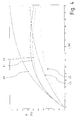
- the course of the reaction heat is shown in the graph in Fig. 4 out.
- the substrate contains about 1/3 hydrolyzed wood as well as green waste, manure and manure. Specifically, wood with its long-chain cellulose structures must be hydrolyzed mainly before fermentation in a separate upstream process.
- Fig. 4 shows the temperature development of the introduced into the fermenter 10 fermentation substrate as a function of the length of the fermenter 10.
- fermenter 10 has a length of 75 m and the segments 14, 15, 16, 17, 18 each have a length of 15 m.
- the total throughput time in the present case is about 30 days, ie a substrate throughput speed of about 2.5 m / day.
- the freshly introduced and heated substrate in the fermenter 10 like the temperature graph 40 in FIG Fig. 4 clarifies, due to released process heat after a relatively short residence time of approx.
- the process temperature of the substrate rises relatively quickly despite cooling over a range of approx. 55 ° C.
- it is cooled in segment 15 with a heat exchanger medium temperature of 22.5 ° C. and in segment 16 with a heat exchanger medium temperature of 25 ° C.
- the temperature graph 41 in Fig. 4 shows the temperature profile of the substrate in the flow direction 12a in the middle of the longitudinal axis of the fermenter 10.
- the temperature graph 42 in Fig. 40 shows the temperature profile of the substrate in the flow direction 12a, and at a distance of 0.5 m from the center of the longitudinal axis of the fermenter 10 away.
- the substrate flowing through the fermenter 10 leaves the fermenter 10 at the outlet 13 with the lowest possible temperature.
- the energy released here, generated from the heat of reaction, can be used for example for the spatially and temporally upstream hydrolysis.
- the last two segments 17 and 18 are again cooled with lower heat exchanger medium temperature, eg 22.5 ° C for segment 17 and 20 ° C for segment 18.
- the substrate temperature in segments 17 and 18, ie in the range between 45 m and 75 m decreases.
- the comparison between the temperature graphs 41 and 42 also shows that there is a temperature gradient in the radial direction in the fermenter, due in part to the unstirred shape of the substrate.
- the radial temperature gradient in the fermenter 10 promotes the partial formation of bacterial cultures and thus supports the transitions of the individual mesophilic and thermophilic process phases and thus promotes the corresponding fermentation of the substrate.
- FIGS. 2 and 3 show further geometric embodiments of a plug-flow fermenter 10 which can be used for the method according to the invention.
- the in the FIGS. 2 and 3 shown fermenters which are provided with the reference numerals 20 and 30, also have segments 24, 25, 26, 27, 28 and 34, 35, 36, 37, 38, which in turn each tempering such as heat exchangers 21.1, 21.2, 21.3, 21.4, 21.5 and 31.1, 31.2, 31.3, 31.4, 31.5 by means of double-walled construction the segments 24, 25, 26, 27, 28 and 34, 35, 36, 37, 38 are assigned.
- At the two ends of the fermenter 20 and 30 are also also inputs and outlets, which are identified by the reference numerals 22, 23 and 32, 33.
- At the inlets 22 and 32 substrate in the flow direction 22a and 32a is fed to the fermenters 20 and 30 and discharged at the outlets 23 and 33, the substrate treated in the fermenters 20 and 30 again.
- the diameter of the segments 24, 25, 26, 27, 28 of the fermenter 20 and the segments 34, 35, 36, 37, 38 of the fermenter 30 increases in the direction of the outlets 23 and 33 at.
- An increasing cross-section or diameter of 1.5 m at the beginning of the first segment to 2.5 m at the end of the last segment proves to be advantageous for process temperature control and general process flow.
- diameter changes of 0.25 m on the basis of the analyzes and simulations prove to be expedient for an economic and smooth process flow.
- the next temperature graphs 43 and 44 assume segment diameters of successively 1.5 m, 1.75 m, 2.0 m, 2.25 m and 2.5 m, as used in the fermenter 30 in FIG Fig. 3 are implemented.
- the geometric shapes of the fermenter 30, like the temperature graphs 43 and 44 in FIG Fig. 4 show, effects on the course of the process temperatures in the individual segments 34, 35, 36, 37 and 38 of the fermenter 30. It is always by appropriate cooling means of the heat exchangers 31.1, 31.2, 31.3, 31.4 and 31.5 of the double-walled segments 34, 35, 36, 37 and 38 of the fermenter reaches 30 mesophilic and thermophilic process stages, these process temperatures, especially in the first half of the fermenter 30 lower than that in Fig. 1 shown fermenter 10 are. As can also be seen from the temperature graphs 43 and 44, the radial temperature gradient of the substrate in fermenter 30 becomes greater than in fermenter 10.
- the temperature graph 43 in Fig. 4 shows the temperature profile of the substrate in the flow direction 32a in the middle of the longitudinal axis of the fermenter 30th
- the temperature graph 44 in Fig. 4 shows the temperature profile of the substrate in the flow direction 32a at a distance of 0.5 m at the beginning of the fermenter 30 to 0.75 m at the end of the fermenter 30 from the center of the longitudinal axis of the fermenter 30 seen from.
- the present invention is not limited in its execution to those indicated above. Rather, a variety of variants is conceivable, which make use of the illustrated solution even with fundamentally different types of execution. For example, during the treatment of the substrate in fermenters with altered geometries by means of described sequential heat exchanger functions and a corresponding dynamic process temperature control, further different temperature profiles that fulfill mesophilic and thermophilic processes can be generated.
- FIG. 2 shows a longitudinal section of a fermenter 56 without a temperature control device, which extends between a fermenter inlet 51 and a fermenter outlet 52.
- the temperature-controlled bacteria inlet and outlet lines 54, 55 can be mounted as often as desired, depending on the substrate composition and the length L of the fermenter 56,
- a guide baffle 53 displaces the reaction mass into an axial and rotating motion and additionally directs it from the edge of the fermenter to the central axis of the fermenter.
- the fermenter 56 is shown in cross-section and the temperature control device provided in the preferred embodiment.
- the tempering device does not take the form of a heat exchanger integrated in the wall of the flow tube, but the entire fermenter is placed under a cover 58.
- a spray device 57 Above the flow tube 56 is a spray device 57, which is designed for example as a pipe sprinkler.
- the flow tube 56 is raised above fastening means 61 above a collecting basin 59.
- the fermenter be tempered continuously by simply its wall is wetted from above with more or less tempering water 60.
- the temperature control can be carried out in a targeted manner in corresponding segments of the fermenter 56. This allows the individual microbacterial phases to be specifically tempered in the continuously running process.
Landscapes
- Health & Medical Sciences (AREA)
- Life Sciences & Earth Sciences (AREA)
- Chemical & Material Sciences (AREA)
- Engineering & Computer Science (AREA)
- Wood Science & Technology (AREA)
- Organic Chemistry (AREA)
- Bioinformatics & Cheminformatics (AREA)
- Zoology (AREA)
- Genetics & Genomics (AREA)
- Biochemistry (AREA)
- Sustainable Development (AREA)
- Microbiology (AREA)
- Biotechnology (AREA)
- General Engineering & Computer Science (AREA)
- General Health & Medical Sciences (AREA)
- Biomedical Technology (AREA)
- Clinical Laboratory Science (AREA)
- Molecular Biology (AREA)
- Physics & Mathematics (AREA)
- Thermal Sciences (AREA)
- Analytical Chemistry (AREA)
- General Chemical & Material Sciences (AREA)
- Oil, Petroleum & Natural Gas (AREA)
- Processing Of Solid Wastes (AREA)
- Apparatus Associated With Microorganisms And Enzymes (AREA)
Description
- Die Erfindung betrifft ein Verfahren zur Herstellung von Biogas in einem Fermenter, mit den Merkmalen des Oberbegriffs des Anspruchs 1. Zudem betrifft die Erfindung eine Vorrichtung zur Durchführung des Verfahrens mit den Merkmalen des Oberbegriffs des Anspruchs 9.
- Verfahren der eingangs genannten Art sind aus dem Stand der Technik bekannt und werden in Biogasanlagen durchgeführt, deren wesentlicher Bestandteil ein Fermenter ist, in dem Biogas, d. h. ein Gemisch aus vorwiegend Methan und Kohlenstoffdioxid, in einer anaeroben Vergärung aus Biomasse gewonnen wird. Als Gärsubstrate werden gewöhnlich unter anderem Gülle, Klärschlamm, Grünabfälle, Getreide, Maissilage, Zuckerrüben und dergleichen eingesetzt. Holz gehört aufgrund seiner festen Substanz und langkettigen Zellulose-Strukturen bisher zu den weniger bevorzugten Substratkomponenten.
- Der Fermenter kann gemäß dem Stand der Technik verschiedene Bauformen aufweisen. Er kann zylindrisch aufrecht oder quadratisch liegend sein. Herkömmliche Fermenter sind häufig zylindrisch aufrecht stehende, isolierte Behälter, in denen das Substrat ständig gerührt wird und in denen an jeder Stelle die gleiche Temperatur und die gleiche Konzentration der Umsetzungsstoffe in dem Substrat vorherrschen. Auch werden liegende Fermenter mit quadratischer Form eingesetzt, in denen das Substrat ebenfalls gerührt wird und an jeder Stelle die gleiche Temperatur vorherrscht.
- Die erste Phase des Biogasgewinnungsprozesses, die Hydrolyse, ist eine biochemische Umsetzung, in der polymere Substanzen unter Wassereinlagerung in ihre Einzelbausteine gespalten werden. Die anschließende Vergärung vollzieht sich in mehreren Phasen, an denen unterschiedliche Bakteriengruppen beteiligt sind. Die erste bakterielle Phase stellt die sogenannte Acidogenese dar. In dieser Phase werden die zuvor in der Hydrolyse gebildeten Monomere von Bakterien aufgenommen und zu unterschiedlichen organischen Säuren und Alkoholen weiter vergoren. In einer sich anschließenden Phase, in der sogenannten Acetogenese, werden bestimmte Säuren von acetogenen Bakterien zu Essigsäure vergoren. In der finalen Phase, in der Methanogenese, wird die Essigsäure schließlich zu Methan und Kohlenstoffdioxid umgesetzt. Das hierbei erzeugte Biogas wird gereinigt und anschließend in der Regel in einem Blockheizkraftwerk in Strom und Wärme umgewandelt oder nach einer entsprechenden Gasaufbereitung ins Erdgasnetz eingespeist.
- Bei der Biogasvergärung wird unter anderem zwischen mesophilen Prozessstufen, die bei einer Temperatur zwischen ca.25° und 40° C arbeiten, und thermophilen Prozessstufen, die bei einer Temperatur zwischen 40° C und 55 ° C arbeiten, unterschieden. Fermenter mit thermophilen Prozessstufen haben in der Regel innerhalb einer bestimmten Zeiteinheit eine höhere Biogasausbeute. Die thermophile Umsetzung ist im Vergleich schneller als die mesophile Umsetzung. Andererseits ist der thermophile Vergärungsprozess im Vergleich zur mesophilen Umsetzung weniger stabil und bei nicht optimal isolierten Fermentern der Wärmebedarf für einen stabilen thermophilen Prozessablauf höher. Somit weisen Fermenter mit mesophiler und thermophiler Betriebsweise unterschiedliche Vorteile auf. Wie aus der Natur bekannt ist, werden langkettige energetische Strukturen niemals in nur einem einzelnen Prozessschritt umgesetzt. Jedoch bleibt festzustellen, dass die Fermenter nach aktuellen Stand der Technik nur über eine einzelne Prozessstufe verfügen. Bei der in der
DE 10 2008 038 065 A1 beschrieben Anlage zur Biogasgewinnung findet die gesamte biochemische Zersetzung, also die Hydrolyse, und die biologische mikrobakterielle Zersetzung in aktiv gerührten Fermentern statt. Dieser gleichzeitige Ablauf bringt erhebliche Nachteile bezüglich des gesamten Zersetzungsprozesses mit sich. Außerdem durchströmt das Substrat im Gegenstrom Prinzip mindestens zwei Reaktorbehälter, welche mit zwei Substrat-Förderschneckentransportvorrichtungen betrieben werden. Dies erhöht die Wartungs- und Reparaturempfindlichkeit erheblich. - Es ist deshalb Aufgabe der vorliegenden Erfindung, ein Verfahren der eingangs genannten Art zur Verfügung zu stellen, das die Vorteile einer thermophilen Betriebsweise mit den Vorteilen einer mesophilen Betriebsweise in einem Fermenter vereint.
- Zur Lösung dieser Aufgabe schlägt die Erfindung ein Verfahren mit den Merkmalen des Anspruchs 1 vor, bei dem das Substrat zwischen den beiden Enden des Fermenters hintereinander angeordnete Fermentersegmente oder -zonen durchströmt, in denen das Substrat unterschiedlich temperiert wird, also so erwärmt und/oder abgekühlt wird, dass für die in dem jeweiligen Längenabschnitt oder Segment ablaufenden Prozesse gute Reaktionsbedingungen bestehen.
- Ein Fermenter im Sinne der vorliegenden Erfindung umfasst wenigstens ein einzelnes Strömungsrohr, das abschnittsweise temperierbar ist.
- Erfindungsgemäß ist insbesondere vorgesehen, dass das Strömungsrohr abschnittsweise in Segmente unterteilt ist. Zwar können auch mehrere solcher segmentierten Strömungsrohre parallel betrieben werden, jedoch ist wichtig, dass jedes Strömungsrohr für sich über die Länge gesehen verschiedene Abschnitte umfasst, die einzeln oder gruppenweise temperierbar sind.
- Das erfindungsgemäße Verfahren hat zunächst den Vorteil, dass während der Durchströmung des Substrats durch den Fermenter in einem Durchlauf sowohl mit einem mesophilen als auch mit einem thermophilen Temperaturbereich gearbeitet werden kann. Die einzelnen Fermenterzonen oder -segmente, von denen vorzugsweise mindestens zwei vorhanden sind, zeichnen sich unter anderem dadurch aus, dass sie unterschiedliche Temperaturzonen widerspiegeln.
- Die hintereinander angeordneten Fermenterzonen oder - segmente entsprechen somit Prozessstufen mit entsprechenden Prozesstemperaturen. Ist beispielsweise im Rahmen einer thermophilen Prozessstufe der Wärmebedarf höher, wird in einem hierfür vorgesehenen Fermentersegment das Substrat während seiner Durchströmung durch den Fermenter entweder weniger stark gekühlt oder je nach Bedarf erwärmt, z.B. mittels einer aktiven Prozess- und Temperatursteuerung. Auf eine aktive Durchmischung des Substrats kann im Rahmen des erfindungsgemäßen Verfahrens verzichtet werden.
- Eine grundlegende Idee der Erfindung ist es, die natürlichen biochemischen Zersetzungs-prozesse in ihrer Entwicklung und ihrem Wachstum nachzuempfinden und die einzelnen Phasen der mikrobakteriellen Prozesse durch gezielte Maßnahmen zu bremsen oder zu beschleunigen, insbesondere um durch geeignete Temperatur die Teilprozesse bei der Vergärung zu fördern.
- Um also entlang der Fermenterlänge sowohl eine mesophile als auch eine thermophile Betriebsweise zu realisieren, wird von außen und/oder innerhalb des Fermenters segment- oder streckenweise die Temperatur variiert.
- Die gesamte biochemische Zersetzung findet erfindungsgemäß bevorzugt in genau einem liegenden Strömungsrohr statt, das den Fermenter bildet. Der Fermenter bzw. sein Strömungsrohr ist vereinfacht vorzustellen wie ein längliches Gefäß mit zylindrischem Querschnitt oder ähnlicher Form, z.B. vieleckig oder konisch größer werdender Form.
- Entscheidendes Merkmal der Erfindung ist, dass es sich um einen kontinuierlich ablaufenden Prozess mit Eingang, Durchlauf mehrerer Zersetzungsphasen und Ausgang handelt. Erfindungsgemäß ist vorgesehen, dass das Substrat innerhalb des kontinuierlich verlaufenden Prozesses mehrere mikrobakterielle Phasen durchläuft. Die Phasen beinhalten sowohl mesophile als auch thermophile bakteriellen Temperaturbereiche. Die unterschiedlichen Temperaturbereiche, die Resultat natürlicher mikrobakteriellen Zersetzungsprozesse sind, werden durch das erfindungsgemäße Verfahren gezielt unterstützt.
- Eine in den marktüblichen Fermentern vorgesehene mechanische Durchmischung, die zum Beispiel mittels Paddel-Rührwerken erfolgt, erzeugt lokal hohe Strömungsgeschwindigkeiten im Substrat und die damit verbundenen Scherspannungen haben negative Auswirkungen auf die natürlichen biochemischen Zersetzungsprozesse. Entgegen der üblichen Praxis mit gerührten Fermentern werden mit dem erfindungsgemäßen Verfahren, das eine starke Durchmischung oder sogar jede Form von motorisch angetriebenen Mischern vermeidet, die biochemischen Zersetzungsprozesse sehr viel optimaler und natürlicher unterstützt.
- Demnach ist nach der Erfindung vorzugsweise für die Durchmischung des Substrates eine gleitende Bewegung vorgesehen, ähnlich dem Prinzip der Peristaltik, welche insbesondere durch statische, strömungsleitende Elemente, die im Inneren des Reaktors angebracht werden, herbeigeführt werden kann. Folglich wird die Reaktionsmasse innerhalb des Strömungsrohrs in eine Art schraubenförmige Bewegung versetzt und zusätzlich vom äußeren Rand des Fermenters zur Mittelachse des Fermenters gelenkt. Dies fördert den radialen Temperaturausgleich im Inneren des Fermenters und unterstützt das gewünschte axiale Temperaturgefälle.
- Zur Steuerung der natürlichen Zersetzungsprozesse ist vorzugsweise eine Temperiervorrichtung vorgesehen, die in axialer Richtung des Fermenters die Segmente streckenweise gezielt erwärmen oder kühlen kann. Damit können im kontinuierlich verlaufenden Prozess im Fermenter - u.a. in Abhängigkeit der Zusammensetzung des Substrates sowie von der Außentemperatur - die mikrobakteriellen Prozesse streckenweise gezielt gebremst oder beschleunigt werden. Damit kann im Einzelnen u.a. vermieden werden, dass die thermophile mikrobakterielle Phase nicht heiß läuft und dass die mesophile mikrobakterielle Phase in den einzelnen Phasen des kontinuierlichen Ablaufs im Fermenter beschleunigt anläuft. Ein weiterer energetisch wirtschaftlicher Vorteil der Verwendung einer zonenweise arbeitenden Temperiervorrichtung ist, dass die freiwerdende Prozesswärme der natürlichen Zersetzungsprozesse, die durch gezielte und prozesstechnisch erforderliche Kühlung der thermophilen Bereiche im Fermenter gewonnen wird, wiederverwendet werden kann, auch direkt im Prozess, nämlich u.a. für Vorerwärmung der mesophilen Bereiche am Anfang des Fermenters.
- Das bakterielle Wachstum innerhalb des Fermenters findet in Abhängigkeit des kontinuierlich ablaufenden Prozesses statt. Es kann vorgesehen sein, dass eine Bakterien-Rückkoppelung durchgeführt wird, jedoch nur gezielt in einzelnen Bereichen des Fermentes. Diese Bakterien-Rückkoppelung ist dadurch gekennzeichnet, dass die Bakterien abhängig von der Temperatur und somit von der Position im Fermenter in andere Zonen oder Segmente zurückgekoppelt werden.
- Erfindungsgemäß ist eine temperaturgesteuerte Bakterien-Rückkoppelung vorgesehen. Damit können mesophile Bakterien wieder in mesophile Fermenterbereiche rückgeführt und thermophile Bakterien wieder in thermophile Fermenterbereiche zurückgeführt werden. Erfindungsgemäß ist bevorzugt vorgesehen, dass die Bakterien vor einem statischen Führungsleitblech rückgekoppelt werden.
- Die Fermentersegmente, durch die das Substrat strömt, können als Wärmetauscher, z.B. nach dem Gegenstromprinzip betrieben, ausgebildet sein.
- Beispielsweise kann der Fermenter eine Länge von 75 m und fünf Segmente aufweisen, die wiederum jeweils 15 m lang sind. Die fünf Segmente stellen verschiedene Prozessstufen dar, die mit verschiedenen Prozesstemperaturen arbeiten können. Im Rahmen einer ersten Prozessstufe, in dem ersten Segment, wird dabei beispielsweise eine mesophile Betriebsweise eingeleitet, indem die Temperatur des Substrats mittels der Wärmetauscherfunktion des Fermentersegments gezielt gesteuert wird. In den darauf folgenden zwei Prozessstufen, d. h. im zweiten und dritten Segment, und ab einer Fermenterlänge von 15 m bis zu einer Fermenterlänge von 45 m wird die Substrattemperatur derart geregelt, dass die thermophile Phase eingeleitet wird. Durch die entstehende Reaktionswärme im Fermenter wird mittels der Wärmetauscher der einzelnen Fermentersegmente und der damit dazugehörigen Prozesstemperatursteuerung des Fermenters gezielt gekühlt.
- Das Substrat durchläuft während seiner Beförderung mittels Verdrängung durch den Fermenter vorzugsweise in ungerührter Form, bevorzugt mit statischen strömungsbildenden Elementen, eine mesophile als auch eine thermophile Phase. Aufgrund der unterschiedlichen Prozesse der Hydrolyse und Vergärung, d. h. aufgrund von biochemischen und mikrobakteriellen Prozessen, welche sich u.a. sowohl in unterschiedlichen Prozesstemperaturen als auch in unterschiedlichen pH-Werten widerspiegeln, wird die Hydrolyse-Phase vorab getrennt durchgeführt. Des Weiteren würde ohne vorgeschaltete Hydrolyse-Phase die mikrobakterielle Umsetzung der Substratkomponente Holz aufgrund ihrer Strukturen der langen Zelluloseketten sehr viel Zeit in Anspruch nehmen.
- Im Rahmen der Erfindung kann somit Holz als Substratkomponente wirtschaftlich verarbeitet werden. Im Rahmen der Erfindung ist es zudem möglich, freiwerdende Prozesswärme der Vergärung weiter zu nutzen bzw. einer weiteren Nutzung zuzuführen, entweder beispielsweise im Umsetzungsprozess der Vergärung selbst oder in der dem erfindungsmäßigen Verfahren vorgeschalteten Hydrolyse.
- Bei einer bevorzugten Ausführungsform des erfindungsgemäßen Verfahrens durchströmt das Substrat ein Strömungsrohr, das in Segmente mit unterschiedlichen Längen und/oder mit unterschiedlichen Durchmessern unterteilt ist. Über unterschiedliche Längen können unterschiedliche Verweilzeiten in einer bestimmten Temperaturzone und damit unterschiedliche Reaktionszeiten eingestellt werden. Über den Außendurchmesser eines Segments kann die lokale Abkühlrate beeinflusst werden, insbesondere wenn eine Temperierung über eine Beregnung des Außenmantels des Segments vorgesehen ist. Änderungen der Segmentdurchmesser können also Auswirkungen auf die Prozesstemperatur haben und somit ebenfalls sowohl einen mesophilen als auch einen thermophilen Prozess innerhalb des Fermenters einleiten.
- Bei einer weiteren Ausführungsform des erfindungsgemäßen Verfahrens durchströmt das Substrat Segmente mit identischer Länge und identischem Querschnitt oder Segmente mit identischer Länge und unterschiedlichem Querschnitt oder Durchmesser.
- Insbesondere können also die Fermenter in Richtung des Substratauslasses einen größer werdenden Querschnitt aufweisen und beispielsweise eine konische, pyramidische oder zylindrische Form annehmen.
- Bevorzugt laufen in dem Fermenter ausschließlich die Stufen der Acetogenese, Acidogenese sowie Methanogenese ab. Durch eine weitgehende Auslagerung der Hydrolyse wird erreicht, dass in dem Fermenter eine mesophile und eine thermophile Umsetzung optimiert werden können. Bei der Hydrolyse handelt es sich um eine (bio-)chemische Reaktion, die gemäß der Arrhenius-Gleichung beschrieben werden kann, wonach mit einer steigenden Temperatur eine Erhöhung der Reaktionsgeschwindigkeit einhergeht. Eine optimale und zügige Hydrolyse läuft bei Temperaturen von z.B. 105°C weit oberhalb mesophiler und thermophiler Prozesse ab. Eine thermophile bakterielle Umsetzung findet unterhalb und bis zu einem Temperaturbereich von maximal 55°C statt.
- Das erfindungsgemäße Verfahren lässt sich somit besonders bevorzugt im Rahmen einer mehrstufigen Anlage einsetzen, in der die Hydrolyse-Phase in einem getrennten Verfahren stattfindet und dem erfindungsgemäßen Verfahren vorgelagert ist.
- Auch die Reaktionsbedingungen der Phasen weichen erheblich voneinander ab; die Hydrolyse-Phase findet bevorzugt in einer leicht säuerlichen Umgebung statt, beispielsweise bei einem pH-Wert 4 - 5; der bakteriellen Vergärungsprozess findet bevorzugt unter leicht alkalischen Bedingungen (pH 7 - 8) statt. Auch vor diesem Hintergrund ist es sinnvoll, die Prozesse der Hydrolyse und mikrobakterielle Vergärung räumlich voneinander abzukoppeln. Eine Rest-Hydrolyse des Substrats wird jedoch auch im erfindungsgemäßen Fermenter stattfinden, diese ist jedoch unerheblich.
- Eine Vorrichtung zur Durchführung des Verfahrens ist Gegenstand von Anspruch 9, wobei die Vorrichtung einen Fermenter aufweist, der abschnittsweise temperierbar ist und insbesondere in Segmente unterteilt ist, die streckenweise temperiert werden können bzw. denen jeweils ein Wärmetauscher zugeordnet ist. Die Segmente können dabei beispielsweise als doppelwandiges Rohr ausgeführt sein, wobei sich in dem Raum zwischen den Wänden ein weiteres Medium für den Wärmeaustausch befinden kann.
- Die erfindungsgemäße Vorrichtung verzichtet auf mechanische Rührwerke, Schneckentransportvorrichtungen oder Paddelrührwerke im Inneren des Fermenters. Gemäß dem Vorsatz die natürlichen Zersetzungsprozesse nachzuempfinden, befinden sich im inneren des Fermenters keine mechanisch angetriebenen Bauteile.
- Eine aktive, prozessgesteuerte Temperiervorrichtung zur streckenweise Kühlung oder Erwärmung des Fermenterrohres wird vorzugsweise als Besprühungs- oder Beregnungsanlage ausgeführt. Wasser oder eine andere geeignete Flüssigkeit wird von außen auf den Außenmantel des Strömungsrohrs bzw. dessen einzelner Segmente gesprüht.
- Um von den Vorteilen eines Pfropfenstromfermenters Gebrauch zu machen, sieht eine praktikable Variante der Erfindung vor, dass der Fermenter als in Segmente geteilten Pfropfenstromfermenter ausgebildet ist, der aufgrund des stabilen Pfropfenstroms biologisch wie mechanisch betriebssicher ist.
- Bei den Segmenten des Fermenters kann es sich um einfach miteinander zu verbindende Module handeln, sodass der Fermenter eine modulare Bauform aufweist und somit relativ einfach transportiert und vor Ort zusammengebaut werden kann.
- Weitere Varianten und Vorteile der Erfindung werden nachfolgend mit Bezug auf die Zeichnung näher erläutert. Es zeigen jeweils in schematischer Darstellung:
- Fig. 1 - 3
- jeweils ein zur Durchführung des Verfahren geeigneter Reaktionsbehälter im Schnitt;
- Fig. 4
- eine grafische Darstellung des Temperaturverlaufs innerhalb und in Längsrichtung des Fermenters;
- Fig. 5
- einen Fermenter mit Leitblechen im Längsschnitt und
- Fig. 6
- einen Fermenter mit Temperiervorrichtung im Querschnitt.
- Das erfindungsgemäße Verfahren kann auf Grundlage eines in
Fig. 1 in einer seitlichen Schnittdarstellung gezeigten liegenden Fermenters 10 erfolgen, der in der inFig. 1 dargestellten Ausführungsform in Gestalt eines Pfropfenstromfermenters vorliegt. - Der Fermenter 10 weist eine Länge von 75 m auf und besteht aus einem Strömungsrohr, das in mehrere Segmente 14, 15, 16, 17, 18 unterteilt ist, die unmittelbar hintereinander angeordnet sind. Die Länge jedes einzelnen Segments 14, 15, 16, 17, 18 beläuft sich auf 15 m. Bei der in
Fig. 1 dargestellten Ausführungsform des Fermenters 10 liegen die Segmente 14, 15, 16, 17 ,18 in Gestalt von lösbar miteinander verbundenen Modulen vor, sodass der Fermenter 10 in die Segmente 14, 15, 16, 17, 18 zerlegt werden kann. - Jedem Segment 14, 15, 16, 17, 18 ist durch die doppelwandige Konstruktion der Segmente 14, 15, 16, 17, 18 jeweils ein Wärmeaustauscher 11.1, 11.2, 11.3, 11.4, 11.5 mit einer Wärmetauscherfunktion zugeordnet. Zwischen der inneren und äußeren Segmentwandung befindet sich das Wärmetauschermedium mit einer Wärmetauschermediumtemperatur. Bei der in
Fig. 1 gezeigten Ausführungsform des Verfahrens wird im herkömmlichen Gegenstromverfahren gearbeitet. - Das Verfahren beginnt damit, dass eine Beschickung des Fermenters 10 erfolgt und zwar derart, dass Substrat an dem Einlass 12 des Fermenters 10 in herkömmlicher Weise in das Innere des Fermenters 10 gegeben wird. Aufgrund des relativ hohen Feststoffgehaltes des Substrats, z. B. 20 - 30 %, durchfließt das Substrat in Strömungsrichtung 12a den Fermenter 10 in Form einer relativ stabilen Masse gemäß dem Pfropfenstromverfahren und wird am Auslass 13 des Fermenters 10 als behandeltes Substrat in herkömmlicher Weise aus dem Fermenter 10 geführt. Die Beförderung des Substrats in dem Fermenter 10 geschieht durch Verdrängung mittels Eingabe des Frischmaterials in den Fermenter 10. Das Substrat in dem Fermenter 10 bleibt im Wesentlichen in ungerührtem Zustand. Statisch strömungsbildende Elemente in dem Fermenter 10 können den Substrattransport führen.
- Zuvor hat das Substrat die einzelnen Segmente 14, 15, 16, 17, 18 in Strömungsrichtung 12a passiert und dabei drei Stufen der mikrobiellen Produktion von Biogas, d. h. die Acidogenese, die Acetogenese, sowie die Methanogenese durchlaufen. Das hierbei produzierte Biogas sammelt sich im oberen Bereich der einzelnen Segmente 14, 15, 16, 17, 18 und wird punktuell aus jedem Segment 14, 15, 16, 17, 18 oder am Ende des Segmentes 18 am Auslass 13 aus dem Fermenter 10 abgeführt.
- Ein Verfahren zur Herstellung von Biogas mit einem geeigneten Fermenter ist in einem mehrstufigen Prozess eingebunden, d. h. die erste Stufe des Biogaserzeugungsprozesses, die Hydrolyse, findet in dem Fermenter 10 nicht oder nur noch zu einem geringen Teil als Rest-Hydrolyse statt. Bei dem in den Fermenter 10 eingegebenen Substrat handelt es sich damit zum überwiegenden Teil um hydrolysiertes Substrat. Somit stellt der in
Fig. 1 gezeigte Fermenter 10 einen Fermenter dar, der der Hydrolyse als rein chemischer oder enzymatischer sowie biochemischer Prozess räumlich nachgeschaltet ist und in dem zum übergroßen Teil nur die bakteriellen Umsetzungsprozesse der Acidogenese, der Acetogenese und der Methanogenese stattfinden, deren Geschwindigkeitsablauf an Aktivität und Wachstumsrate der entsprechenden Bakterien gekoppelt sind. Bezogen auf die mikrobakterielle Produktion von Biogas bedeutet dies, dass die meisten mesophilen Bakterienarten ihre maximale Aktivität und Wachstumsgeschwindigkeit in einem Bereich zwischen 25°C und 40°C erreichen. Die Reaktionsgeschwindigkeit thermophiler Bakterienarten setzt wiederum erst bei Temperaturen über 40°C ein. Um diesen gewünschten und erforderlichen Prozesstemperaturen Genüge zu leisten, wird das in den Fermenter 10 eingebrachte Substrat in den einzelnen Segmenten 14, 15, 16, 17, 18 während des Durchströmens des Substrats in Strömungsrichtung 12a durch die Segmente 14, 15, 16, 17 ,18 mittels gezielter Kühlung oder Erwärmung auf mesophile und thermophile Prozesstemperaturen gebracht. Hierbei geht die in dem Fermenter 10 einsetzende Vergärung mit der Erzeugung von Reaktionswärme einher. - Der Verlauf der Reaktionswärme geht aus der grafischen Darstellung in
Fig. 4 hervor. Das Substrat beinhaltet rund 1/3 hydrolysiertes Holz sowie Grünabfälle, Mist und Gülle. Speziell Holz mit seinen langkettigen Cellulose-Strukturen muss hauptsächlich vor der Vergärung in einem separaten vorgelagerten Prozess hydrolysiert werden. -
Fig. 4 zeigt die Temperaturentwicklung des in den Fermenter 10 eingebrachten Gärsubstrats in Abhängigkeit von der Länge des Fermenters 10. Wie bereits beschrieben, weist der inFig. 1 gezeigte Fermenter 10 eine Länge von 75 m und die Segmente 14, 15, 16, 17, 18 jeweils eine Länge von 15 m auf. Die Gesamtdurchlaufzeit beträgt im vorliegenden Fall ca. 30 Tage, d. h. eine SubstratDurchlaufgeschwindigkeit von rund 2,5 m/Tag. Ohne zusätzliche Temperatursteuerung des anaeroben Vergärungsprozesses in dem Fermenter 10, d. h. Herstellung mesophiler oder thermophiler Prozessabläufe mittels Kühlung, würde das frisch eingebrachte und aufgeheizte Substrat in dem Fermenter 10, wie der Temperaturgraph 40 inFig. 4 verdeutlicht, infolge von freigesetzter Prozesswärme schon nach relativ kurzer Verweilzeit von rd. 10 - 12 Tagen des Substrats in dem Fermenter 10, d. h. nach 25 - 30 m, eine Temperatursteigung von 25°C auf ca. 60°C und am Ende des Fermenters 10, d. h. nach ca. 75 m, gar eine Temperatur von theoretisch über 75°C aufweisen. In der Praxis würde der Prozess aber lange vorher beim Verlassen des thermophilen Bereichs bei ca. 50 - 55°C verlangsamen und letztendlich komplett zum Erliegen kommen. - Um während des Durchströmens von Substrat in Strömungsrichtung 12a durch den Fermenter 10 mesophile und thermophile Prozesstemperaturen zu gewährleisten, wird schrittweise in den Segmenten 14, 15, 16, 17, 18 mittels den Wärmetauscher 11.1, 11.2, 11.3, 11.4, 11.5 in den einzelnen Fermentersegmente 14, 15, 16, 17, 18 das durch den Fermenter 10 durchströmende Substrat abgekühlt. Im Rahmen einer ersten Prozessstufe in dem Fermenter 10 findet dabei eine Kühlung auf einer Strecke von 0 bis 15 m statt. In dieser Stufe wird das eingebrachte Substrat mit einer Wärmetauschermediumstemperatur von z.B. 20°C gekühlt. Wie der Temperaturgraph 41 in
Fig. 4 verdeutlicht, findet in diesem Bereich im ersten Segment zwischen 0 und 15 m eine Vergärung des Substrats in dem Fermenter 10 bei mesophilen Prozesstemperaturen statt. In den darauf folgenden zwei Segmenten 15 und 16 auf einer Strecke zwischen 15 m und 45 m steigt die Prozesstemperatur des Substrats trotz Kühlung relativ schnell auf einem Bereich von rd. 55°C. Dabei wird in vorliegendem Beispiel in Segment 15 mit einer Wärmetauschermediumtemperatur von 22,5°C und in Segment 16 mit einer Wärmetauschermediumstemperatur von 25°C gekühlt. - Der Temperaturgraph 41 in
Fig. 4 zeigt den Temperaturverlauf des Substrats in Strömungsrichtung 12a in der Mitte der Längsachse des Fermenters 10. Der Temperaturgraph 42 in Fig. 40 zeigt den Temperaturverlauf des Substrats in Strömungsrichtung 12a, und zwar in einer Distanz von 0,5 m von der Mitte der Längsachse des Fermenters 10 entfernt. - Aus energetischer Sicht ist es wünschenswert, dass das durch den Fermenter 10 durchströmende Substrat den Fermenter 10 am Auslass 13 mit einer möglichst geringen Temperatur verlässt. Die hierbei frei werdende Energie, erzeugt aus der Reaktionswärme, kann z.B. für die räumlich und zeitlich vorgeschaltete Hydrolyse genutzt werden. Aus diesem Grund werden die letzten beiden Segmente 17 und 18, wieder mit niedrigerem Wärmetauschermediumstemperatur gekühlt, z.B. mit 22,5°C für Segment 17 und 20°C für Segment 18. Wie der Temperaturgraph 41 und 42 in
Fig. 4 zeigen, hat diese Vorgehensweise zur Folge, dass die Substrat-temperatur in den Segmenten 17 und 18, d. h. auf der Strecke zwischen 45 m und 75 m sinkt. Der Vergleich zwischen den Temperaturgraphen 41 und 42 zeigt zudem, dass es in radialer Richtung in dem Fermenter ein Temperaturgefälle gibt, bedingt auch durch die ungerührte Form des Substrats. Das radiale Temperaturgefälle in dem Fermenter 10 fördert die partielle Bildung von Bakterienkulturen und unterstützt damit die Übergänge der einzelnen mesophilen und thermophilen Prozessphasen und fördert damit die entsprechende Vergärung des Substrats. - Die
Fig. 2 und 3 zeigen weitere geometrische Ausführungsformen eines für das erfindungsgemäße Verfahren einsetzbaren Pfropfenstromfermenters 10. - Die in den
Fig. 2 und 3 gezeigten Fermenter, die mit den Bezugszeichen 20 und 30 versehen sind, weisen ebenfalls Segmente 24, 25, 26, 27, 28 und 34, 35, 36, 37, 38 auf, denen wiederum jeweils Temperiervorrichtungen wie z.B. Wärmetauscher 21.1, 21.2, 21.3, 21.4, 21.5 und 31.1, 31.2, 31.3, 31.4, 31.5 mittels doppelwandiger Konstruktion der Segmente 24, 25, 26, 27, 28 und 34, 35, 36, 37, 38 zugeordnet sind. An den beiden Enden der Fermenter 20 und 30 befinden sich zudem ebenfalls Ein- und Auslässe, die mit den Bezugszeichen 22, 23 und 32, 33 gekennzeichnet sind. An den Einlässen 22 und 32 wird Substrat in Strömungsrichtung 22a und 32a den Fermentern 20 und 30 zugeführt und an den Auslässen 23 und 33 das in den Fermentern 20 und 30 behandelte Substrat wieder abgeführt. - Im Gegensatz zu der in
Fig. 1 gezeigten Ausführungsform des Fermenters 10 steigt der Durchmesser der Segmente 24, 25, 26, 27, 28 des Fermenters 20 und der Segmente 34, 35, 36, 37, 38 des Fermenters 30 in Richtung der Auslässe 23 und 33 an. Einer steigender Querschnitt oder Durchmesser von 1,5 m am Anfang des ersten Segments bis auf 2,5 m am Ende des letzten Segments erweisen sich als vorteilhaft für die Prozesstemperatursteuerung und den allgemeinen Prozessablauf. Bei einem gestuften Verlauf statt eines konischen oder pyramidischen Verlaufs der Geometrie des Fermenters 30 erweisen sich auf der Grundlage der Analysen und Simulationen Durchmesseränderungen von 0,25 m als zweckmäßig für einen wirtschaftlichen und reibungslosen Prozessablauf. - Die nächsten Temperaturgraphen 43 und 44 gehen von Segmentdurchmessern von sukzessive 1,5m, 1,75m, 2,0m 2,25m sowie 2,5m aus, wie sie in dem Fermenter 30 in
Fig. 3 umgesetzt sind. - Die geometrischen Gestaltungen des Fermenters 30 haben, wie die Temperaturgraphen 43 und 44 in
Fig. 4 zeigen, Auswirkungen auf den Verlauf der Prozesstemperaturen in den einzelnen Segmenten 34, 35, 36, 37 und 38 des Fermenters 30. Es werden stets durch entsprechende Kühlungen mittels der Wärmetauscher 31.1, 31.2, 31.3, 31.4 und 31.5 der doppelwandigen Segmente 34, 35, 36, 37 und 38 des Fermenters 30 mesophile und thermophile Prozessstufen erreicht, wobei diese Prozesstemperaturen insbesondere in der ersten Hälfte des Fermenters 30 niedriger als bei dem inFig. 1 gezeigten Fermenter 10 sind. Wie aus den Temperaturgraphen 43 und 44 außerdem hervorgeht, wird das radiale Temperaturgefälle des Substrats in Fermenter 30 größer als in Fermenter 10. - Der Temperaturgraph 43 in
Fig. 4 zeigt den Temperaturverlauf des Substrats in Strömungsrichtung 32a in der Mitte der Längsachse des Fermenters 30. - Der Temperaturgraph 44 in
Fig. 4 zeigt den Temperaturverlauf des Substrats in Strömungsrichtung 32a in einer Distanz von 0,5 m am Anfang des Fermenters 30 bis 0,75 m am Ende des Fermenters 30 von der Mitte der Längsachse des Fermenters 30 aus gesehen. - Die vorliegende Erfindung beschränkt sich in ihrer Ausführung nicht auf die vorstehend angegebenen. Vielmehr ist eine Vielzahl von Varianten denkbar, welche von der dargestellten Lösung auch bei grundsätzlich anders gearteten Ausführungen Gebrauch machen. Beispielsweise können während der Behandlung des Substrats in Fermentern mit geänderten Geometrien mittels beschriebenen sequentiellen Wärmetauscherfunktionen und einer entsprechenden dynamischen Prozesstemperatursteuerung weitere unterschiedliche Temperaturverläufe, die mesophile und thermophile Verfahrensabläufe erfüllen, erzeugt werden.
- In
Figur 5 ist ein Längsschnitt eines Fermenters 56 ohne Temperiervorrichtung dargestellt, der sich zwischen einem Fermentereinlass 51 und einem Fermenterauslass 52 erstreckt. - Die temperaturgesteuerten Bakterien-Ein- und-Auslassleitungen 54, 55 können in Abhängigkeit von der Substratzusammensetzung und der Länge L des Fermenters 56 beliebig oft angebracht werden,
- Ein Führungsleitblech 53 versetzt die Reaktionsmasse in eine axiale und rotierende Bewegung und lenkt diese zusätzlich vom Rand des Fermenters zur Mittelachse des Fermenters.
- In
Figur 6 ist der Fermenter 56 im Querschnitt sowie die bei der bevorzugten Ausführungsform vorgesehene Temperiervorrichtung dargestellt. Die Temperiervorrichtung erfolgt bei dieser Ausführungsform nicht in Form eines in die Wandung des Strömungsrohrs integrierten Wärmetauschers, sondern der gesamte Fermenter wird unter einer Überdachung 58 platziert. Oberhalb des Strömungsrohrs 56 befindet sich eine Sprühvorrichtung 57, die z.B. als Rohr-Beregnungsanlage gestaltet ist. Das Strömungsrohr 56 ist über Befestigungsmittel 61 oberhalb eines Auffangbeckens 59 aufgeständert. - Mithilfe der Sprühvorrichtung 57 und des Auffangbeckens 59 für das Temperierwasser 60 sowie eines nicht näher dargestellten Pumpenkreislaufs kann der Fermenter kontinuierlich temperiert werden, indem einfach seine Wandung von oben mit mehr oder weniger Temperierwasser 60 benetzt wird. Mittels einer Aufteilung der Sprühvorrichtung 57 in einzelne Bereiche in axialer Richtung kann die Temperierung gezielt in entsprechenden Segmenten des Fermenters 56 durchgeführt werden. Damit können die einzelnen mikrobakteriellen Phasen in dem kontinuierlich verlaufenden Prozess gezielt temperiert werden.
-
- 10
- Fermenter
- 11.1 bis 11.5
- Wärmetauscher
- 12
- Einlass
- 12a
- Strömungsrichtung
- 13
- Auslass
- 14 bis 18
- Segmente
- 20
- Fermenter
- 21.1 bis 21.5
- Wärmetauscher
- 22
- Einlass
- 22a
- Strömungsrichtung
- 23
- Auslass
- 24 bis 28
- Segmente
- 30
- Fermenter
- 31.1 bis 31.5
- Wärmetauscher
- 32
- Einlass
- 32a
- Strömungsrichtung
- 33
- Auslass
- 34 bis 38
- Segmente
- 40 bis 44
- Temperaturgraphen
- 50
- Fermenter
- 51
- Fermentereinlass
- 52
- Fermenterauslass
- 53
- Führungsleitblech
- 54
- Einlass temperaturgesteuerte Bakterien-Rückkoppelung
- 5
- Auslass temperaturgesteuerte Bakterien-Rückkoppelung
- 56
- Fermenter
- 57
- Sprühanlage
- 58
- Überdachung
- 59
- Temperiermedium-Auffangbecken
- 60
- Austretendes Temperiermedium
- 61
- Befestigungselemente
Claims (15)
- Verfahren zur Herstellung von Biogas in einem Fermenter (10, 20, 30; 50),- wobei an einem Ende des Fermenters (10, 20, 30, 50) das Substrat eingegeben und am anderen Ende des Fermenters (10, 20, 30, 50) das behandelte Substrat abgezogen wird,- wobei der Fermenter (10, 20, 30, 50) wenigstens ein einzelnes Strömungsrohr umfasst, das zwischen den beiden Enden des Strömungsrohrs in Strömungsrichtung (12a, 22a, 32a) von dem Substrat durchströmt wird,dadurch gekennzeichnet, dass das Substrat durch ein liegendes Strömungsrohr geleitet wird, das streckenweise unterschiedlich temperiert wird.
- Verfahren nach Anspruch 1, dadurch gekennzeichnet, dass das Strömungsrohr in hintereinander angeordnete Segmente (14 bis 18, 24 bis 28, 34 bis 38) geteilt ist, in denen das Substrat segmentweise oder streckenweise temperiert wird.
- Verfahren nach Anspruch 2, dadurch gekennzeichnet, dass die Segmente (14 bis 18, 24 bis 28, 34 bis 38) jeweils als Wärmetauscher (11.1 bis 11.5, 21.1 bis 21.5, 31.1 bis 31.5) ausgebildet sind, über die das Substrat segment- oder streckenweise gekühlt oder erwärmt wird
- Verfahren nach einem der Ansprüche 1 bis 3, dadurch gekennzeichnet, dass das Substrat durch Segmente (14 bis 18, 24 bis 28, 34 bis 38) mit unterschiedlichen Längen und/oder mit unterschiedlichen Durchmessern strömt.
- Verfahren nach einem der Ansprüche 1 bis 5, dadurch gekennzeichnet, dass das Substrat durch ein liegendes Strömungsrohr (10, 20, 30) strömt.
- Verfahren nach einem der Ansprüche 1 bis 5, dadurch gekennzeichnet, dass das Substrat durch einen Pfropfenstromfermenter strömt,
- Verfahren nach einem der vorhergehenden Ansprüche, dadurch gekennzeichnet, dass das Substrat ungerührt durch den Fermenter (10, 20, 30, 50) geführt wird.
- Verfahren nach einem der vorhergehenden Ansprüche, dadurch gekennzeichnet, dass das Substrat im Fermenter (10, 20, 30, 50) durch Besprühung der Außenhaut des Strömungsrohr mit einer Flüssigkeit temperiert wird.
- Vorrichtung zur Durchführung des Verfahrens gemäß einem der Ansprüche 1 bis 8, gekennzeichnet durch einen Fermenter, der wenigstens ein Strömungsrohr (10, 20, 30, 50) umfasst, das in Strömungsrichtung (12a, 22a, 32a) in Temperierzonen oder in Segmente (14 bis 18, 24 bis 28, 34 bis 38) unterteilt ist, welche einzeln oder gruppenweise temperierbar sind.
- Vorrichtung (20) nach Anspruch 9, dadurch gekennzeichnet, dass die Segmente (24 bis 28) jeweils unterschiedliche und in Strömungsrichtung (22a) größer werdende Durchmesser aufweisen.
- Vorrichtung nach Anspruch 9, dadurch gekennzeichnet, dass die Segmente (34 bis 38) sich jeweils konisch in Strömungsrichtung (32a) erweitern und zusammengesetzt ein konisches Strömungsrohr (30) bilden.
- Vorrichtung nach Anspruch 9 bis 12, dadurch gekennzeichnet, dass die Segmente (14 bis 18, 24 bis 28, 34 bis 38) jeweils unterschiedliche Längen aufweisen.
- Vorrichtung (10) nach einem der Ansprüche 9 bis 12, dadurch gekennzeichnet, dass den Segmenten (14 bis 18, 24 bis 28, 34 bis 38) jeweils eine Temperiervorrichtung (11.1 bis 11.5, 21.1 bis 21.5, 31.1 bis 31.5, 57) zugeordnet ist.
- Vorrichtung nach einem der Ansprüche 9 bis 13, dadurch gekennzeichnet, dass die Segmente (14 bis 18, 24 bis 28, 34 bis 38) als lösbar miteinander verbundene Module vorliegen.
- Vorrichtung nach einem der Ansprüche 9 bis 14, dadurch gekennzeichnet, dass im Inneren des Strömungsrohrs des Fermenters (50) statische, strömungsleitende Elemente (53) angeordnet sind.
Applications Claiming Priority (1)
| Application Number | Priority Date | Filing Date | Title |
|---|---|---|---|
| DE102014008958.4A DE102014008958A1 (de) | 2014-06-23 | 2014-06-23 | Verfahren zur Herstellung von Biogas in einem Fermenter |
Publications (3)
| Publication Number | Publication Date |
|---|---|
| EP2960324A2 true EP2960324A2 (de) | 2015-12-30 |
| EP2960324A3 EP2960324A3 (de) | 2016-01-13 |
| EP2960324B1 EP2960324B1 (de) | 2021-03-17 |
Family
ID=53487252
Family Applications (1)
| Application Number | Title | Priority Date | Filing Date |
|---|---|---|---|
| EP15173480.3A Active EP2960324B1 (de) | 2014-06-23 | 2015-06-23 | Verfahren zur herstellung von biogas in einem fermenter und vorrichtung zur durchführung des verfahrens |
Country Status (3)
| Country | Link |
|---|---|
| EP (1) | EP2960324B1 (de) |
| DE (1) | DE102014008958A1 (de) |
| ES (1) | ES2875889T3 (de) |
Families Citing this family (1)
| Publication number | Priority date | Publication date | Assignee | Title |
|---|---|---|---|---|
| DE102023103661A1 (de) * | 2023-02-15 | 2024-08-22 | PreZero Stiftung & Co. KG | Fermentersystem und Verfahren zur Herstellung biogener Gase und ggf. Nutzprodukte, insbesondere Fettsäuren und/oder Proteine |
Citations (1)
| Publication number | Priority date | Publication date | Assignee | Title |
|---|---|---|---|---|
| DE102008038065A1 (de) | 2008-08-16 | 2010-02-18 | Rajib Pal Chowdhury | Biogasanlagen-Fermenter |
Family Cites Families (6)
| Publication number | Priority date | Publication date | Assignee | Title |
|---|---|---|---|---|
| DE3151187C2 (de) * | 1981-12-23 | 1986-02-20 | Günther 7920 Heidenheim Hof | Biogas-Anlage |
| CH687526A5 (de) * | 1993-02-25 | 1996-12-31 | Rindelaub Frank | Fermentationseinrichtung. |
| DE102009007902A1 (de) * | 2009-02-06 | 2010-08-12 | Uwe Köppchen | Biogasanlage und Verfahren zum Betreiben einer Biogasanlage |
| EP2336292B1 (de) * | 2009-12-18 | 2015-05-06 | HF Biotec Berlin GmbH | Vorrichtung und Verfahren zur Vergärung von niederviskosen Materialien |
| CA2731716A1 (en) * | 2011-02-15 | 2012-08-15 | Zero Waste Energy Systems Inc. | Zoned heating system for horizontal anaerobic digester |
| CN102936566A (zh) * | 2012-11-16 | 2013-02-20 | 蔡志武 | 一种用于沼气生产与发电系统的能量利用装置和方法 |
-
2014
- 2014-06-23 DE DE102014008958.4A patent/DE102014008958A1/de not_active Withdrawn
-
2015
- 2015-06-23 ES ES15173480T patent/ES2875889T3/es active Active
- 2015-06-23 EP EP15173480.3A patent/EP2960324B1/de active Active
Patent Citations (1)
| Publication number | Priority date | Publication date | Assignee | Title |
|---|---|---|---|---|
| DE102008038065A1 (de) | 2008-08-16 | 2010-02-18 | Rajib Pal Chowdhury | Biogasanlagen-Fermenter |
Also Published As
| Publication number | Publication date |
|---|---|
| EP2960324A3 (de) | 2016-01-13 |
| ES2875889T3 (es) | 2021-11-11 |
| DE102014008958A1 (de) | 2015-12-24 |
| EP2960324B1 (de) | 2021-03-17 |
Similar Documents
| Publication | Publication Date | Title |
|---|---|---|
| DE69725730T2 (de) | Verfahren und anlage zur herstellung von organischen säuren | |
| EP1929024B1 (de) | Verfahren zur herstellung von biogas unter verwendung eines substrats mit hohem feststoff- und stickstoffanteil | |
| EP2928834B1 (de) | Verfahren und einrichtung zum betrieb einer biogasanlage mit aquatischen pflanzen | |
| EP2166061B1 (de) | Vorrichtung und Verfahren zur Behandlung von Biomasse | |
| DE102004025318A1 (de) | Verfahren und Vergärungsanlage zum anaeroben Vergären von biogenem Abfall | |
| DE102009009985A1 (de) | Verfahren zur Aufkonzentration von Mikroorganismen in wässrigen Substraten | |
| DE19719323A1 (de) | Tunnelfermentationsverfahren zur einstufigen anaeroben und aeroben Behandlung von festen und flüssigen biogenen Abfällen | |
| DE202011110388U1 (de) | Vorrichtung zur anaeroben Fermentation | |
| EP0172443B1 (de) | Verfahren und Vorrichtung zur anaeroben Behandlung von organischen Substraten zur Erzeugung von Biogas | |
| DE102014210346A1 (de) | Verfahren und vorrichtung zur erhöhung der besiedlungsdichte aktiver bakterien und archaeen unter nutzung mehrstufiger selbstregulierender ultraschall-behandlung von flüssigkeiten in biogasfermentern | |
| DE3427976C2 (de) | ||
| DE102007049479B4 (de) | Verfahren und Vorrichtung zur Biogasgewinnung | |
| DE3420433A1 (de) | Verfahren zur gleichzeitigen herstellung von biogas und duengemitteln | |
| DE4308920A1 (de) | Vorrichtung zur Behandlung von Bioabfällen oder dergleichen | |
| EP2960324B1 (de) | Verfahren zur herstellung von biogas in einem fermenter und vorrichtung zur durchführung des verfahrens | |
| DE102009007902A1 (de) | Biogasanlage und Verfahren zum Betreiben einer Biogasanlage | |
| DE102012113119A1 (de) | Verfahren sowie Vorrichtung zur Erzeugung regenerativer Energie aus Biomasse | |
| DE102010033442A1 (de) | Verfahren zur Aufkonzentration von Mikroorganismen in wässrigen Substraten | |
| DE102010010420A1 (de) | Verfahren zum Betrieb einer Biogasanlage mit einem Fermenter, sowie Biogasanlage selbst | |
| DE112020005266T5 (de) | Anaerobe Vergärungsapparatur zur Herstellung von Biogas aus organischen Feststoffen | |
| DE3341027C2 (de) | ||
| DE3782318T2 (de) | Verfahren und einrichtung fuer die produktion von biogas. | |
| DE102014011479A1 (de) | Neues Verfahren zur Vergärung biogener Energieträger | |
| CH707254A2 (de) | Biogasanlage. | |
| EP3012007A1 (de) | Verfahren und Vorrichtung zum Eindampfen eines flüssigen Substrats |
Legal Events
| Date | Code | Title | Description |
|---|---|---|---|
| PUAL | Search report despatched |
Free format text: ORIGINAL CODE: 0009013 |
|
| PUAI | Public reference made under article 153(3) epc to a published international application that has entered the european phase |
Free format text: ORIGINAL CODE: 0009012 |
|
| AK | Designated contracting states |
Kind code of ref document: A2 Designated state(s): AL AT BE BG CH CY CZ DE DK EE ES FI FR GB GR HR HU IE IS IT LI LT LU LV MC MK MT NL NO PL PT RO RS SE SI SK SM TR |
|
| AX | Request for extension of the european patent |
Extension state: BA ME |
|
| AK | Designated contracting states |
Kind code of ref document: A3 Designated state(s): AL AT BE BG CH CY CZ DE DK EE ES FI FR GB GR HR HU IE IS IT LI LT LU LV MC MK MT NL NO PL PT RO RS SE SI SK SM TR |
|
| AX | Request for extension of the european patent |
Extension state: BA ME |
|
| RIC1 | Information provided on ipc code assigned before grant |
Ipc: C12M 1/12 20060101ALI20151207BHEP Ipc: C12M 3/00 20060101ALI20151207BHEP Ipc: C12M 1/02 20060101ALI20151207BHEP Ipc: C12M 1/107 20060101AFI20151207BHEP Ipc: C12M 1/00 20060101ALI20151207BHEP |
|
| 17P | Request for examination filed |
Effective date: 20160713 |
|
| RBV | Designated contracting states (corrected) |
Designated state(s): AL AT BE BG CH CY CZ DE DK EE ES FI FR GB GR HR HU IE IS IT LI LT LU LV MC MK MT NL NO PL PT RO RS SE SI SK SM TR |
|
| STAA | Information on the status of an ep patent application or granted ep patent |
Free format text: STATUS: EXAMINATION IS IN PROGRESS |
|
| 17Q | First examination report despatched |
Effective date: 20180531 |
|
| GRAP | Despatch of communication of intention to grant a patent |
Free format text: ORIGINAL CODE: EPIDOSNIGR1 |
|
| STAA | Information on the status of an ep patent application or granted ep patent |
Free format text: STATUS: GRANT OF PATENT IS INTENDED |
|
| INTG | Intention to grant announced |
Effective date: 20200914 |
|
| GRAS | Grant fee paid |
Free format text: ORIGINAL CODE: EPIDOSNIGR3 |
|
| GRAA | (expected) grant |
Free format text: ORIGINAL CODE: 0009210 |
|
| STAA | Information on the status of an ep patent application or granted ep patent |
Free format text: STATUS: THE PATENT HAS BEEN GRANTED |
|
| AK | Designated contracting states |
Kind code of ref document: B1 Designated state(s): AL AT BE BG CH CY CZ DE DK EE ES FI FR GB GR HR HU IE IS IT LI LT LU LV MC MK MT NL NO PL PT RO RS SE SI SK SM TR |
|
| RAP1 | Party data changed (applicant data changed or rights of an application transferred) |
Owner name: BROEKHUIJSEN, ANDRIES JOHAN Owner name: BROEKHUIJSEN, JOHAN JAKOB |
|
| REG | Reference to a national code |
Ref country code: GB Ref legal event code: FG4D Free format text: NOT ENGLISH |
|
| RIN1 | Information on inventor provided before grant (corrected) |
Inventor name: BROEKHUIJSEN, ANDRIES JOHAN Inventor name: BROEKHUIJSEN, JOHAN JAKOB |
|
| REG | Reference to a national code |
Ref country code: CH Ref legal event code: EP |
|
| REG | Reference to a national code |
Ref country code: DE Ref legal event code: R096 Ref document number: 502015014403 Country of ref document: DE |
|
| REG | Reference to a national code |
Ref country code: IE Ref legal event code: FG4D Free format text: LANGUAGE OF EP DOCUMENT: GERMAN |
|
| REG | Reference to a national code |
Ref country code: AT Ref legal event code: REF Ref document number: 1372266 Country of ref document: AT Kind code of ref document: T Effective date: 20210415 |
|
| REG | Reference to a national code |
Ref country code: NL Ref legal event code: FP |
|
| REG | Reference to a national code |
Ref country code: LT Ref legal event code: MG9D |
|
| PG25 | Lapsed in a contracting state [announced via postgrant information from national office to epo] |
Ref country code: BG Free format text: LAPSE BECAUSE OF FAILURE TO SUBMIT A TRANSLATION OF THE DESCRIPTION OR TO PAY THE FEE WITHIN THE PRESCRIBED TIME-LIMIT Effective date: 20210617 Ref country code: NO Free format text: LAPSE BECAUSE OF FAILURE TO SUBMIT A TRANSLATION OF THE DESCRIPTION OR TO PAY THE FEE WITHIN THE PRESCRIBED TIME-LIMIT Effective date: 20210617 Ref country code: HR Free format text: LAPSE BECAUSE OF FAILURE TO SUBMIT A TRANSLATION OF THE DESCRIPTION OR TO PAY THE FEE WITHIN THE PRESCRIBED TIME-LIMIT Effective date: 20210317 Ref country code: GR Free format text: LAPSE BECAUSE OF FAILURE TO SUBMIT A TRANSLATION OF THE DESCRIPTION OR TO PAY THE FEE WITHIN THE PRESCRIBED TIME-LIMIT Effective date: 20210618 Ref country code: FI Free format text: LAPSE BECAUSE OF FAILURE TO SUBMIT A TRANSLATION OF THE DESCRIPTION OR TO PAY THE FEE WITHIN THE PRESCRIBED TIME-LIMIT Effective date: 20210317 |
|
| PG25 | Lapsed in a contracting state [announced via postgrant information from national office to epo] |
Ref country code: SE Free format text: LAPSE BECAUSE OF FAILURE TO SUBMIT A TRANSLATION OF THE DESCRIPTION OR TO PAY THE FEE WITHIN THE PRESCRIBED TIME-LIMIT Effective date: 20210317 Ref country code: LV Free format text: LAPSE BECAUSE OF FAILURE TO SUBMIT A TRANSLATION OF THE DESCRIPTION OR TO PAY THE FEE WITHIN THE PRESCRIBED TIME-LIMIT Effective date: 20210317 Ref country code: RS Free format text: LAPSE BECAUSE OF FAILURE TO SUBMIT A TRANSLATION OF THE DESCRIPTION OR TO PAY THE FEE WITHIN THE PRESCRIBED TIME-LIMIT Effective date: 20210317 |
|
| PGFP | Annual fee paid to national office [announced via postgrant information from national office to epo] |
Ref country code: BE Payment date: 20210621 Year of fee payment: 7 Ref country code: AT Payment date: 20210618 Year of fee payment: 7 Ref country code: GB Payment date: 20210623 Year of fee payment: 7 Ref country code: IE Payment date: 20210622 Year of fee payment: 7 |
|
| PG25 | Lapsed in a contracting state [announced via postgrant information from national office to epo] |
Ref country code: LT Free format text: LAPSE BECAUSE OF FAILURE TO SUBMIT A TRANSLATION OF THE DESCRIPTION OR TO PAY THE FEE WITHIN THE PRESCRIBED TIME-LIMIT Effective date: 20210317 Ref country code: CZ Free format text: LAPSE BECAUSE OF FAILURE TO SUBMIT A TRANSLATION OF THE DESCRIPTION OR TO PAY THE FEE WITHIN THE PRESCRIBED TIME-LIMIT Effective date: 20210317 Ref country code: EE Free format text: LAPSE BECAUSE OF FAILURE TO SUBMIT A TRANSLATION OF THE DESCRIPTION OR TO PAY THE FEE WITHIN THE PRESCRIBED TIME-LIMIT Effective date: 20210317 Ref country code: SM Free format text: LAPSE BECAUSE OF FAILURE TO SUBMIT A TRANSLATION OF THE DESCRIPTION OR TO PAY THE FEE WITHIN THE PRESCRIBED TIME-LIMIT Effective date: 20210317 |
|
| REG | Reference to a national code |
Ref country code: ES Ref legal event code: FG2A Ref document number: 2875889 Country of ref document: ES Kind code of ref document: T3 Effective date: 20211111 |
|
| PG25 | Lapsed in a contracting state [announced via postgrant information from national office to epo] |
Ref country code: IS Free format text: LAPSE BECAUSE OF FAILURE TO SUBMIT A TRANSLATION OF THE DESCRIPTION OR TO PAY THE FEE WITHIN THE PRESCRIBED TIME-LIMIT Effective date: 20210717 Ref country code: PT Free format text: LAPSE BECAUSE OF FAILURE TO SUBMIT A TRANSLATION OF THE DESCRIPTION OR TO PAY THE FEE WITHIN THE PRESCRIBED TIME-LIMIT Effective date: 20210719 Ref country code: PL Free format text: LAPSE BECAUSE OF FAILURE TO SUBMIT A TRANSLATION OF THE DESCRIPTION OR TO PAY THE FEE WITHIN THE PRESCRIBED TIME-LIMIT Effective date: 20210317 Ref country code: RO Free format text: LAPSE BECAUSE OF FAILURE TO SUBMIT A TRANSLATION OF THE DESCRIPTION OR TO PAY THE FEE WITHIN THE PRESCRIBED TIME-LIMIT Effective date: 20210317 Ref country code: SK Free format text: LAPSE BECAUSE OF FAILURE TO SUBMIT A TRANSLATION OF THE DESCRIPTION OR TO PAY THE FEE WITHIN THE PRESCRIBED TIME-LIMIT Effective date: 20210317 |
|
| REG | Reference to a national code |
Ref country code: DE Ref legal event code: R097 Ref document number: 502015014403 Country of ref document: DE |
|
| PLBE | No opposition filed within time limit |
Free format text: ORIGINAL CODE: 0009261 |
|
| STAA | Information on the status of an ep patent application or granted ep patent |
Free format text: STATUS: NO OPPOSITION FILED WITHIN TIME LIMIT |
|
| PG25 | Lapsed in a contracting state [announced via postgrant information from national office to epo] |
Ref country code: DK Free format text: LAPSE BECAUSE OF FAILURE TO SUBMIT A TRANSLATION OF THE DESCRIPTION OR TO PAY THE FEE WITHIN THE PRESCRIBED TIME-LIMIT Effective date: 20210317 Ref country code: MC Free format text: LAPSE BECAUSE OF FAILURE TO SUBMIT A TRANSLATION OF THE DESCRIPTION OR TO PAY THE FEE WITHIN THE PRESCRIBED TIME-LIMIT Effective date: 20210317 Ref country code: AL Free format text: LAPSE BECAUSE OF FAILURE TO SUBMIT A TRANSLATION OF THE DESCRIPTION OR TO PAY THE FEE WITHIN THE PRESCRIBED TIME-LIMIT Effective date: 20210317 |
|
| REG | Reference to a national code |
Ref country code: CH Ref legal event code: PL |
|
| 26N | No opposition filed |
Effective date: 20211220 |
|
| PG25 | Lapsed in a contracting state [announced via postgrant information from national office to epo] |
Ref country code: SI Free format text: LAPSE BECAUSE OF FAILURE TO SUBMIT A TRANSLATION OF THE DESCRIPTION OR TO PAY THE FEE WITHIN THE PRESCRIBED TIME-LIMIT Effective date: 20210317 |
|
| PG25 | Lapsed in a contracting state [announced via postgrant information from national office to epo] |
Ref country code: LU Free format text: LAPSE BECAUSE OF NON-PAYMENT OF DUE FEES Effective date: 20210623 |
|
| PG25 | Lapsed in a contracting state [announced via postgrant information from national office to epo] |
Ref country code: LI Free format text: LAPSE BECAUSE OF NON-PAYMENT OF DUE FEES Effective date: 20210630 Ref country code: IT Free format text: LAPSE BECAUSE OF FAILURE TO SUBMIT A TRANSLATION OF THE DESCRIPTION OR TO PAY THE FEE WITHIN THE PRESCRIBED TIME-LIMIT Effective date: 20210317 Ref country code: CH Free format text: LAPSE BECAUSE OF NON-PAYMENT OF DUE FEES Effective date: 20210630 |
|
| PG25 | Lapsed in a contracting state [announced via postgrant information from national office to epo] |
Ref country code: IS Free format text: LAPSE BECAUSE OF FAILURE TO SUBMIT A TRANSLATION OF THE DESCRIPTION OR TO PAY THE FEE WITHIN THE PRESCRIBED TIME-LIMIT Effective date: 20210717 |
|
| PGFP | Annual fee paid to national office [announced via postgrant information from national office to epo] |
Ref country code: NL Payment date: 20220623 Year of fee payment: 8 |
|
| PGFP | Annual fee paid to national office [announced via postgrant information from national office to epo] |
Ref country code: FR Payment date: 20220623 Year of fee payment: 8 |
|
| PGFP | Annual fee paid to national office [announced via postgrant information from national office to epo] |
Ref country code: ES Payment date: 20220719 Year of fee payment: 8 |
|
| REG | Reference to a national code |
Ref country code: AT Ref legal event code: MM01 Ref document number: 1372266 Country of ref document: AT Kind code of ref document: T Effective date: 20220623 |
|
| REG | Reference to a national code |
Ref country code: BE Ref legal event code: MM Effective date: 20220630 |
|
| GBPC | Gb: european patent ceased through non-payment of renewal fee |
Effective date: 20220623 |
|
| PG25 | Lapsed in a contracting state [announced via postgrant information from national office to epo] |
Ref country code: IE Free format text: LAPSE BECAUSE OF NON-PAYMENT OF DUE FEES Effective date: 20220623 Ref country code: AT Free format text: LAPSE BECAUSE OF NON-PAYMENT OF DUE FEES Effective date: 20220623 |
|
| PG25 | Lapsed in a contracting state [announced via postgrant information from national office to epo] |
Ref country code: HU Free format text: LAPSE BECAUSE OF FAILURE TO SUBMIT A TRANSLATION OF THE DESCRIPTION OR TO PAY THE FEE WITHIN THE PRESCRIBED TIME-LIMIT; INVALID AB INITIO Effective date: 20150623 Ref country code: GB Free format text: LAPSE BECAUSE OF NON-PAYMENT OF DUE FEES Effective date: 20220623 Ref country code: BE Free format text: LAPSE BECAUSE OF NON-PAYMENT OF DUE FEES Effective date: 20220630 |
|
| PG25 | Lapsed in a contracting state [announced via postgrant information from national office to epo] |
Ref country code: CY Free format text: LAPSE BECAUSE OF FAILURE TO SUBMIT A TRANSLATION OF THE DESCRIPTION OR TO PAY THE FEE WITHIN THE PRESCRIBED TIME-LIMIT Effective date: 20210317 |
|
| REG | Reference to a national code |
Ref country code: NL Ref legal event code: MM Effective date: 20230701 |
|
| PG25 | Lapsed in a contracting state [announced via postgrant information from national office to epo] |
Ref country code: NL Free format text: LAPSE BECAUSE OF NON-PAYMENT OF DUE FEES Effective date: 20230701 |
|
| REG | Reference to a national code |
Ref country code: DE Ref legal event code: R082 Ref document number: 502015014403 Country of ref document: DE Representative=s name: BOEHMERT & BOEHMERT ANWALTSPARTNERSCHAFT MBB -, DE |
|
| PG25 | Lapsed in a contracting state [announced via postgrant information from national office to epo] |
Ref country code: MK Free format text: LAPSE BECAUSE OF FAILURE TO SUBMIT A TRANSLATION OF THE DESCRIPTION OR TO PAY THE FEE WITHIN THE PRESCRIBED TIME-LIMIT Effective date: 20210317 |
|
| PG25 | Lapsed in a contracting state [announced via postgrant information from national office to epo] |
Ref country code: FR Free format text: LAPSE BECAUSE OF NON-PAYMENT OF DUE FEES Effective date: 20230630 |
|
| PG25 | Lapsed in a contracting state [announced via postgrant information from national office to epo] |
Ref country code: TR Free format text: LAPSE BECAUSE OF FAILURE TO SUBMIT A TRANSLATION OF THE DESCRIPTION OR TO PAY THE FEE WITHIN THE PRESCRIBED TIME-LIMIT Effective date: 20210317 |
|
| REG | Reference to a national code |
Ref country code: ES Ref legal event code: FD2A Effective date: 20240802 |
|
| PG25 | Lapsed in a contracting state [announced via postgrant information from national office to epo] |
Ref country code: MT Free format text: LAPSE BECAUSE OF FAILURE TO SUBMIT A TRANSLATION OF THE DESCRIPTION OR TO PAY THE FEE WITHIN THE PRESCRIBED TIME-LIMIT Effective date: 20210317 |
|
| PG25 | Lapsed in a contracting state [announced via postgrant information from national office to epo] |
Ref country code: ES Free format text: LAPSE BECAUSE OF NON-PAYMENT OF DUE FEES Effective date: 20230624 |
|
| PG25 | Lapsed in a contracting state [announced via postgrant information from national office to epo] |
Ref country code: ES Free format text: LAPSE BECAUSE OF NON-PAYMENT OF DUE FEES Effective date: 20230624 |
|
| PGFP | Annual fee paid to national office [announced via postgrant information from national office to epo] |
Ref country code: DE Payment date: 20250626 Year of fee payment: 11 |