EP2960367A1 - Single-disc refiner - Google Patents
Single-disc refiner Download PDFInfo
- Publication number
- EP2960367A1 EP2960367A1 EP15173287.2A EP15173287A EP2960367A1 EP 2960367 A1 EP2960367 A1 EP 2960367A1 EP 15173287 A EP15173287 A EP 15173287A EP 2960367 A1 EP2960367 A1 EP 2960367A1
- Authority
- EP
- European Patent Office
- Prior art keywords
- refining
- blade
- zone
- refiner
- feed
- Prior art date
- Legal status (The legal status is an assumption and is not a legal conclusion. Google has not performed a legal analysis and makes no representation as to the accuracy of the status listed.)
- Granted
Links
Images

Classifications
-
- D—TEXTILES; PAPER
- D21—PAPER-MAKING; PRODUCTION OF CELLULOSE
- D21D—TREATMENT OF THE MATERIALS BEFORE PASSING TO THE PAPER-MAKING MACHINE
- D21D1/00—Methods of beating or refining; Beaters of the Hollander type
- D21D1/20—Methods of refining
- D21D1/30—Disc mills
- D21D1/306—Discs
-
- B—PERFORMING OPERATIONS; TRANSPORTING
- B02—CRUSHING, PULVERISING, OR DISINTEGRATING; PREPARATORY TREATMENT OF GRAIN FOR MILLING
- B02C—CRUSHING, PULVERISING, OR DISINTEGRATING IN GENERAL; MILLING GRAIN
- B02C7/00—Crushing or disintegrating by disc mills
- B02C7/02—Crushing or disintegrating by disc mills with coaxial discs
- B02C7/04—Crushing or disintegrating by disc mills with coaxial discs with concentric circles of intermeshing teeth
-
- B—PERFORMING OPERATIONS; TRANSPORTING
- B02—CRUSHING, PULVERISING, OR DISINTEGRATING; PREPARATORY TREATMENT OF GRAIN FOR MILLING
- B02C—CRUSHING, PULVERISING, OR DISINTEGRATING IN GENERAL; MILLING GRAIN
- B02C7/00—Crushing or disintegrating by disc mills
- B02C7/11—Details
- B02C7/12—Shape or construction of discs
-
- D—TEXTILES; PAPER
- D21—PAPER-MAKING; PRODUCTION OF CELLULOSE
- D21D—TREATMENT OF THE MATERIALS BEFORE PASSING TO THE PAPER-MAKING MACHINE
- D21D1/00—Methods of beating or refining; Beaters of the Hollander type
- D21D1/20—Methods of refining
- D21D1/30—Disc mills
Definitions
- the present invention relates to a single-disc high-consistency refiner for refining lignocellulosic material for paper and board manufacturing, comprising a stationary refining element and an opposed rotatable refining element, the stationary and rotatable refining elements each comprising at least one radially inner blade element providing an inner refining surface area of the refining element and at least one radially outer blade element providing an outer refining surface area of the refining element, the inner refining surface area and the outer refining surface area of each refining element together providing a refining surface of the refining element, and that there is a blade gap between the opposite refining elements having a height defined as a distance between bottoms of blade grooves of the opposite refining elements.
- the present invention also relates to a blade element for a rotatable disc-like refining element of a high-consistency refiner according to claim 1, the blade element being intended to provide at least part of a refining surface of the rotatable disc-like refining element and comprising an inner edge to be directed towards the centre of the refining element and an outer edge to be directed towards the outermost edge of the refining element and a refining surface provided with blade bars and blade grooves therebetween.
- Flat disc refiners for refining fibrous material for manufacturing paper and board typically comprise at least two opposite disc-like refining elements, at least one of which is rotating. A refining gap is provided between the two opposite elements.
- DD or double-disc refiners both refining elements rotate in opposite directions, whereas in SD or single-disc refiners only one refining element rotates.
- a so-called Twin refiner is also a single-disc refiner comprising three refining elements, one of which is a rotatable element sandwiched between two stationary elements, whereby two refining gaps are provided.
- Single-disc high-consistency refiners for wood chips and fibres comprise a stationary disc-like refining element and an opposed rotatable disc-like refining element, and have a blade gap or a refining gap therebetween, a suspension of water and wood chips to be refined being fed into the blade gap.
- the stationary and rotatable refining elements comprise an annular inner refining surface area and an annular outer refining surface area composed of one or more blade elements, whereby the inner refining surface area and the outer refining surface area of each refining element together provide a complete refining surface of the refining element.
- Single-disc high-consistency wood chip refiners have a simple structure and operation. However, single-disc refiners typically operate with an undesirable high energy consumption and a low production capacity.
- An object of the present invention is to provide a novel single-disc high-consistency wood chip refiner as well as a novel blade element for a rotatable disc-like refining element.
- the single-disc refiner according to an invention is characterized in that the refining surfaces of the refining elements comprise, in a radial direction of the refining elements, a feed zone followed by a treatment zone, wherein a transition point from the feed zone to the treatment zone is located at a radial distance of 70 - 90% from the centre of the refiner or at a radial distance of 50 - 80% from the innermost edge of the refining element or at a radial distance of 20 - 50% from the inner edge of the outer blade element towards the outermost edge of the refining element, and that the feed zone of the refining surface of the rotatable refining element comprises at least one feed bar extending towards the treatment zone for feeding lignocellulosic material to be fed to the refiner towards the treatment zones of the refining elements of the refiner, and that the feed bar is arranged to extend towards the stationary refining element over an imaginary centre line halving the blade gap in the height direction of the blade gap, and that the height
- the radius of the refiner is the distance from the centre of the refiner to the outer edge of a radially outermost blade element. In other words, the radius of the refiner is the distance from the centre of the refiner to the outer circumference of the radially outermost blade element.
- the radius of the refining element is the distance between the inner edge of a radially innermost blade element and the outer edge of a radially outermost blade element. In other words, the radius of the refining element is the distance between the inner circumference of the radially innermost blade element and the outer circumference of the radially outermost blade element.
- the radius of the outer blade element is the distance between the inner edge and the outer edge of the outer blade element. In other words, the radius of the outer blade element is the distance between the inner circumference and the outer circumference of the outer blade element.
- the blade element according to the invention is characterized in that the blade element is a blade segment and intended to provide a part of an outer refining surface area in the rotatable refining element comprising, in a radial direction of the refining element, an inner refining surface area followed by an outer refining surface area, and that the blade element comprises, in a direction from the inner edge of the blade element towards the outer edge of the blade element, a feed zone followed by a treatment zone, and that the treatment zone of the blade element is arranged to be located at a distance of about 20% to 100%, or alternatively at a distance of about 30% to 100%, or at a distance of about 40% to 100% of the distance between the inner edge of the blade element and the outer edge of the blade element, and that the feed zone comprises at least one feed bar extending towards the outer edge of the blade element and that the height of the feed bar at the feed zone is arranged to decrease towards the outer edge of the blade element.
- the invention is based on the idea of arranging in a single-disc refiner treatment zones on the refining surfaces of the opposing refining elements close to the outer circumferences of the refining elements.
- This means that the treatment zone is arranged to be located closer to the outer circumference of the refining element or of the blade element than conventionally, i.e., in an area where the length of the treatment zone in the circumferential direction of the refining elements is longer.
- With a proper blade bar and blade groove design and with conventional running speeds it is possible to provide refining conditions substantially similar to those of the double-disc refiners. This means, for example, that a lower energy consumption is achieved when compared to conventional single-disc high-consistency wood chip refiners.
- the treatment zone is arranged to be located at a distance of 50% to 100% of the radius of the refining element, or of 70% to 100% of the radius of the refiner, or of 20% to 100% of the radius of the outer blade element.
- the treatment zone is arranged to be located at a distance of 60% to 100% of the radius of the refining element, or of 75% to 100% of the radius of the refiner, or of 30% to 100%, of the radius of the outer blade element.
- the treatment zones of the refining surfaces of the refining elements comprise, in the radial direction of the refining elements, a defibration zone followed by a refining zone.
- the defibration zone is arranged to be located at a distance of 60 to 90% of the radius of the refining element or, preferably, at a distance of 70 to 80% of the radius of the refining element, the rest up to 100% being a refining zone.
- the feed bar has a leading side directed towards the rotation direction of the rotatable refining element, the leading side having a lower edge at the bottom of the feed bar and an upper edge at the top of the feed bar, and the feed bar is tilted towards the rotation direction of the rotatable refining element in such a way that the upper edge of the feed bar extends farther towards the rotation direction of the rotatable refining element than the lower edge of the feed bar.
- the feed zone of the refining surface of the stationary refining element comprises at least one guide bar extending towards the treatment zone for guiding feed of the ligno-cellulosic material to be fed to the refiner towards the treatment zones of the refining elements of the refiner.
- the height of the guide bar at the feed zone is arranged to increase towards the outer circumference of the stationary refining element.
- the treatment zone of the refining surface of the blade element comprises, in a direction from the inner edge towards the outer edge, a defibration zone followed by a refining zone.
- the feed bar has a leading side to be directed towards the rotation direction of the rotatable refining element, the leading side having a lower edge at the bottom of the feed bar and an upper edge at the top of the feed bar, and the feed bar is tilted towards the rotation direction of the rotatable refining element in such a way that the upper edge of the feed bar extends farther towards the rotation direction of the rotatable refining element than the lower edge of the feed bar.
- Figure 4 shows schematically a general side view of a single-disc high-consistency wood chip refiner 1 in cross-section.
- the refiner 1 is used for refining wood chips for providing fibrous wood material suitable to be used for manufacturing paper or paperboard.
- the refiner 1 comprises a disc-like stationary refining element 2, i.e., a stator 2, and a disc-like rotatable refining element 12, i.e., a rotor 12, which are positioned coaxially opposite to each other.
- the stationary refining element 2 and the rotatable refining element 12 comprise blade elements having blade bars and blade grooves therebetween, the blade bars and the blade grooves providing radially inner 7 and outer 11 refining surfaces in the stationary refining element 2 and radially inner 17 and outer 21 refining surfaces in the rotatable refining element 12, for example.
- the rotatable refining element 12 is rotated by means of a shaft 24 in a manner known per se with a motor not shown for the sake of clarity, an exemplary rotation direction of the rotary refining element 12 being shown by an arrow RD.
- Figure 4 shows a loader 46 connected to affect the rotatable refining element 12 via the shaft 4 in such a way that it can be pushed towards the stationary refining element 2 or pulled away from the stationary refining element 2, as shown schematically by an arrow A, to adjust a blade gap 23, i.e., a refining gap 23, between them.
- the lignocellulose-containing material to be refined is fed through a feed opening 22 in the middle of the stationary refining element 2 to the blade gap 23, where it is defibrated and refined at the same time as the water in the material vaporizes.
- the lignocellulose-containing material that has been defibrated and refined is discharged from the blade gap 23 through the outer edge of the blade gap 23 into a refiner chamber 47, from which it is further discharged out of the refiner 1 along a discharge channel 48.
- the refining elements 2, 12 may be formed as annular discs or as separate pie-like segments. Depending on the diameter of the refiner 1, the blade elements may be formed radially continuous as shown in Figure 4 , but with larger diameters the refining elements 2, 12 may comprise radially inner and outer blade elements as shown in Figure 1 .
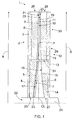
- Figure 1 is a schematic, more detailed side view of a single-disc high-consistency wood chip refiner 1.
- the refiner 1 comprises a stationary refining element 2, which may also be called a stator 2.
- the stationary refining element 2 comprises a fastening body 3 and one or more first, radially inner, blade elements 4 attached to the fastening body 3 at the inner circumference of the stationary refining element 2 and one or more second, radially outer, blade elements 8 attached to the fastening body 3 at the outer circumference of the stationary refining element 2.
- the one or more first blade elements 4 comprise blade bars 5 and blade grooves 6 therebetween, the blade bars 5 and the blade grooves 6 providing a radially inner, first stator refining surface 7.
- the first stator refining surface 7 provides an annular inner refining surface of the stationary refining element 2.
- the one or more second blade elements 8 comprise blade bars 9 and blade grooves 10 therebetween, the blade bars 9 and the blade grooves 10 providing a radially outer, second stator refining surface 11.
- the second stator refining surface 11 provides an annular outer refining surface of the stationary refining element 2.
- the inner and outer refining surfaces 7, 11 of the stationary refining element 2 together provide a refining surface of the stationary refining element 2.
- the blade bars denoted with reference marks 5 and 9 in Figure 1 form a guide bar the construction and purpose of which are discussed in more detail later.
- at least one of the first 4 and second 8 blade elements may also comprise conventional blade bars and blade grooves therebetween.
- the refiner 1 further comprises a rotatable refining element 12, which may also be called a rotor 12, the rotatable refining element 12 being opposed to the stationary refining element 2 such that there is a small distance, i.e., a blade gap 23 or a refining gap 23, between them.
- the rotatable refining element 12 comprises a fastening body 13 and one or more first, radially inner, blade elements 14 attached to the fastening body 13 at the inner circumference of the stationary refining element 12 and one or more second, radially outer, blade elements 18 attached to the fastening body 13 at the outer circumference of the rotatable refining element 12.
- the one or more first blade elements 14 comprise blade bars 15 and blade grooves 16 therebetween, the blade bars 15 and the blade grooves 16 providing a radially inner, first rotor refining surface 17.
- the first rotor refining surface 17 provides an annular inner refining surface of the rotatable refining element 12.
- the one or more second blade elements 18 comprise blade bars 19 and blade grooves 20 therebetween, the blade bars 19 and the blade grooves 20 providing a radially outer, second rotor refining surface 21.
- the second rotor refining surface 21 provides an annular outer refining surface of the rotatable refining element 12.
- the inner and outer refining surfaces 16, 21 of the rotatable refining element 12 together provide a refining surface of the rotatable refining element 12.
- the blade bars denoted with reference marks 15 and 19 in Figure 1 form a feed bar the construction and purpose of which are discussed in more detail later.
- at least one of the first 14 and second 18 blade elements may also comprise conventional blade bars and blade grooves therebetween.
- a feed opening 22 through which a suspension of water and wood chips to be refined is fed into the blade gap 23 between the stationary refining element 2 and the rotatable refining element 12.
- Steam flow carrying fibres is discharged out of the refiner 1 in a consistency of 25 - 75%.
- the rotatable refining element 12 is connected through a shaft 24 to a rotating motor (not shown) to rotate the rotatable refining element 12 relative to the stationary refining element 2.
- the refining surfaces of the stationary refining element 2 and the rotatable refining element 12 comprise, starting from the innermost edges 25, 27, i.e., inner circumferences 25, 27, of the stationary 2 and rotatable 12 refining elements or the centre of the refining elements 2, 12 and proceeding in the radial direction S of the refining elements 2, 12 towards the outermost edges 26, 28, i.e. outer circumferences 26, 28, of the stationary 2 and rotatable 12 refining elements, a number of successive refining surface zones having a varying effect on the material to be fed into the refiner 1.
- the treatment zone 30 may be composed of only a defibration zone or there may be a defibration zone 31 (shown in Figure 2 ) on the side of the feed zone 29 and a refining zone 32 (shown in Figure 2 ) on the side of the outer circumferences 26, 28 of the refining elements 2, 12.
- the feed zone 29 is intended to supply the material to be refined towards the treatment zone 30, whereas the defibration zone 31 is intended to defibrate the material to be refined, and the refining zone 32 is intended to actually refine the material to be refined.
- the treatment zone 30 may comprise only the defibration zone 31 or both the defibration zone 31 and the refining zone 32, the combination of the defibration zone 31 and the refining zone 32 providing a higher degree of refining.
- the feed zone 29 is arranged to extend to about 60 - 65% of the radial distance between the inner circumferences 25, 27 of the refining elements 2, 12 and the outer circumferences 26, 28 of the refining elements 2, 12 or, in other words, the feed zone 29 is arranged to be located at a radial distance of 0% to not more than 65% of the radius S of the refining elements 2, 12, i.e. the distance between the inner circumferences 25, 27 of the refining elements 2, 12 and the outer circumferences 26, 28 of the refining elements 2, 12, starting from the inner circumferences 25, 27 of the refining elements 2, 12 and extending towards the outer circumferences 26, 28 of the refining elements 2, 12.
- the treatment zone 30, in turn, is arranged to be located at a distance of about 60 - 100% of the radial distance between the inner circumferences 25, 27 of the refining elements 2, 12 and the outer circumferences 26, 28 of the refining elements 2, 12, starting from the inner circumferences 25, 27 of the refining elements 2, 12 and extending towards the outer circumferences 26, 28 of the refining elements 2, 12.
- the transition point from the feed zone 29 to the treatment zone 30 is denoted with a reference sign P, at which point there is an abrupt rise in height of the blade bar 9 in the second blade element 8 of the stationary refining element 2 towards the rotary refining element 12.
- the transition point P is the point where the feed zone 29 ends and the treatment zone 30 begins and it is located at a radial distance of 70 - 90%, preferably 75 - 80%, from the centre of the refiner 1 or at a radial distance of 50 - 80%, preferably 60 - 70%, from the innermost edge 25, 27 of the refining element 2, 12 or at a radial distance of 20 - 50%, preferably 30 - 40%, from the inner edge 34 of the outer blade element 8, 18, 33.
- the radius of the refiner 1 is the distance from the centre of the refiner 1 to the outer edge of a radially outermost blade element, and it is shown in Figure 1 by an arrow R.
- the radius R of the refiner 1 is the distance from the centre of the refiner 1 to the outer circumference of the radially outermost blade element.
- the radius of the refining element is the distance between the inner edge of a radially innermost blade element and the outer edge of a radially outermost blade element, and it is shown in Figure 1 by an arrow S.
- the radius S of the refining element is the distance between the inner circumference of the radially innermost blade element and the outer circumference of the radially outermost blade element.
- the radius of the outer blade element is the distance between the inner edge and the outer edge of the outer blade element. It is shown in Figure 2 by an arrow T. In other words, the radius T of the outer blade element is the distance between the inner circumference and the outer circumference of the outer blade element.
- Figure 1 discloses only one example of an embodiment of the single-disc high-consistency wood chip refiner according to the solution disclosed herein.
- the treatment zone 30 in the refining elements 2, 12 is arranged to be located at a distance of about 70% to 100%, preferably 75% to 100%, of the radius R of the refiner 1, starting from the centre of the refiner 1 and extending towards the outer circumferences 26, 28 of the refining elements 2, 12.
- the treatment zone 30 is arranged to be located at a distance of about 50% to 100%, preferably 60% to 100%, of the radius S of the refining elements 2, 12, from the inner edges 25, 27 of the refining elements 2, 12, or at a distance of about 20% to 100%, preferably from 30% to 100%, of the radius T of the outer blade elements 8, 18, from the inner edge 34 of the outer blade elements 8, 18.
- the treatment zone 30 is arranged to be located substantially closer to the outer circumferences 26, 28 of the refining elements 2, 12 than in conventional single-disc high-consistency wood chip refiners, and the feed zone 29 is thus arranged to extend, in the radial direction of the refining elements 2, 12, farther towards the outer circumferences 26, 28 of the refining elements 2, 12 than in conventional single-disc high-consistency wood chip refiners.
- the treatment zone 30 is arranged to be located in an area where the length of the treatment zone 30 in the circumferential direction of the refining elements 2, 12 is longer, i.e.
- a typical diameter of a blade element in a single-disc high-consistency wood chip refiner and in a double-disc high-consistency wood chip refiner is about 68 inches, or about 173 centimetres.
- defibration of the material to be refined takes place at a distance of about 60 centimetres of the radius of the refining element.
- the rotating frequency of both opposing refining elements both refining elements are arranged to rotate
- the impact frequency i.e. the number of impacts provided by the blade bars of the refining elements 2, 12 to the material to be refined, is about 2100 Hz.
- the defibration of the material to be refined when the defibration of the material to be refined is arranged to take place, for example, at a distance of about 70 centimetres of the radius of the refining element, i.e. at a distance of about 80% of the radius of the refiner, the circumferential speed at that distance from the centre of the refiner is about 17.5 m/s. If the distance of the leading edges of neighbouring blade bars is 8 millimetres, the impact frequency, i.e. the number of impacts provided by the blade bars of the refining elements 2, 12 to the material to be refined, is about 2100 Hz, i.e. the same as in conventional double-disc refiners.
- the treatment zone 30 may be composed of only the defibration zone 31 or, alternatively, the treatment zone 30 may comprise, in the radial direction S of the refining elements 2, 12, the defibration zone 31 followed by the refining zone 32.
- the defibration zone is arranged to be located at a distance of about 60 - 90% of the radius S of the refining elements 2, 12, starting from the centre of the refining elements 2, 12 or, preferably, at a distance of about 70 - 80% of the radius S of the refining elements 2, 12 from the centre of the refining elements 2, 12.
- the feed zone 29 of the rotatable refining element 12 comprises at least one, preferably more, feed bars 15, 19 extending towards the treatment zone 30 for feeding wood chips to be fed to the refiner 1 towards the treatment zones 30 of the refining elements 2, 12 of the refiner 1.
- the feed bars 15 and 19 extend in a direction from the inner circumference 27 of the rotatable refining element 12 towards the outer circumference 28 of the rotatable refining element 12, i.e. towards the treatment zone 30 of the rotatable refining element 12, and they may be aligned in the circumferential direction of the rotatable refining element 12 in such a way that the feed bar 15 in the first blade element 14 continues as the feed bar 19 in the second blade element 18.
- the heights of the feed bars 15, 19 at the feed zone 29 of the rotatable refining element 12 are arranged to decrease towards the outer circumference 28 of the rotatable refining element 12.
- the substantially great height of the feed bars 15, 19 on the side of the inner circumference 27 of the rotatable refining element 12 provides an effective feed of wood chips from the feed opening 22 towards the treatment zone 30.
- the height of the feed bars 19 on the annular outer refining surface of the rotatable refining element 12 will eventually decrease to a height corresponding to the height of conventional blade bars at the treatment zone 30, which can be seen more clearly in Figure 2 .
- the height of the feed bars 15, 19 at the feed zone 29 may be dimensioned in such a way that in a common cross-section of the stationary refining element 2 and the opposed rotatable refining element 12, which cross-section is in a direction crosswise to the radial direction of the refining elements, i.e. in the direction of the shaft 24 of the refiner 1, the feed bars 15, 19 of the rotatable refining element 12 are arranged to extend towards the stationary refining element 2 over an imaginary centre line of the common cross-section of the stationary refining element 2 and the opposed rotatable refining element 12, the imaginary centre line being denoted with a reference sign CL in Figure 1 .
- the centre line CL is a radial line which halves the blade gap 23 between the opposite refining elements 2, 12 in the height direction of the blade gap 23, the blade gap height being defined as a distance of blade groove 6, 16 bottoms of the opposite refining elements 2, 12 on the same radial level.
- the blade gap height is not uniform, but somewhat conical, and is wider at the inner circumferences 25, 27 of the refining elements 2, 12 and closes towards zero before the outer circumferences 26, 28 of the refining elements 2, 12, where the blade bars of the opposite refining elements 2, 12 almost touch each other.
- the feed bars 15, 19 of the rotatable refining element 12 extend towards the stationary refining element 2 over the imaginary centre line CL in such a way that the maximum height of the feed bar 15, 19 at the feed zone 29 of the rotatable second refining element 12 is 50 - 100%, preferably 60 - 95%, or more preferably 70 - 90%, of the height of the blade gap 23.
- the greater height of the feed bars 15, 19 on the side of the inner circumference of the rotatable refining element 12 will supply the wood chips effectively from the feed opening 22 towards the treatment zone 30, but the height of the feed bars 19 at the annular outer refining surface of the rotatable refining element 12 decrease to a height corresponding to the height of conventional blade bars at the treatment zone 30.
- the feed zone 29 of the stationary refining element 2 comprises at least one, preferably more, guide bars 5, 9 extending towards the treatment zone 30 for guiding the feed of wood chips to be fed to the refiner 1 towards the treatment zones 30 of the refining elements 2, 12 of the refiner 1.
- the guide bars 5 and 9 extend in a direction from the inner circumference of the stationary refining element 2 towards the outer circumference of the stationary refining element 2, and they may be aligned in the circumferential direction of the stationary refining element 2 in such a way that the guide bar 5 in the first blade element 4 continues as the guide bar 9 in the second blade element 9.
- the heights of the guide bars 5, 9 at the feed zone of the stationary refining element 2 are arranged to increase towards the outer circumference 26 of the stationary refining element 2 with a measure corresponding to the decrease of heights of the feed bars 15, 19 in the rotatable refining element 12.
- FIG. 2 is a schematic view of a blade element 33 for providing a part of the annular outer refining surface of the rotatable refining element 12.
- the blade element 33 has an inner edge 34, i.e. an inner circumference 34, to be directed towards the inner circumference 27 of the rotatable refining element 12, and an outer edge, i.e. an outer circumference 35, to be directed towards the outer circumference 28 of the rotatable refining element 12, as well as side edges 36, 37.
- the blade element 33 is fastened to the fastening body 13 with bolts, for example, inserted through fastening holes 38.
- Other fastening means are also possible, such as segment holders, when there are no holes on the blade surface.
- the blade element 33 of Figure 2 comprises, in the direction from the inner circumference 34 of the blade element 33 towards the outer circumference 35 of the blade element 33 or in the radial direction T of the blade element 33, a feed zone 29 followed by a treatment zone 30 comprising a defibration zone 31 and a refining zone 32.
- the feed zone 29 of the blade element 33 comprises feed bars 19, the height of which is arranged to decrease towards the outer circumference 35 of the blade element 33.
- the feed zone 29 of the blade element 33 may also comprise auxiliary blade bars 39, which may even out the flow of material at the feed zone 29.
- the defibration zone 31 and the refining zone 32 comprise conventional blade bars 40 and conventional blade grooves 41 therebetween.
- the blade bar 40 and blade groove 41 layout is substantially sparse to allow the blade bars of the opposite blade elements to defibrate wood chips effectively, whereas in the refining zone 32 the blade bar 40 and blade groove 41 layout is substantially dense to allow the blade bars of the opposite blade elements to refine the material defibrated in the defibration zone 31 effectively.
- the feed zone 29 is arranged to extend from the inner circumference 34 of the blade element 33 towards the outer circumference 35 of the blade element 33 to a maximum distance of about 40% or, alternatively, to a distance of about 30% or about 20% of the distance between the inner circumference 34 of the blade element 33 and the outer circumference 35 of the blade element 33, i.e. of the radius T of the blade element 33.
- the treatment zone 30 of the blade element 33 is arranged to be located at a distance of about 20% to 100% or, alternatively, at a distance of about 30% to 100% or at a distance of from about 40% to 100% of the distance between the inner circumference 34 of the blade element 33 and the outer circumference 35 of the blade element 33.
- the feed zone 29 may thus cover the first 0 - 40% of the radius T of the outer blade element.
- the treatment zone 30 may cover 20 - 100% of the radius T.
- the defibration zone 31 may extend from a minimum distance of 20% of the length of the radius T up to the outer edge 35 of the outer blade element, thus covering 20 - 100% of the radius T, or alternatively from about 20% to about 50 - 80% of the radius T, in which case the refining zone 32 covers the rest of the distance to the outer edge 35.
- the radial coverage is in the range of 0-35% for the feed zone 29, 30 - 60% for the defibration zone 31, and 50 - 100% for the refining zone 32.
- the blade element disclosed in Figure 2 is a blade segment intended to provide a part of the annular outer refining surface of the rotatable refining element 12, whereby the whole annular outer refining surface of the rotatable refining element 12 is provided by placing several blade segments of Figure 2 next to each other.
- a single annular blade element extending over the whole circumference of the rotatable refining element 12 may also be used to provide the whole annular outer refining surface of the rotatable refining element 12.
- the inner and outer refining surfaces of the stationary refining element 2 as well as the inner refining surface of the rotatable refining element 12 may also be formed of a number of blade segments placed next to each other or of a single annular blade element extending over the whole circumference of the stationary 2 or rotatable 12 refining element.
- FIG 3 is a schematic end view of the feed bar 19 in the feed zone 29.
- the intended rotation direction of the rotatable refining element is denoted with an arrow RD.
- the feed bar has a leading side 42 directed towards the rotation direction RD of the rotatable refining element 12 and a tailing side 43 directed to a direction opposite to the rotation direction RD of the rotatable refining element 12.
- the leading side 42 has a lower edge 44 at the bottom of the feed bar 19 and an upper edge 45 at the top of the feed bar 19.
- the feed bar 19 is tilted towards the rotation direction RD of the rotatable refining element 12 in such a way that the upper edge 45 of the feed bar 19 extends farther towards the rotation direction RD of the rotatable refining element 12 than the lower edge 44 of the feed bar 19.
- the tilting of the feed bar 19 towards the rotation direction RD of the rotatable refining element 12 prevents the wood chips to be fed into the refiner 1 from rising to the top of the feed bars 19, thereby preventing the wood chips from entering between the opposing refining elements and starting to defibrate before they enter to the actual treatment zone 30.
Landscapes
- Engineering & Computer Science (AREA)
- Food Science & Technology (AREA)
- Paper (AREA)
Abstract
Description
- The present invention relates to a single-disc high-consistency refiner for refining lignocellulosic material for paper and board manufacturing, comprising a stationary refining element and an opposed rotatable refining element, the stationary and rotatable refining elements each comprising at least one radially inner blade element providing an inner refining surface area of the refining element and at least one radially outer blade element providing an outer refining surface area of the refining element, the inner refining surface area and the outer refining surface area of each refining element together providing a refining surface of the refining element, and that there is a blade gap between the opposite refining elements having a height defined as a distance between bottoms of blade grooves of the opposite refining elements.
- The present invention also relates to a blade element for a rotatable disc-like refining element of a high-consistency refiner according to claim 1, the blade element being intended to provide at least part of a refining surface of the rotatable disc-like refining element and comprising an inner edge to be directed towards the centre of the refining element and an outer edge to be directed towards the outermost edge of the refining element and a refining surface provided with blade bars and blade grooves therebetween.
- Flat disc refiners for refining fibrous material for manufacturing paper and board typically comprise at least two opposite disc-like refining elements, at least one of which is rotating. A refining gap is provided between the two opposite elements. In so-called DD or double-disc refiners, both refining elements rotate in opposite directions, whereas in SD or single-disc refiners only one refining element rotates. A so-called Twin refiner is also a single-disc refiner comprising three refining elements, one of which is a rotatable element sandwiched between two stationary elements, whereby two refining gaps are provided.
- Single-disc high-consistency refiners for wood chips and fibres comprise a stationary disc-like refining element and an opposed rotatable disc-like refining element, and have a blade gap or a refining gap therebetween, a suspension of water and wood chips to be refined being fed into the blade gap. In most single-disc high-consistency refiners the stationary and rotatable refining elements comprise an annular inner refining surface area and an annular outer refining surface area composed of one or more blade elements, whereby the inner refining surface area and the outer refining surface area of each refining element together provide a complete refining surface of the refining element.
- Single-disc high-consistency wood chip refiners have a simple structure and operation. However, single-disc refiners typically operate with an undesirable high energy consumption and a low production capacity.
- One example of single-disc refiners is disclosed in WO publication 95/25199.
- An object of the present invention is to provide a novel single-disc high-consistency wood chip refiner as well as a novel blade element for a rotatable disc-like refining element.
- The single-disc refiner according to an invention is characterized in that the refining surfaces of the refining elements comprise, in a radial direction of the refining elements, a feed zone followed by a treatment zone, wherein a transition point from the feed zone to the treatment zone is located at a radial distance of 70 - 90% from the centre of the refiner or at a radial distance of 50 - 80% from the innermost edge of the refining element or at a radial distance of 20 - 50% from the inner edge of the outer blade element towards the outermost edge of the refining element, and that the feed zone of the refining surface of the rotatable refining element comprises at least one feed bar extending towards the treatment zone for feeding lignocellulosic material to be fed to the refiner towards the treatment zones of the refining elements of the refiner, and that the feed bar is arranged to extend towards the stationary refining element over an imaginary centre line halving the blade gap in the height direction of the blade gap, and that the height of the feed bar at the feed zone is arranged to decrease towards the outer circumference of the rotatable refining element, and that the maximum height of the feed bar at the feed zone of the rotatable refining element is 50 - 100%, preferably 60 - 95%, or more preferably 70 - 90%, of the height of the blade gap.
- The radius of the refiner is the distance from the centre of the refiner to the outer edge of a radially outermost blade element. In other words, the radius of the refiner is the distance from the centre of the refiner to the outer circumference of the radially outermost blade element.
- The radius of the refining element is the distance between the inner edge of a radially innermost blade element and the outer edge of a radially outermost blade element. In other words, the radius of the refining element is the distance between the inner circumference of the radially innermost blade element and the outer circumference of the radially outermost blade element.
- The radius of the outer blade element is the distance between the inner edge and the outer edge of the outer blade element. In other words, the radius of the outer blade element is the distance between the inner circumference and the outer circumference of the outer blade element.
- The blade element according to the invention is characterized in that the blade element is a blade segment and intended to provide a part of an outer refining surface area in the rotatable refining element comprising, in a radial direction of the refining element, an inner refining surface area followed by an outer refining surface area, and that the blade element comprises, in a direction from the inner edge of the blade element towards the outer edge of the blade element, a feed zone followed by a treatment zone, and that the treatment zone of the blade element is arranged to be located at a distance of about 20% to 100%, or alternatively at a distance of about 30% to 100%, or at a distance of about 40% to 100% of the distance between the inner edge of the blade element and the outer edge of the blade element, and that the feed zone comprises at least one feed bar extending towards the outer edge of the blade element and that the height of the feed bar at the feed zone is arranged to decrease towards the outer edge of the blade element.
- The invention is based on the idea of arranging in a single-disc refiner treatment zones on the refining surfaces of the opposing refining elements close to the outer circumferences of the refining elements. This means that the treatment zone is arranged to be located closer to the outer circumference of the refining element or of the blade element than conventionally, i.e., in an area where the length of the treatment zone in the circumferential direction of the refining elements is longer. With a proper blade bar and blade groove design and with conventional running speeds, it is possible to provide refining conditions substantially similar to those of the double-disc refiners. This means, for example, that a lower energy consumption is achieved when compared to conventional single-disc high-consistency wood chip refiners.
- According to an embodiment of the refiner, the treatment zone is arranged to be located at a distance of 50% to 100% of the radius of the refining element, or of 70% to 100% of the radius of the refiner, or of 20% to 100% of the radius of the outer blade element. Preferably, the treatment zone is arranged to be located at a distance of 60% to 100% of the radius of the refining element, or of 75% to 100% of the radius of the refiner, or of 30% to 100%, of the radius of the outer blade element.
- According to an embodiment of the refiner, the treatment zones of the refining surfaces of the refining elements comprise, in the radial direction of the refining elements, a defibration zone followed by a refining zone.
- According to an embodiment of the refiner, the defibration zone is arranged to be located at a distance of 60 to 90% of the radius of the refining element or, preferably, at a distance of 70 to 80% of the radius of the refining element, the rest up to 100% being a refining zone.
- According to an embodiment of the refiner, the feed bar has a leading side directed towards the rotation direction of the rotatable refining element, the leading side having a lower edge at the bottom of the feed bar and an upper edge at the top of the feed bar, and the feed bar is tilted towards the rotation direction of the rotatable refining element in such a way that the upper edge of the feed bar extends farther towards the rotation direction of the rotatable refining element than the lower edge of the feed bar.
- According to an embodiment of the refiner, the feed zone of the refining surface of the stationary refining element comprises at least one guide bar extending towards the treatment zone for guiding feed of the ligno-cellulosic material to be fed to the refiner towards the treatment zones of the refining elements of the refiner.
- According to an embodiment of the refiner, the height of the guide bar at the feed zone is arranged to increase towards the outer circumference of the stationary refining element.
- According to an embodiment of the blade element, the treatment zone of the refining surface of the blade element comprises, in a direction from the inner edge towards the outer edge, a defibration zone followed by a refining zone.
- According to an embodiment of the blade element, the feed bar has a leading side to be directed towards the rotation direction of the rotatable refining element, the leading side having a lower edge at the bottom of the feed bar and an upper edge at the top of the feed bar, and the feed bar is tilted towards the rotation direction of the rotatable refining element in such a way that the upper edge of the feed bar extends farther towards the rotation direction of the rotatable refining element than the lower edge of the feed bar.
- In the following the invention will be described in greater detail by means of preferred embodiments with reference to the accompanying drawings, in which
-
Figure 1 is a schematic side view of a part of a single-disc high-consistency wood chip refiner in cross-section; -
Figure 2 is a schematic view of a blade element as seen in the direction of the refining surface of the blade element; -
Figure 3 is a schematic end view of a feed bar; and -
Figure 4 is a schematic general side view of a single-disc high-consistency wood chip refiner in cross-section. - For the sake of clarity, the figures show some embodiments of the invention in a simplified manner. Like reference numerals identify like elements in the figures.
-
Figure 4 shows schematically a general side view of a single-disc high-consistency wood chip refiner 1 in cross-section. The refiner 1 is used for refining wood chips for providing fibrous wood material suitable to be used for manufacturing paper or paperboard. The refiner 1 comprises a disc-likestationary refining element 2, i.e., astator 2, and a disc-likerotatable refining element 12, i.e., arotor 12, which are positioned coaxially opposite to each other. Thestationary refining element 2 and therotatable refining element 12 comprise blade elements having blade bars and blade grooves therebetween, the blade bars and the blade grooves providing radially inner 7 and outer 11 refining surfaces in thestationary refining element 2 and radially inner 17 and outer 21 refining surfaces in therotatable refining element 12, for example. Therotatable refining element 12 is rotated by means of ashaft 24 in a manner known per se with a motor not shown for the sake of clarity, an exemplary rotation direction of therotary refining element 12 being shown by an arrow RD. Further,Figure 4 shows aloader 46 connected to affect therotatable refining element 12 via theshaft 4 in such a way that it can be pushed towards thestationary refining element 2 or pulled away from thestationary refining element 2, as shown schematically by an arrow A, to adjust ablade gap 23, i.e., arefining gap 23, between them. - The lignocellulose-containing material to be refined is fed through a feed opening 22 in the middle of the
stationary refining element 2 to theblade gap 23, where it is defibrated and refined at the same time as the water in the material vaporizes. The lignocellulose-containing material that has been defibrated and refined is discharged from theblade gap 23 through the outer edge of theblade gap 23 into arefiner chamber 47, from which it is further discharged out of the refiner 1 along adischarge channel 48. - The
refining elements Figure 4 , but with larger diameters therefining elements Figure 1 . -
Figure 1 is a schematic, more detailed side view of a single-disc high-consistency wood chip refiner 1.Figure 1 only discloses the upper half of the refiner 1. The refiner 1 comprises astationary refining element 2, which may also be called astator 2. Thestationary refining element 2 comprises a fasteningbody 3 and one or more first, radially inner,blade elements 4 attached to the fasteningbody 3 at the inner circumference of thestationary refining element 2 and one or more second, radially outer,blade elements 8 attached to the fasteningbody 3 at the outer circumference of thestationary refining element 2. The one or morefirst blade elements 4 compriseblade bars 5 andblade grooves 6 therebetween, theblade bars 5 and theblade grooves 6 providing a radially inner, first stator refining surface 7. The first stator refining surface 7 provides an annular inner refining surface of thestationary refining element 2. The one or moresecond blade elements 8 compriseblade bars 9 andblade grooves 10 therebetween, theblade bars 9 and theblade grooves 10 providing a radially outer, secondstator refining surface 11. The secondstator refining surface 11 provides an annular outer refining surface of thestationary refining element 2. The inner andouter refining surfaces 7, 11 of thestationary refining element 2 together provide a refining surface of thestationary refining element 2. The blade bars denoted withreference marks Figure 1 form a guide bar the construction and purpose of which are discussed in more detail later. In addition to one or more guide bars, at least one of the first 4 and second 8 blade elements may also comprise conventional blade bars and blade grooves therebetween. - The refiner 1 further comprises a
rotatable refining element 12, which may also be called arotor 12, therotatable refining element 12 being opposed to thestationary refining element 2 such that there is a small distance, i.e., ablade gap 23 or arefining gap 23, between them. Therotatable refining element 12 comprises afastening body 13 and one or more first, radially inner,blade elements 14 attached to thefastening body 13 at the inner circumference of thestationary refining element 12 and one or more second, radially outer,blade elements 18 attached to thefastening body 13 at the outer circumference of therotatable refining element 12. The one or morefirst blade elements 14 comprise blade bars 15 andblade grooves 16 therebetween, the blade bars 15 and theblade grooves 16 providing a radially inner, firstrotor refining surface 17. The firstrotor refining surface 17 provides an annular inner refining surface of therotatable refining element 12. The one or moresecond blade elements 18 comprise blade bars 19 and blade grooves 20 therebetween, the blade bars 19 and the blade grooves 20 providing a radially outer, secondrotor refining surface 21. The secondrotor refining surface 21 provides an annular outer refining surface of therotatable refining element 12. The inner and outer refining surfaces 16, 21 of therotatable refining element 12 together provide a refining surface of therotatable refining element 12. The blade bars denoted with reference marks 15 and 19 inFigure 1 form a feed bar the construction and purpose of which are discussed in more detail later. In addition to one or more feed bars, at least one of the first 14 and second 18 blade elements may also comprise conventional blade bars and blade grooves therebetween. - At the centre of the
stationary refining element 2 there is afeed opening 22 through which a suspension of water and wood chips to be refined is fed into theblade gap 23 between thestationary refining element 2 and therotatable refining element 12. Steam flow carrying fibres is discharged out of the refiner 1 in a consistency of 25 - 75%. Therotatable refining element 12 is connected through ashaft 24 to a rotating motor (not shown) to rotate therotatable refining element 12 relative to thestationary refining element 2. When therotatable refining element 12 rotates relative to thestationary refining element 2, wood chips fed into theblade gap 23 will be crushed, defibrated and refined and the refined fibrous wood material will move out of theblade gap 23 at the outer circumference of the stationary 2 and rotatable 12 refining elements. - The refining surfaces of the
stationary refining element 2 and therotatable refining element 12 comprise, starting from theinnermost edges inner circumferences refining elements refining elements outermost edges outer circumferences inner circumferences refining elements outer circumferences refining elements feed zone 29 followed by atreatment zone 30. Thetreatment zone 30 may be composed of only a defibration zone or there may be a defibration zone 31 (shown inFigure 2 ) on the side of thefeed zone 29 and a refining zone 32 (shown inFigure 2 ) on the side of theouter circumferences refining elements feed zone 29 is intended to supply the material to be refined towards thetreatment zone 30, whereas thedefibration zone 31 is intended to defibrate the material to be refined, and therefining zone 32 is intended to actually refine the material to be refined. Depending on the desired degree of refining, thetreatment zone 30 may comprise only thedefibration zone 31 or both thedefibration zone 31 and therefining zone 32, the combination of thedefibration zone 31 and therefining zone 32 providing a higher degree of refining. - In the example of
Figure 1 , thefeed zone 29 is arranged to extend to about 60 - 65% of the radial distance between theinner circumferences refining elements outer circumferences refining elements feed zone 29 is arranged to be located at a radial distance of 0% to not more than 65% of the radius S of therefining elements inner circumferences refining elements outer circumferences refining elements inner circumferences refining elements outer circumferences refining elements treatment zone 30, in turn, is arranged to be located at a distance of about 60 - 100% of the radial distance between theinner circumferences refining elements outer circumferences refining elements inner circumferences refining elements outer circumferences refining elements feed zone 29 to thetreatment zone 30 is denoted with a reference sign P, at which point there is an abrupt rise in height of theblade bar 9 in thesecond blade element 8 of thestationary refining element 2 towards therotary refining element 12. - The transition point P is the point where the
feed zone 29 ends and thetreatment zone 30 begins and it is located at a radial distance of 70 - 90%, preferably 75 - 80%, from the centre of the refiner 1 or at a radial distance of 50 - 80%, preferably 60 - 70%, from theinnermost edge refining element inner edge 34 of theouter blade element - The radius of the refiner 1 is the distance from the centre of the refiner 1 to the outer edge of a radially outermost blade element, and it is shown in
Figure 1 by an arrow R. In other words, the radius R of the refiner 1 is the distance from the centre of the refiner 1 to the outer circumference of the radially outermost blade element. - The radius of the refining element, in turn, is the distance between the inner edge of a radially innermost blade element and the outer edge of a radially outermost blade element, and it is shown in
Figure 1 by an arrow S. In other words, the radius S of the refining element is the distance between the inner circumference of the radially innermost blade element and the outer circumference of the radially outermost blade element. - The radius of the outer blade element is the distance between the inner edge and the outer edge of the outer blade element. It is shown in
Figure 2 by an arrow T. In other words, the radius T of the outer blade element is the distance between the inner circumference and the outer circumference of the outer blade element. -
Figure 1 discloses only one example of an embodiment of the single-disc high-consistency wood chip refiner according to the solution disclosed herein. Generally, in the single-disc high-consistency wood chip refiner according to the solution disclosed herein, thetreatment zone 30 in therefining elements outer circumferences refining elements treatment zone 30 is arranged to be located at a distance of about 50% to 100%, preferably 60% to 100%, of the radius S of therefining elements inner edges refining elements outer blade elements inner edge 34 of theouter blade elements - In the refiner disclosed above, the
treatment zone 30 is arranged to be located substantially closer to theouter circumferences refining elements feed zone 29 is thus arranged to extend, in the radial direction of therefining elements outer circumferences refining elements treatment zone 30 is arranged to be located in an area where the length of thetreatment zone 30 in the circumferential direction of therefining elements rotatable refining element 12 of the single-disc high-consistency wood chip refiners, it is possible to provide refining conditions, such as a number of impacts provided by the blade bars of therefining elements - Referring to the above, a typical diameter of a blade element in a single-disc high-consistency wood chip refiner and in a double-disc high-consistency wood chip refiner is about 68 inches, or about 173 centimetres. In conventional double-disc refiners, defibration of the material to be refined takes place at a distance of about 60 centimetres of the radius of the refining element. If the rotating frequency of both opposing refining elements (both refining elements are arranged to rotate) is 1500 rpm, the angular speed at that distance from the centre of the refining elements is 2 times 1500 rpm = 50 r/s, which means a circumferential speed of about 30 m/s. If the distance of leading edges of neighbouring blade bars is 14 millimetres, the impact frequency, i.e. the number of impacts provided by the blade bars of the
refining elements - In conventional single-disc refiners, defibration of the material to be refined takes place at a distance of about 40 centimetres of the radius of the refining element. When the rotating frequency of the rotatable refining element is 1500 rpm, the circumferential speed at that distance from the centre of the refining element is only about 10 m/s. This circumferential speed is much too low in order to achieve the refining conditions of a double-disc refiner in conventional single-disc refiners, because in practice it is not possible to provide such a blade bar and blade groove combination that would operate properly without becoming clogged with the material to be refined.
- However, in the single-disc high-consistency wood chip refiner disclosed herein, when the defibration of the material to be refined is arranged to take place, for example, at a distance of about 70 centimetres of the radius of the refining element, i.e. at a distance of about 80% of the radius of the refiner, the circumferential speed at that distance from the centre of the refiner is about 17.5 m/s. If the distance of the leading edges of neighbouring blade bars is 8 millimetres, the impact frequency, i.e. the number of impacts provided by the blade bars of the
refining elements - Below is a table representing a comparison made with a known conventional single-disc high-consistency wood chip refiner indicated with SD_C and a known conventional double-disc high-consistency wood chip refiner indicated with DD_C versus a single-disc high-consistency wood chip refiner according to the solution disclosed herein and indicated with SD_I. The known conventional refiner types were a 2-stage single-disc refiner SD 65/68 and a 1-stage double-disc refiner RGP 68 DD (both available from Valmet Corporation, Espoo, Finland). Pulp properties at a constant freeness level of 85 ml were analysed.
SD_C DD_C SD_I Total energy consumption [kwh/admt] 2250 1900 1850 Freeness CSF [ml] 85 85 85 Fibre length [mm] 1.5 1.35 1.2 Light scattering [m2/kg] 52.5 57 56 - The results show that, with the refiner according to the solution described, good optical properties close to the level of DD_C refined pulp and a clear improvement over the SD_C refined pulp may be achieved. Still, the fibre length loss compared to DD_C refined pulp is minor whereby the mechanical properties of the pulp are maintained on a sufficient level. Energy consumption is also 40% smaller compared to a conventional SD_C refiner, being about on the same level as in DD_C refiner or even below it.
- As shortly mentioned above, the
treatment zone 30 may be composed of only thedefibration zone 31 or, alternatively, thetreatment zone 30 may comprise, in the radial direction S of therefining elements defibration zone 31 followed by therefining zone 32. In the latter case, the defibration zone is arranged to be located at a distance of about 60 - 90% of the radius S of therefining elements refining elements refining elements refining elements - In the refiner 1 disclosed, the
feed zone 29 of therotatable refining element 12 comprises at least one, preferably more, feed bars 15, 19 extending towards thetreatment zone 30 for feeding wood chips to be fed to the refiner 1 towards thetreatment zones 30 of therefining elements inner circumference 27 of therotatable refining element 12 towards theouter circumference 28 of therotatable refining element 12, i.e. towards thetreatment zone 30 of therotatable refining element 12, and they may be aligned in the circumferential direction of therotatable refining element 12 in such a way that thefeed bar 15 in thefirst blade element 14 continues as thefeed bar 19 in thesecond blade element 18. The heights of the feed bars 15, 19 at thefeed zone 29 of therotatable refining element 12 are arranged to decrease towards theouter circumference 28 of therotatable refining element 12. The substantially great height of the feed bars 15, 19 on the side of theinner circumference 27 of therotatable refining element 12 provides an effective feed of wood chips from thefeed opening 22 towards thetreatment zone 30. The height of the feed bars 19 on the annular outer refining surface of therotatable refining element 12 will eventually decrease to a height corresponding to the height of conventional blade bars at thetreatment zone 30, which can be seen more clearly inFigure 2 . - The height of the feed bars 15, 19 at the
feed zone 29 may be dimensioned in such a way that in a common cross-section of thestationary refining element 2 and the opposedrotatable refining element 12, which cross-section is in a direction crosswise to the radial direction of the refining elements, i.e. in the direction of theshaft 24 of the refiner 1, the feed bars 15, 19 of therotatable refining element 12 are arranged to extend towards thestationary refining element 2 over an imaginary centre line of the common cross-section of thestationary refining element 2 and the opposedrotatable refining element 12, the imaginary centre line being denoted with a reference sign CL inFigure 1 . The centre line CL is a radial line which halves theblade gap 23 between theopposite refining elements blade gap 23, the blade gap height being defined as a distance ofblade groove opposite refining elements Figure 1 , the blade gap height is not uniform, but somewhat conical, and is wider at theinner circumferences refining elements outer circumferences refining elements opposite refining elements rotatable refining element 12 extend towards thestationary refining element 2 over the imaginary centre line CL in such a way that the maximum height of thefeed bar feed zone 29 of the rotatablesecond refining element 12 is 50 - 100%, preferably 60 - 95%, or more preferably 70 - 90%, of the height of theblade gap 23. The greater height of the feed bars 15, 19 on the side of the inner circumference of therotatable refining element 12 will supply the wood chips effectively from thefeed opening 22 towards thetreatment zone 30, but the height of the feed bars 19 at the annular outer refining surface of therotatable refining element 12 decrease to a height corresponding to the height of conventional blade bars at thetreatment zone 30. - In the refiner 1 disclosed, the
feed zone 29 of thestationary refining element 2 comprises at least one, preferably more, guidebars treatment zone 30 for guiding the feed of wood chips to be fed to the refiner 1 towards thetreatment zones 30 of therefining elements stationary refining element 2 towards the outer circumference of thestationary refining element 2, and they may be aligned in the circumferential direction of thestationary refining element 2 in such a way that theguide bar 5 in thefirst blade element 4 continues as theguide bar 9 in thesecond blade element 9. The heights of the guide bars 5, 9 at the feed zone of thestationary refining element 2 are arranged to increase towards theouter circumference 26 of thestationary refining element 2 with a measure corresponding to the decrease of heights of the feed bars 15, 19 in therotatable refining element 12. -
Figure 2 is a schematic view of ablade element 33 for providing a part of the annular outer refining surface of therotatable refining element 12. Theblade element 33 has aninner edge 34, i.e. aninner circumference 34, to be directed towards theinner circumference 27 of therotatable refining element 12, and an outer edge, i.e. anouter circumference 35, to be directed towards theouter circumference 28 of therotatable refining element 12, as well as side edges 36, 37. Theblade element 33 is fastened to thefastening body 13 with bolts, for example, inserted through fastening holes 38. Other fastening means are also possible, such as segment holders, when there are no holes on the blade surface. - The
blade element 33 ofFigure 2 comprises, in the direction from theinner circumference 34 of theblade element 33 towards theouter circumference 35 of theblade element 33 or in the radial direction T of theblade element 33, afeed zone 29 followed by atreatment zone 30 comprising adefibration zone 31 and arefining zone 32. Thefeed zone 29 of theblade element 33 comprises feed bars 19, the height of which is arranged to decrease towards theouter circumference 35 of theblade element 33. Thefeed zone 29 of theblade element 33 may also comprise auxiliary blade bars 39, which may even out the flow of material at thefeed zone 29. Thedefibration zone 31 and therefining zone 32 comprise conventional blade bars 40 andconventional blade grooves 41 therebetween. In thedefibration zone 31 theblade bar 40 andblade groove 41 layout is substantially sparse to allow the blade bars of the opposite blade elements to defibrate wood chips effectively, whereas in therefining zone 32 theblade bar 40 andblade groove 41 layout is substantially dense to allow the blade bars of the opposite blade elements to refine the material defibrated in thedefibration zone 31 effectively. - In the
blade element 33 disclosed above and intended to provide a part of the annular outer refining surface of therotatable refining element 12, thefeed zone 29 is arranged to extend from theinner circumference 34 of theblade element 33 towards theouter circumference 35 of theblade element 33 to a maximum distance of about 40% or, alternatively, to a distance of about 30% or about 20% of the distance between theinner circumference 34 of theblade element 33 and theouter circumference 35 of theblade element 33, i.e. of the radius T of theblade element 33. In other words, thetreatment zone 30 of theblade element 33 is arranged to be located at a distance of about 20% to 100% or, alternatively, at a distance of about 30% to 100% or at a distance of from about 40% to 100% of the distance between theinner circumference 34 of theblade element 33 and theouter circumference 35 of theblade element 33. - In the embodiment of
Figure 2 , thefeed zone 29 may thus cover the first 0 - 40% of the radius T of the outer blade element. Thetreatment zone 30 may cover 20 - 100% of the radius T. Thedefibration zone 31 may extend from a minimum distance of 20% of the length of the radius T up to theouter edge 35 of the outer blade element, thus covering 20 - 100% of the radius T, or alternatively from about 20% to about 50 - 80% of the radius T, in which case therefining zone 32 covers the rest of the distance to theouter edge 35. In a preferred embodiment, the radial coverage is in the range of 0-35% for thefeed zone 29, 30 - 60% for thedefibration zone 31, and 50 - 100% for therefining zone 32. - The blade element disclosed in
Figure 2 is a blade segment intended to provide a part of the annular outer refining surface of therotatable refining element 12, whereby the whole annular outer refining surface of therotatable refining element 12 is provided by placing several blade segments ofFigure 2 next to each other. Alternatively, a single annular blade element extending over the whole circumference of therotatable refining element 12 may also be used to provide the whole annular outer refining surface of therotatable refining element 12. The inner and outer refining surfaces of thestationary refining element 2 as well as the inner refining surface of therotatable refining element 12 may also be formed of a number of blade segments placed next to each other or of a single annular blade element extending over the whole circumference of the stationary 2 or rotatable 12 refining element. -
Figure 3 is a schematic end view of thefeed bar 19 in thefeed zone 29. InFigure 3 the intended rotation direction of the rotatable refining element is denoted with an arrow RD. The feed bar has a leadingside 42 directed towards the rotation direction RD of therotatable refining element 12 and a tailingside 43 directed to a direction opposite to the rotation direction RD of therotatable refining element 12. The leadingside 42 has alower edge 44 at the bottom of thefeed bar 19 and anupper edge 45 at the top of thefeed bar 19. Thefeed bar 19 is tilted towards the rotation direction RD of therotatable refining element 12 in such a way that theupper edge 45 of thefeed bar 19 extends farther towards the rotation direction RD of therotatable refining element 12 than thelower edge 44 of thefeed bar 19. The tilting of thefeed bar 19 towards the rotation direction RD of therotatable refining element 12 prevents the wood chips to be fed into the refiner 1 from rising to the top of the feed bars 19, thereby preventing the wood chips from entering between the opposing refining elements and starting to defibrate before they enter to theactual treatment zone 30. - Although the present solution is described in connection with wood chip refiners, it is clear for the person skilled in the art that the invention is applicable for fibre refining as well, such as further refining of reject fibers.
- It will be obvious to a person skilled in the art that, as technology advances, the inventive concept can be implemented in various ways. The invention and its embodiments are not limited to the examples described above but may vary within the scope of the claims.
Claims (10)
- A single-disc high-consistency refiner (1) for refining lignocellulosic material for paper and board manufacturing, comprising a stationary refining element (2) and an opposed rotatable refining element (12), the stationary (2) and rotatable (12) refining elements each comprising at least one radially inner blade element (4, 14) providing an inner refining surface area of the refining element (2, 12) and at least one radially outer blade element (8, 18) providing an outer refining surface area of the refining element (2, 12), the inner refining surface area and the outer refining surface area of each refining element (2, 12) together providing a refining surface of the refining element (2, 12), and that there is a blade gap (23) between the opposite refining elements (2, 12) having a height defined as a distance between bottoms of blade grooves (6, 10, 16, 20) of the opposite refining elements,
characterized in that
the refining surfaces of the refining elements (2, 12) comprise, in a radial direction of the refining elements (2, 12), a feed zone (29) followed by a treatment zone (30), wherein a transition point from the feed zone (29) to the treatment zone (30) is located at a radial distance of 70 - 90% from the centre of the refiner (1) or at a radial distance of 50 - 80% from the innermost edge (25, 27) of the refining element (2, 12) or at a radial distance of 20 - 50% from the inner edge (34) of the outer blade element (8, 18, 33) towards the outermost edge (26, 28) of the refining element (2, 12), and that
the feed zone (29) of the refining surface of the rotatable refining element (12) comprises at least one feed bar (15, 19) extending towards the treatment zone (30) for feeding lignocellulosic material to be fed to the refiner (1) towards the treatment zones (30) of the refining elements (2, 12) of the refiner (1), and that
the feed bar (15, 19) is arranged to extend towards the stationary refining element (2) over an imaginary centre line (CL) halving the blade gap (23) in the height direction of the blade gap (23), and that
the height of the feed bar (15, 19) at the feed zone (29) is arranged to decrease towards the outer circumference (28) of the rotatable refining element (12), and that
the maximum height of the feed bar (15, 19) at the feed zone (29) of the rotatable refining element (12) is 50 - 100%, preferably 60 - 95%, or more preferably 70 - 90%, of the height of the blade gap (23). - A refiner as claimed in claim 1, characterized in that the treatment zone (30) is arranged to be located at a distance of 50% to 100% of the radius of the refining element (2, 12), or of 70% to 100% of the radius of the refiner (1), or of 20% to 100% of the radius of the outer blade element (8, 18, 33).
- A refiner as claimed in claim 1 or 2, characterized in that the treatment zones (30) of the refining surfaces of the refining elements (2, 12) comprise, in the radial direction of the refining elements (2, 12), a defibration zone (31) followed by a refining zone (32).
- A refiner as claimed in claim 3, characterized in that the defibration zone (31) is arranged to be located at a distance of 60 to 90% of the radius (S) of the refining element (2, 12) or, preferably, at a distance of 70 to 80% of the radius (S) of the refining element (2, 12), the rest up to 100% being a refining zone (32).
- A refiner as claimed in claim 1, characterized in that the feed bar (15, 19) has a leading side (42) directed towards the rotation direction (RD) of the rotatable refining element (12), the leading side (42) having a lower edge (44) at the bottom of the feed bar (15, 19) and an upper edge (45) at the top of the feed bar (15, 19), and that the feed bar (15, 19) is tilted towards the rotation direction (RD) of the rotatable refining element (12) in such a way that the upper edge (45) of the feed bar (15, 19) extends farther towards the rotation direction (RD) of the rotatable refining element (12) than the lower edge (44) of the feed bar (15, 19).
- A refiner as claimed in any one of the preceding claims, char-acterized in that the feed zone (29) of the refining surface of the stationary refining element (2) comprises at least one guide bar (5, 9) extending towards the treatment zone (30) for guiding feed of the lignocellulosic material to be fed to the refiner (1) towards the treatment zones (30) of the refining elements (2, 12) of the refiner (1).
- A refiner as claimed in claim 6, characterized in that the height of the guide bar (5, 9) at the feed zone (29) is arranged to increase towards the outer circumference (26) of the stationary refining element (2).
- A blade element (33) for a rotatable disc-like refining element (12) of a high-consistency refiner according to claim 1, the blade element (33) being intended to provide at least part of a refining surface of the rotatable disc-like refining element (12) and comprising an inner edge (34) to be directed towards the centre of the refining element (12) and an outer edge (35) to be directed towards the outermost edge (28) of the refining element (12) and a refining surface (21) provided with blade bars and blade grooves therebetween, characterized in that
the blade element (33) is a blade segment and intended to provide a part of an outer refining surface area in the rotatable refining element (12) comprising, in a radial direction (S) of the refining element (12), an inner refining surface area followed by an outer refining surface area, and that the blade element (33) comprises, in a direction from the inner edge (34) of the blade element (33) towards the outer edge (35) of the blade element (33), a feed zone (29) followed by a treatment zone (30), and that the treatment zone (30) of the blade element (33) is arranged to be located at a distance of about 20% to 100%, or alternatively at a distance of about 30% to 100%, or at a distance of about 40% to 100% of the distance between the inner edge (34) of the blade element (33) and the outer edge (35) of the blade element (33), and that
the feed zone (29) comprises at least one feed bar (19) extending towards the outer edge (35) of the blade element (33) and that the height of the feed bar (19) at the feed zone (29) is arranged to decrease towards the outer edge (35) of the blade element (33). - A blade element as claimed in claim 8, characterized in that the treatment zone (30) of the refining surface (21) of the blade element (33) comprises, in a direction from the inner edge (34) towards the outer edge (35), a defibration zone (31) followed by a refining zone (32).
- A blade element as claimed in claim 8 or 9, characterized in that the feed bar (19) has a leading side (42) to be directed towards the rotation direction (RD) of the rotatable refining element (12), the leading side (42) having a lower edge (44) at the bottom of the feed bar (19) and an upper edge (45) at the top of the feed bar (19), and that the feed bar (19) is tilted towards the rotation direction (RD) of the rotatable refining element (12) in such a way that the upper edge (45) of the feed bar (19) extends farther towards the rotation direction (RD) of the rotatable refining element (12) than the lower edge (44) of the feed bar (19).
Applications Claiming Priority (1)
| Application Number | Priority Date | Filing Date | Title |
|---|---|---|---|
| FI20145620A FI127628B (en) | 2014-06-26 | 2014-06-26 | Single-disc refiner |
Publications (2)
| Publication Number | Publication Date |
|---|---|
| EP2960367A1 true EP2960367A1 (en) | 2015-12-30 |
| EP2960367B1 EP2960367B1 (en) | 2024-02-14 |
Family
ID=53610760
Family Applications (1)
| Application Number | Title | Priority Date | Filing Date |
|---|---|---|---|
| EP15173287.2A Active EP2960367B1 (en) | 2014-06-26 | 2015-06-23 | Single-disc refiner |
Country Status (5)
| Country | Link |
|---|---|
| US (1) | US10441954B2 (en) |
| EP (1) | EP2960367B1 (en) |
| JP (1) | JP6122908B2 (en) |
| CN (1) | CN105220553B (en) |
| FI (1) | FI127628B (en) |
Cited By (4)
| Publication number | Priority date | Publication date | Assignee | Title |
|---|---|---|---|---|
| WO2019136069A1 (en) * | 2018-01-02 | 2019-07-11 | International Paper Company | Apparatus and method for processing wood fibers |
| US10794003B2 (en) | 2018-01-02 | 2020-10-06 | International Paper Company | Apparatus and method for processing wood fibers |
| US11001968B2 (en) | 2018-01-02 | 2021-05-11 | International Paper Company | Apparatus and method for processing wood fibers |
| US11421382B2 (en) | 2018-01-02 | 2022-08-23 | International Paper Company | Apparatus and method for processing wood fibers |
Families Citing this family (1)
| Publication number | Priority date | Publication date | Assignee | Title |
|---|---|---|---|---|
| SE543334C2 (en) * | 2019-11-18 | 2020-12-01 | Valmet Oy | Refiner for refining lignocellulosic material and refining segments for such a refiner |
Citations (4)
| Publication number | Priority date | Publication date | Assignee | Title |
|---|---|---|---|---|
| US3387796A (en) * | 1965-02-04 | 1968-06-11 | Jones Division | Defibrating device |
| US3473745A (en) * | 1967-01-11 | 1969-10-21 | Sprout Waldron & Co Inc | Refining plate for high consistency pulp |
| US5383617A (en) * | 1993-10-21 | 1995-01-24 | Deuchars; Ian | Refiner plates with asymmetric inlet pattern |
| WO1995025199A1 (en) | 1994-03-15 | 1995-09-21 | Beloit Technologies, Inc. | Breaker bar section for a high consistency refiner |
Family Cites Families (27)
| Publication number | Priority date | Publication date | Assignee | Title |
|---|---|---|---|---|
| US3552664A (en) | 1968-06-28 | 1971-01-05 | Black Clawson Co | Disc-type |
| US3974971A (en) | 1972-04-13 | 1976-08-17 | Rolf Bertil Reinhall | Grinding discs for defibering fibrous material |
| US3910511A (en) * | 1974-05-20 | 1975-10-07 | Westvaco Corp | Open discharge pulp refiner |
| SE8302013L (en) * | 1983-04-12 | 1984-10-13 | Sunds Defibrator | DEVICE FOR MALAPPLANTS FOR REFINING LIGNOCELLULOSALLY MATERIAL |
| US5181664A (en) | 1992-04-17 | 1993-01-26 | Andritz Sprout-Bauer, Inc. | Grinding plate with angled outer bars |
| SE470566B (en) | 1993-01-14 | 1994-08-29 | Sunds Defibrator Ind Ab | Grinding elements intended for a disk mill for defibration and processing of lignocellulosic fibrous material |
| SE503168C2 (en) | 1994-08-18 | 1996-04-15 | Sunds Defibrator Ind Ab | A pair of interacting template elements |
| SE516965C2 (en) * | 1997-02-25 | 2002-03-26 | Valmet Fibertech Ab | Methods for mechanical processing of lignocellulosic fibrous material in a grinder and feed device for such grinder |
| US6402071B1 (en) * | 1999-11-23 | 2002-06-11 | Durametal Corporation | Refiner plates with injector inlet |
| SE516619C2 (en) * | 2000-06-08 | 2002-02-05 | Valmet Fibertech Ab | Grinding segments and grinding apparatus for refining lignocellulosic material comprising the grinding segment |
| SE518463C2 (en) * | 2001-02-15 | 2002-10-15 | Metso Paper Inc | A pair of opposing interacting grinding elements intended for a disc refiner for atomizing and refining lignocellulosic material |
| FI118971B (en) * | 2002-07-02 | 2008-05-30 | Metso Paper Inc | Refiner |
| DE10258324B4 (en) | 2002-12-13 | 2008-03-27 | Voith Patent Gmbh | Process for the production of sets for the milling of hydrous paper pulp |
| CN1756600A (en) * | 2003-03-04 | 2006-04-05 | 希格玛精机株式会社 | Crusher |
| US7104480B2 (en) * | 2004-03-23 | 2006-09-12 | J&L Fiber Services, Inc. | Refiner sensor and coupling arrangement |
| US7300540B2 (en) * | 2004-07-08 | 2007-11-27 | Andritz Inc. | Energy efficient TMP refining of destructured chips |
| US7531219B2 (en) * | 2005-07-21 | 2009-05-12 | Hi-Tex, Inc. | Treated textile fabric |
| FI122364B (en) * | 2006-01-30 | 2011-12-30 | Metso Paper Inc | refiner |
| US20070210197A1 (en) | 2006-03-10 | 2007-09-13 | Carpenter Charles T | Refiner plate |
| FI121509B (en) * | 2007-11-30 | 2010-12-15 | Metso Paper Inc | Refiner stator refiner surface, refiner surface steel segment and refiner |
| FI123898B (en) * | 2008-03-19 | 2013-12-13 | Metso Paper Inc | Grinder or dispersant blade |
| DE102008039003A1 (en) | 2008-08-21 | 2010-02-25 | Voith Patent Gmbh | Method for grinding water-suspended cellulose fibers, involves guiding fibers in aqueous suspension between grinding sets provided with grinding blocks |
| US9708765B2 (en) | 2011-07-13 | 2017-07-18 | Andritz Inc. | Rotor refiner plate element for counter-rotating refiner having curved bars and serrated leading edges |
| US9085850B2 (en) * | 2012-04-13 | 2015-07-21 | Andritz Inc. | Reversible low energy refiner plates |
| US9968938B2 (en) * | 2012-09-17 | 2018-05-15 | Andritz Inc. | Refiner plate with gradually changing geometry |
| US9352326B2 (en) * | 2012-10-23 | 2016-05-31 | Lee Tech Llc | Grind mill for dry mill industry |
| US9145641B2 (en) * | 2012-12-13 | 2015-09-29 | Andritz Inc. | Apparatus for disperser plate and method to refine paper |
-
2014
- 2014-06-26 FI FI20145620A patent/FI127628B/en active IP Right Grant
-
2015
- 2015-06-15 CN CN201510329154.XA patent/CN105220553B/en active Active
- 2015-06-23 EP EP15173287.2A patent/EP2960367B1/en active Active
- 2015-06-24 JP JP2015126087A patent/JP6122908B2/en active Active
- 2015-06-25 US US14/751,020 patent/US10441954B2/en active Active
Patent Citations (4)
| Publication number | Priority date | Publication date | Assignee | Title |
|---|---|---|---|---|
| US3387796A (en) * | 1965-02-04 | 1968-06-11 | Jones Division | Defibrating device |
| US3473745A (en) * | 1967-01-11 | 1969-10-21 | Sprout Waldron & Co Inc | Refining plate for high consistency pulp |
| US5383617A (en) * | 1993-10-21 | 1995-01-24 | Deuchars; Ian | Refiner plates with asymmetric inlet pattern |
| WO1995025199A1 (en) | 1994-03-15 | 1995-09-21 | Beloit Technologies, Inc. | Breaker bar section for a high consistency refiner |
Cited By (10)
| Publication number | Priority date | Publication date | Assignee | Title |
|---|---|---|---|---|
| WO2019136069A1 (en) * | 2018-01-02 | 2019-07-11 | International Paper Company | Apparatus and method for processing wood fibers |
| CN111630225A (en) * | 2018-01-02 | 2020-09-04 | 国际纸业公司 | Apparatus and method for processing wood fibers |
| US10794003B2 (en) | 2018-01-02 | 2020-10-06 | International Paper Company | Apparatus and method for processing wood fibers |
| US11001968B2 (en) | 2018-01-02 | 2021-05-11 | International Paper Company | Apparatus and method for processing wood fibers |
| US11421382B2 (en) | 2018-01-02 | 2022-08-23 | International Paper Company | Apparatus and method for processing wood fibers |
| CN111630225B (en) * | 2018-01-02 | 2023-01-10 | 国际纸业公司 | Apparatus and method for processing wood fibers |
| US11905658B2 (en) | 2018-01-02 | 2024-02-20 | International Paper Company | Apparatus and method for processing wood fibers |
| US11965290B2 (en) | 2018-01-02 | 2024-04-23 | International Paper Company | Apparatus and method for processing wood fibers |
| US11982054B2 (en) | 2018-01-02 | 2024-05-14 | International Paper Company | Apparatus and method for processing wood fibers |
| US12553182B2 (en) | 2018-01-02 | 2026-02-17 | International Paper Company | Apparatus and method for processing wood fibers |
Also Published As
| Publication number | Publication date |
|---|---|
| US20150375231A1 (en) | 2015-12-31 |
| JP2016008373A (en) | 2016-01-18 |
| CN105220553A (en) | 2016-01-06 |
| US10441954B2 (en) | 2019-10-15 |
| EP2960367B1 (en) | 2024-02-14 |
| FI127628B (en) | 2018-10-31 |
| CN105220553B (en) | 2017-09-12 |
| JP6122908B2 (en) | 2017-04-26 |
Similar Documents
| Publication | Publication Date | Title |
|---|---|---|
| EP2960367B1 (en) | Single-disc refiner | |
| CN101883893B (en) | Refiner | |
| CA2528398C (en) | Refiner | |
| FI126263B (en) | Blade element for refiner and refiner for refining fiber material | |
| AU2001264491B2 (en) | A refining segment and a refining apparatus comprising a refining disc with such refining segment | |
| JP7754391B2 (en) | Blade elements for refiners | |
| AU721789B2 (en) | Feeding element for fibrous material | |
| US20240263395A1 (en) | Refining Segment | |
| CA2604639C (en) | Disc housing | |
| US7451946B2 (en) | Refining element | |
| US5047118A (en) | Method for decreasing energy consumption during refining of fiber material at a reduced grinding frequency while maintaining capacity | |
| US5152871A (en) | Method for decreasing energy consumption during refining of fiber material while maintaining capacity |
Legal Events
| Date | Code | Title | Description |
|---|---|---|---|
| PUAI | Public reference made under article 153(3) epc to a published international application that has entered the european phase |
Free format text: ORIGINAL CODE: 0009012 |
|
| AK | Designated contracting states |
Kind code of ref document: A1 Designated state(s): AL AT BE BG CH CY CZ DE DK EE ES FI FR GB GR HR HU IE IS IT LI LT LU LV MC MK MT NL NO PL PT RO RS SE SI SK SM TR |
|
| AX | Request for extension of the european patent |
Extension state: BA ME |
|
| 17P | Request for examination filed |
Effective date: 20160620 |
|
| RBV | Designated contracting states (corrected) |
Designated state(s): AL AT BE BG CH CY CZ DE DK EE ES FI FR GB GR HR HU IE IS IT LI LT LU LV MC MK MT NL NO PL PT RO RS SE SI SK SM TR |
|
| RAP1 | Party data changed (applicant data changed or rights of an application transferred) |
Owner name: VALMET TECHNOLOGIES OY |
|
| STAA | Information on the status of an ep patent application or granted ep patent |
Free format text: STATUS: EXAMINATION IS IN PROGRESS |
|
| 17Q | First examination report despatched |
Effective date: 20210428 |
|
| GRAP | Despatch of communication of intention to grant a patent |
Free format text: ORIGINAL CODE: EPIDOSNIGR1 |
|
| STAA | Information on the status of an ep patent application or granted ep patent |
Free format text: STATUS: GRANT OF PATENT IS INTENDED |
|
| INTG | Intention to grant announced |
Effective date: 20230411 |
|
| P01 | Opt-out of the competence of the unified patent court (upc) registered |
Effective date: 20230602 |
|
| GRAJ | Information related to disapproval of communication of intention to grant by the applicant or resumption of examination proceedings by the epo deleted |
Free format text: ORIGINAL CODE: EPIDOSDIGR1 |
|
| STAA | Information on the status of an ep patent application or granted ep patent |
Free format text: STATUS: EXAMINATION IS IN PROGRESS |
|
| GRAP | Despatch of communication of intention to grant a patent |
Free format text: ORIGINAL CODE: EPIDOSNIGR1 |
|
| STAA | Information on the status of an ep patent application or granted ep patent |
Free format text: STATUS: GRANT OF PATENT IS INTENDED |
|
| INTC | Intention to grant announced (deleted) | ||
| INTG | Intention to grant announced |
Effective date: 20230912 |
|
| GRAS | Grant fee paid |
Free format text: ORIGINAL CODE: EPIDOSNIGR3 |
|
| GRAA | (expected) grant |
Free format text: ORIGINAL CODE: 0009210 |
|
| STAA | Information on the status of an ep patent application or granted ep patent |
Free format text: STATUS: THE PATENT HAS BEEN GRANTED |
|
| AK | Designated contracting states |
Kind code of ref document: B1 Designated state(s): AL AT BE BG CH CY CZ DE DK EE ES FI FR GB GR HR HU IE IS IT LI LT LU LV MC MK MT NL NO PL PT RO RS SE SI SK SM TR |
|
| REG | Reference to a national code |
Ref country code: GB Ref legal event code: FG4D |
|
| REG | Reference to a national code |
Ref country code: CH Ref legal event code: EP |
|
| REG | Reference to a national code |
Ref country code: DE Ref legal event code: R096 Ref document number: 602015087520 Country of ref document: DE |
|
| REG | Reference to a national code |
Ref country code: IE Ref legal event code: FG4D |
|
| REG | Reference to a national code |
Ref country code: LT Ref legal event code: MG9D |
|
| REG | Reference to a national code |
Ref country code: NL Ref legal event code: MP Effective date: 20240214 |
|
| PG25 | Lapsed in a contracting state [announced via postgrant information from national office to epo] |
Ref country code: IS Free format text: LAPSE BECAUSE OF FAILURE TO SUBMIT A TRANSLATION OF THE DESCRIPTION OR TO PAY THE FEE WITHIN THE PRESCRIBED TIME-LIMIT Effective date: 20240614 |
|
| PG25 | Lapsed in a contracting state [announced via postgrant information from national office to epo] |
Ref country code: LT Free format text: LAPSE BECAUSE OF FAILURE TO SUBMIT A TRANSLATION OF THE DESCRIPTION OR TO PAY THE FEE WITHIN THE PRESCRIBED TIME-LIMIT Effective date: 20240214 |
|
| PG25 | Lapsed in a contracting state [announced via postgrant information from national office to epo] |
Ref country code: GR Free format text: LAPSE BECAUSE OF FAILURE TO SUBMIT A TRANSLATION OF THE DESCRIPTION OR TO PAY THE FEE WITHIN THE PRESCRIBED TIME-LIMIT Effective date: 20240515 |
|
| REG | Reference to a national code |
Ref country code: AT Ref legal event code: MK05 Ref document number: 1657093 Country of ref document: AT Kind code of ref document: T Effective date: 20240214 |
|
| PG25 | Lapsed in a contracting state [announced via postgrant information from national office to epo] |
Ref country code: HR Free format text: LAPSE BECAUSE OF FAILURE TO SUBMIT A TRANSLATION OF THE DESCRIPTION OR TO PAY THE FEE WITHIN THE PRESCRIBED TIME-LIMIT Effective date: 20240214 Ref country code: RS Free format text: LAPSE BECAUSE OF FAILURE TO SUBMIT A TRANSLATION OF THE DESCRIPTION OR TO PAY THE FEE WITHIN THE PRESCRIBED TIME-LIMIT Effective date: 20240514 Ref country code: NL Free format text: LAPSE BECAUSE OF FAILURE TO SUBMIT A TRANSLATION OF THE DESCRIPTION OR TO PAY THE FEE WITHIN THE PRESCRIBED TIME-LIMIT Effective date: 20240214 |
|
| PG25 | Lapsed in a contracting state [announced via postgrant information from national office to epo] |
Ref country code: ES Free format text: LAPSE BECAUSE OF FAILURE TO SUBMIT A TRANSLATION OF THE DESCRIPTION OR TO PAY THE FEE WITHIN THE PRESCRIBED TIME-LIMIT Effective date: 20240214 |
|
| PG25 | Lapsed in a contracting state [announced via postgrant information from national office to epo] |
Ref country code: AT Free format text: LAPSE BECAUSE OF FAILURE TO SUBMIT A TRANSLATION OF THE DESCRIPTION OR TO PAY THE FEE WITHIN THE PRESCRIBED TIME-LIMIT Effective date: 20240214 |
|
| PG25 | Lapsed in a contracting state [announced via postgrant information from national office to epo] |
Ref country code: RS Free format text: LAPSE BECAUSE OF FAILURE TO SUBMIT A TRANSLATION OF THE DESCRIPTION OR TO PAY THE FEE WITHIN THE PRESCRIBED TIME-LIMIT Effective date: 20240514 Ref country code: NO Free format text: LAPSE BECAUSE OF FAILURE TO SUBMIT A TRANSLATION OF THE DESCRIPTION OR TO PAY THE FEE WITHIN THE PRESCRIBED TIME-LIMIT Effective date: 20240514 Ref country code: NL Free format text: LAPSE BECAUSE OF FAILURE TO SUBMIT A TRANSLATION OF THE DESCRIPTION OR TO PAY THE FEE WITHIN THE PRESCRIBED TIME-LIMIT Effective date: 20240214 Ref country code: LT Free format text: LAPSE BECAUSE OF FAILURE TO SUBMIT A TRANSLATION OF THE DESCRIPTION OR TO PAY THE FEE WITHIN THE PRESCRIBED TIME-LIMIT Effective date: 20240214 Ref country code: IS Free format text: LAPSE BECAUSE OF FAILURE TO SUBMIT A TRANSLATION OF THE DESCRIPTION OR TO PAY THE FEE WITHIN THE PRESCRIBED TIME-LIMIT Effective date: 20240614 Ref country code: HR Free format text: LAPSE BECAUSE OF FAILURE TO SUBMIT A TRANSLATION OF THE DESCRIPTION OR TO PAY THE FEE WITHIN THE PRESCRIBED TIME-LIMIT Effective date: 20240214 Ref country code: GR Free format text: LAPSE BECAUSE OF FAILURE TO SUBMIT A TRANSLATION OF THE DESCRIPTION OR TO PAY THE FEE WITHIN THE PRESCRIBED TIME-LIMIT Effective date: 20240515 Ref country code: FI Free format text: LAPSE BECAUSE OF FAILURE TO SUBMIT A TRANSLATION OF THE DESCRIPTION OR TO PAY THE FEE WITHIN THE PRESCRIBED TIME-LIMIT Effective date: 20240214 Ref country code: ES Free format text: LAPSE BECAUSE OF FAILURE TO SUBMIT A TRANSLATION OF THE DESCRIPTION OR TO PAY THE FEE WITHIN THE PRESCRIBED TIME-LIMIT Effective date: 20240214 Ref country code: BG Free format text: LAPSE BECAUSE OF FAILURE TO SUBMIT A TRANSLATION OF THE DESCRIPTION OR TO PAY THE FEE WITHIN THE PRESCRIBED TIME-LIMIT Effective date: 20240214 Ref country code: AT Free format text: LAPSE BECAUSE OF FAILURE TO SUBMIT A TRANSLATION OF THE DESCRIPTION OR TO PAY THE FEE WITHIN THE PRESCRIBED TIME-LIMIT Effective date: 20240214 |
|
| PG25 | Lapsed in a contracting state [announced via postgrant information from national office to epo] |
Ref country code: PT Free format text: LAPSE BECAUSE OF FAILURE TO SUBMIT A TRANSLATION OF THE DESCRIPTION OR TO PAY THE FEE WITHIN THE PRESCRIBED TIME-LIMIT Effective date: 20240614 Ref country code: PL Free format text: LAPSE BECAUSE OF FAILURE TO SUBMIT A TRANSLATION OF THE DESCRIPTION OR TO PAY THE FEE WITHIN THE PRESCRIBED TIME-LIMIT Effective date: 20240214 |
|
| PG25 | Lapsed in a contracting state [announced via postgrant information from national office to epo] |
Ref country code: SE Free format text: LAPSE BECAUSE OF FAILURE TO SUBMIT A TRANSLATION OF THE DESCRIPTION OR TO PAY THE FEE WITHIN THE PRESCRIBED TIME-LIMIT Effective date: 20240214 Ref country code: PT Free format text: LAPSE BECAUSE OF FAILURE TO SUBMIT A TRANSLATION OF THE DESCRIPTION OR TO PAY THE FEE WITHIN THE PRESCRIBED TIME-LIMIT Effective date: 20240614 Ref country code: PL Free format text: LAPSE BECAUSE OF FAILURE TO SUBMIT A TRANSLATION OF THE DESCRIPTION OR TO PAY THE FEE WITHIN THE PRESCRIBED TIME-LIMIT Effective date: 20240214 Ref country code: LV Free format text: LAPSE BECAUSE OF FAILURE TO SUBMIT A TRANSLATION OF THE DESCRIPTION OR TO PAY THE FEE WITHIN THE PRESCRIBED TIME-LIMIT Effective date: 20240214 |
|
| PG25 | Lapsed in a contracting state [announced via postgrant information from national office to epo] |
Ref country code: DK Free format text: LAPSE BECAUSE OF FAILURE TO SUBMIT A TRANSLATION OF THE DESCRIPTION OR TO PAY THE FEE WITHIN THE PRESCRIBED TIME-LIMIT Effective date: 20240214 |
|
| PG25 | Lapsed in a contracting state [announced via postgrant information from national office to epo] |
Ref country code: SM Free format text: LAPSE BECAUSE OF FAILURE TO SUBMIT A TRANSLATION OF THE DESCRIPTION OR TO PAY THE FEE WITHIN THE PRESCRIBED TIME-LIMIT Effective date: 20240214 |
|
| PG25 | Lapsed in a contracting state [announced via postgrant information from national office to epo] |
Ref country code: CZ Free format text: LAPSE BECAUSE OF FAILURE TO SUBMIT A TRANSLATION OF THE DESCRIPTION OR TO PAY THE FEE WITHIN THE PRESCRIBED TIME-LIMIT Effective date: 20240214 Ref country code: EE Free format text: LAPSE BECAUSE OF FAILURE TO SUBMIT A TRANSLATION OF THE DESCRIPTION OR TO PAY THE FEE WITHIN THE PRESCRIBED TIME-LIMIT Effective date: 20240214 |
|
| PG25 | Lapsed in a contracting state [announced via postgrant information from national office to epo] |
Ref country code: SK Free format text: LAPSE BECAUSE OF FAILURE TO SUBMIT A TRANSLATION OF THE DESCRIPTION OR TO PAY THE FEE WITHIN THE PRESCRIBED TIME-LIMIT Effective date: 20240214 |
|
| PG25 | Lapsed in a contracting state [announced via postgrant information from national office to epo] |
Ref country code: SM Free format text: LAPSE BECAUSE OF FAILURE TO SUBMIT A TRANSLATION OF THE DESCRIPTION OR TO PAY THE FEE WITHIN THE PRESCRIBED TIME-LIMIT Effective date: 20240214 Ref country code: SK Free format text: LAPSE BECAUSE OF FAILURE TO SUBMIT A TRANSLATION OF THE DESCRIPTION OR TO PAY THE FEE WITHIN THE PRESCRIBED TIME-LIMIT Effective date: 20240214 Ref country code: RO Free format text: LAPSE BECAUSE OF FAILURE TO SUBMIT A TRANSLATION OF THE DESCRIPTION OR TO PAY THE FEE WITHIN THE PRESCRIBED TIME-LIMIT Effective date: 20240214 Ref country code: EE Free format text: LAPSE BECAUSE OF FAILURE TO SUBMIT A TRANSLATION OF THE DESCRIPTION OR TO PAY THE FEE WITHIN THE PRESCRIBED TIME-LIMIT Effective date: 20240214 Ref country code: DK Free format text: LAPSE BECAUSE OF FAILURE TO SUBMIT A TRANSLATION OF THE DESCRIPTION OR TO PAY THE FEE WITHIN THE PRESCRIBED TIME-LIMIT Effective date: 20240214 Ref country code: CZ Free format text: LAPSE BECAUSE OF FAILURE TO SUBMIT A TRANSLATION OF THE DESCRIPTION OR TO PAY THE FEE WITHIN THE PRESCRIBED TIME-LIMIT Effective date: 20240214 |
|
| REG | Reference to a national code |
Ref country code: DE Ref legal event code: R097 Ref document number: 602015087520 Country of ref document: DE |
|
| PG25 | Lapsed in a contracting state [announced via postgrant information from national office to epo] |
Ref country code: IT Free format text: LAPSE BECAUSE OF FAILURE TO SUBMIT A TRANSLATION OF THE DESCRIPTION OR TO PAY THE FEE WITHIN THE PRESCRIBED TIME-LIMIT Effective date: 20240214 |
|
| PLBE | No opposition filed within time limit |
Free format text: ORIGINAL CODE: 0009261 |
|
| STAA | Information on the status of an ep patent application or granted ep patent |
Free format text: STATUS: NO OPPOSITION FILED WITHIN TIME LIMIT |
|
| PG25 | Lapsed in a contracting state [announced via postgrant information from national office to epo] |
Ref country code: IT Free format text: LAPSE BECAUSE OF FAILURE TO SUBMIT A TRANSLATION OF THE DESCRIPTION OR TO PAY THE FEE WITHIN THE PRESCRIBED TIME-LIMIT Effective date: 20240214 |
|
| 26N | No opposition filed |
Effective date: 20241115 |
|
| PG25 | Lapsed in a contracting state [announced via postgrant information from national office to epo] |
Ref country code: MC Free format text: LAPSE BECAUSE OF FAILURE TO SUBMIT A TRANSLATION OF THE DESCRIPTION OR TO PAY THE FEE WITHIN THE PRESCRIBED TIME-LIMIT Effective date: 20240214 |
|
| REG | Reference to a national code |
Ref country code: CH Ref legal event code: PL |
|
| PG25 | Lapsed in a contracting state [announced via postgrant information from national office to epo] |
Ref country code: LU Free format text: LAPSE BECAUSE OF NON-PAYMENT OF DUE FEES Effective date: 20240623 |
|
| GBPC | Gb: european patent ceased through non-payment of renewal fee |
Effective date: 20240623 |
|
| PG25 | Lapsed in a contracting state [announced via postgrant information from national office to epo] |
Ref country code: IE Free format text: LAPSE BECAUSE OF NON-PAYMENT OF DUE FEES Effective date: 20240623 |
|
| PG25 | Lapsed in a contracting state [announced via postgrant information from national office to epo] |
Ref country code: SI Free format text: LAPSE BECAUSE OF FAILURE TO SUBMIT A TRANSLATION OF THE DESCRIPTION OR TO PAY THE FEE WITHIN THE PRESCRIBED TIME-LIMIT Effective date: 20240214 Ref country code: CH Free format text: LAPSE BECAUSE OF NON-PAYMENT OF DUE FEES Effective date: 20240630 Ref country code: BE Free format text: LAPSE BECAUSE OF NON-PAYMENT OF DUE FEES Effective date: 20240630 |
|
| PG25 | Lapsed in a contracting state [announced via postgrant information from national office to epo] |
Ref country code: GB Free format text: LAPSE BECAUSE OF NON-PAYMENT OF DUE FEES Effective date: 20240623 |
|
| REG | Reference to a national code |
Ref country code: BE Ref legal event code: MM Effective date: 20240630 |
|
| PGFP | Annual fee paid to national office [announced via postgrant information from national office to epo] |
Ref country code: DE Payment date: 20250618 Year of fee payment: 11 |
|
| PGFP | Annual fee paid to national office [announced via postgrant information from national office to epo] |
Ref country code: FR Payment date: 20250625 Year of fee payment: 11 |
|
| PG25 | Lapsed in a contracting state [announced via postgrant information from national office to epo] |
Ref country code: CY Free format text: LAPSE BECAUSE OF FAILURE TO SUBMIT A TRANSLATION OF THE DESCRIPTION OR TO PAY THE FEE WITHIN THE PRESCRIBED TIME-LIMIT; INVALID AB INITIO Effective date: 20150623 |
|
| PG25 | Lapsed in a contracting state [announced via postgrant information from national office to epo] |
Ref country code: HU Free format text: LAPSE BECAUSE OF FAILURE TO SUBMIT A TRANSLATION OF THE DESCRIPTION OR TO PAY THE FEE WITHIN THE PRESCRIBED TIME-LIMIT; INVALID AB INITIO Effective date: 20150623 |