EP2960373A1 - Mur de guidage en béton - Google Patents
Mur de guidage en béton Download PDFInfo
- Publication number
- EP2960373A1 EP2960373A1 EP15166325.9A EP15166325A EP2960373A1 EP 2960373 A1 EP2960373 A1 EP 2960373A1 EP 15166325 A EP15166325 A EP 15166325A EP 2960373 A1 EP2960373 A1 EP 2960373A1
- Authority
- EP
- European Patent Office
- Prior art keywords
- concrete
- guide wall
- concrete guide
- wall according
- reinforcing element
- Prior art date
- Legal status (The legal status is an assumption and is not a legal conclusion. Google has not performed a legal analysis and makes no representation as to the accuracy of the status listed.)
- Withdrawn
Links
Images

Classifications
-
- E—FIXED CONSTRUCTIONS
- E01—CONSTRUCTION OF ROADS, RAILWAYS, OR BRIDGES
- E01F—ADDITIONAL WORK, SUCH AS EQUIPPING ROADS OR THE CONSTRUCTION OF PLATFORMS, HELICOPTER LANDING STAGES, SIGNS, SNOW FENCES, OR THE LIKE
- E01F15/00—Safety arrangements for slowing, redirecting or stopping errant vehicles, e.g. guard posts or bollards; Arrangements for reducing damage to roadside structures due to vehicular impact
- E01F15/02—Continuous barriers extending along roads or between traffic lanes
- E01F15/08—Continuous barriers extending along roads or between traffic lanes essentially made of walls or wall-like elements ; Cable-linked blocks
- E01F15/081—Continuous barriers extending along roads or between traffic lanes essentially made of walls or wall-like elements ; Cable-linked blocks characterised by the use of a specific material
- E01F15/083—Continuous barriers extending along roads or between traffic lanes essentially made of walls or wall-like elements ; Cable-linked blocks characterised by the use of a specific material using concrete
Definitions
- the invention relates to a Betonleitwand for road boundary.
- Concrete guide walls for road boundary have a concrete body. Within the concrete body usually several longitudinally extending reinforcing elements in the form of steel cables or the like are arranged. Such concrete protection walls are for example in DE 10 145 647 and DE 10 2005 030 412 described.
- Such concrete guide walls are made for example as in-situ concrete baffles.
- the first plurality of reinforcing elements are arranged for example on or next to the roadway.
- the individual longitudinally adjoining reinforcing elements overlap each other or are usually joined together by welding.
- the production of the concrete guide wall, within which the reinforcing elements are arranged takes place mechanically as in-situ concrete guide wall.
- the reinforcing elements are lifted by the machine to be brought into the exact later horizontal and vertical position.
- the concrete wall is made by casting by means of concrete.
- joints are provided during the manufacturing process of the concrete guide wall. Such joints are usually provided at a distance of four to six meters. These joints must be filled after hardening of the concrete, for example, with elastic joint material. Despite such elastic filling of the joints leaks may occur especially after several years, leading to the ingress of water and thus to corrosion of the reinforcing elements.
- the object of the invention is therefore to provide a concrete barrier to the roadway boundary, which has a long service life.
- the concrete guide wall according to the invention for road boundary has a concrete body.
- the reinforcing elements extend in particular in the longitudinal direction of the concrete body. To avoid corrosion of the at least one reinforcing element this is encased according to the invention. Due to the sheathing of the at least one reinforcing element according to the invention, it is ensured that, despite the penetration of water, there is no corrosion which impairs the stability of the reinforcing element.
- the sheath according to the invention need not extend over the entire length of the at least one reinforcing element. Rather, it may be sufficient to provide appropriate sheathing in particularly vulnerable areas. These are, in particular, also joints provided with in-situ concrete guide walls, which are provided to compensate for shrinkage, the occurrence of temperature fluctuations, etc.
- the sheathing is a plastic sheath.
- the plastic coating comprises polyolefins, in particular polypropylenes, polyethylenes, mixtures thereof or copolymers.
- the at least one reinforcing element may be a reinforcing element having a plurality of strands.
- the plurality of strands are connected by twisting, braiding or the like to a reinforcing element, for example.
- at least a part of the strands is encased, which in particular is again a plastic casing, as described above.
- the reinforcing elements in particular having a plurality of strands, preferably comprise steel and, in a particularly preferred embodiment, are made of structural steel.
- the concrete body can be a concrete body produced as a sideways concrete wall. This is produced directly on site by appropriate machines. Alternatively, it may also be mobile concrete guide walls. Such mobile concrete guide walls are used, for example, to delineate construction sites or in the area of road boundaries, which must be openable.
- the concrete guide wall preferably has a stepped and / or flared cross-section.
- the Betonleitwand is thus narrower at an upper side than at an underside.
- the concrete guide wall has a head part, wherein the head part extends in particular over a height of 50% - 60% of the total height of the concrete guide wall. Measured by an upper edge, the head part preferably has a height of 40 cm - 60 cm, preferably 45 cm - 55 cm. It is further preferred that within the head part at least two, and more preferably at least three, reinforcing elements are arranged. It is particularly preferred that an upper reinforcing element has a distance from the upper edge of the head part of at least 10 cm, in particular at least 15 cm.
- Another second reinforcing element seen from above preferably has a distance of 10 cm-15 cm from the upper reinforcing element. It is particularly preferred that a third reinforcing element in the head part is provided, which in turn to the second reinforcing element has a distance of 10 cm - 15 cm.
- the at least two, in particular three reinforcing elements in the head part are arranged horizontally one above the other in a plane.
- the movement elements are preferably in the longitudinal direction at least partially, preferably completely, around coated reinforcement elements.
- the reinforcing elements are preferably arranged in a vertical plane or vertically superimposed.
- the head part of the concrete guide wall according to the invention preferably has a width of 20 cm to 30 cm extending transversely to the longitudinal direction of the concrete guide wall.
- the concrete guide wall according to the invention preferably has a foot part which has a width of 50 cm to 70 cm, preferably 55 cm to 65 cm, on a footprint.
- the footprint is the underside of the Betonleitwand on which the Betonleitwand is set up or arranged, for example, on the road or on a concrete foundation or other type of foundation.
- the foot part preferably has a height of 30 cm - 50 cm.
- an approach is arranged on the footprint, which may optionally also have a greater width.
- the approach projects into a groove of corresponding dimensions provided in the foundation, the road surface or in a concrete foundation or the like.
- the approach preferably has a height of at least 4 cm, in particular at least 6 cm.
- the groove Transverse to the longitudinal direction of the concrete guide wall, the groove has a width of at least 20 cm, in particular at least 30 cm, particularly preferably at least 35 cm.
- the approach preferably has no interruption.
- a retention level of H2 can be achieved. This can be achieved in particular with an overall height of the concrete protective wall of about 90 cm.
- the concrete protective wall according to the invention may in particular be a concrete protective wall which is symmetrical with respect to a vertical plane, it being preferred that the reinforcing elements are also arranged in this plane.
- a concrete protective wall is particularly suitable for lateral roadway boundary.
- the concrete protective wall is formed as an asymmetrical concrete protective wall, wherein a pointing in the direction of the road front has a flared foot, similar to the symmetrical concrete protective wall.
- the facing away from the roadway back has no such issued foot, but a particular flat, preferably inclined surface.
- Such unbalanced concrete protection walls are particularly suitable for placement in the region of the central strip. It is particularly preferred that such concrete protection walls are arranged in the median strip of a highway with their backs facing each other.
- the intermediate space of these concrete protective walls is preferably backfilled with soil or the like.
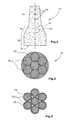
- a concrete guide wall 10 may, for example, in Fig. 1 having outer contour shown, wherein the outer contours can vary depending on the type of Betonleitwand and the purpose of use.
- the outer contours can vary depending on the type of Betonleitwand and the purpose of use.
- three reinforcing elements 16 extending in the longitudinal direction are arranged in particular in an upper region 14 or a head part of the concrete body.
- the longitudinal direction is perpendicular to the plane of the drawing.
- the individual reinforcing elements 16 can, for example, as in Fig. 2 or Fig. 3 be constructed shown.
- the individual reinforcing elements 16 have a plurality of strands 18, in particular made of steel. These are surrounded by a common casing 20. This can be, as in Fig. 2 shown to be a casting. Likewise, it is also possible that a tubular sheath is pushed as a jacket, for example, over the strands 18 and thus over the entire reinforcing element.
- all individual strands 18 are each surrounded by a sheath 22 or each have a tubular casing.
- FIGS. 2 and 3 illustrated embodiments are also combined with each other.
- the concrete guide wall can be a stepped concrete guide wall 10, as in FIG Fig. 1 represented, act. This is symmetrical in particular to a running in the longitudinal direction of the concrete guide center plane 24. Furthermore, it is preferred that the particular three reinforcing elements 16 are arranged horizontally one above the other in the middle plane 24.
- a particular stepped concrete guide wall 10 has a foot part 26 and a transition region 28.
- the head part 14 has a relatively small width, in particular 20 cm - 30 cm, the width increases slightly downwards.
- the foot part has a width of 60 cm - 100 cm in the area of a footprint 31. Usual overall heights of such concrete guide walls are in the range of 80 cm - 100 cm.
- concrete guide wall 30 is formed asymmetrically to a vertical plane 32.
- the at least two, in the illustratedariesbeispeil three, reinforcing elements 16 are arranged.
- the reinforcing elements 16 may also be uncoated, conventional reinforcing elements, in particular steel cables.
- the concrete guide wall 30 has a head part 14 whose height is 40 cm - 60 cm.
- the head part has a height of 49 cm.
- the width of the head part increases downwards, towards the foot part.
- the head part 14 is adjoined by the foot part 26, wherein the transition between the head part and the foot part is formed by a radius, so that a continuous, flowing transition is produced.
- the radius is in the range of 30 cm - 40 cm, wherein the radius is approximately 35 cm in the illustrated embodiment.
- the foot part 26 has a height of 30 cm - 40 cm in the preferred embodiment.
- the foot part comprises a base 34 which has a height of 5 cm - 10 cm. In this case, the foot part in the illustrated embodiment has a total height of 41 cm, wherein the base has a height of about 8 cm.
- a rear side 36 of the concrete guide wall 30 is formed obliquely, so that even on the back of the concrete guide wall 30 is a broadening.
- the straight back 36 formed to an angle to an angle of 4 ° - 8 °. In the illustrated embodiment, the angle is about 6 °.
- the head part has a width of 20 cm to 30 cm in the widest region. At an upper side 38, the width is preferably about 20 cm.
- a front side 40 of the head part 14 is also inclined outwards and has a vertical angle of 6 ° - 10 °, in the illustrated embodiment about 8 ° on.
- a likewise flat front side 42 of the foot part 26 has an angle to a vertical of preferably 34 ° - 38 °, in the illustrated embodiment, about 36 °, on.
- a projection 44 on an installation surface 31 is the provision of a projection 44 on an installation surface 31.
- the projection 44 protrudes into a groove 46.
- the groove 46 is provided in a concrete foundation 48. Instead of the concrete foundation 48, it may also be a roadway or other suitable foundation.
- the projection 44 preferably has a height of 5 cm - 10 cm and a width of 20 cm - 40 cm.
- the groove 46 has corresponding dimensions. In the illustrated embodiment, the approach has a height of about 5 cm and a width of about 35 cm.
- Corresponding ASI values and values of the holding level can also be achieved with a larger width of the concrete guide wall and thus an effective range W2.
- the in Fig. 4 shown concrete guide wall 30 may be formed, for example, as a symmetrical to the plane 32 wall, then both sides corresponding to the in Fig. 4 left side of the concrete guide wall 30 would be formed.
- the preferably three reinforcing elements 16 are in particular as above based on the FIGS. 2 or 3 described trained.
Landscapes
- Engineering & Computer Science (AREA)
- Architecture (AREA)
- Civil Engineering (AREA)
- Structural Engineering (AREA)
- Refuge Islands, Traffic Blockers, Or Guard Fence (AREA)
- Road Signs Or Road Markings (AREA)
Applications Claiming Priority (1)
| Application Number | Priority Date | Filing Date | Title |
|---|---|---|---|
| DE202014005167.4U DE202014005167U1 (de) | 2014-06-27 | 2014-06-27 | Betonleitwand |
Publications (1)
| Publication Number | Publication Date |
|---|---|
| EP2960373A1 true EP2960373A1 (fr) | 2015-12-30 |
Family
ID=53434185
Family Applications (1)
| Application Number | Title | Priority Date | Filing Date |
|---|---|---|---|
| EP15166325.9A Withdrawn EP2960373A1 (fr) | 2014-06-27 | 2015-05-05 | Mur de guidage en béton |
Country Status (2)
| Country | Link |
|---|---|
| EP (1) | EP2960373A1 (fr) |
| DE (1) | DE202014005167U1 (fr) |
Cited By (1)
| Publication number | Priority date | Publication date | Assignee | Title |
|---|---|---|---|---|
| EP4582633A1 (fr) | 2024-01-03 | 2025-07-09 | Linetech GmbH & Co. KG | Mur de contrôle du trafic |
Families Citing this family (1)
| Publication number | Priority date | Publication date | Assignee | Title |
|---|---|---|---|---|
| BE1031664B1 (nl) * | 2023-06-02 | 2025-01-13 | Beheersmaatschappij Antwerpen Mobiel Bam | Wegbarrière-inrichting en wegbarrièresysteem |
Citations (8)
| Publication number | Priority date | Publication date | Assignee | Title |
|---|---|---|---|---|
| EP0393013A1 (fr) * | 1989-04-12 | 1990-10-17 | Vorspann-Technik Gesellschaft m.b.H. | Faisceau d'élément de tension constitué de membres de contrainte comme cordons, barres ou câbles |
| WO1997017510A1 (fr) * | 1995-11-08 | 1997-05-15 | Armacel Pty. Limited | Barre ou tuyau gaine |
| US5685665A (en) * | 1996-05-09 | 1997-11-11 | Lembo; M. Carl | Roadway barrier and method of installation |
| DE10145647C1 (de) | 2001-09-15 | 2003-01-16 | Tss Tech Sicherheits Systeme G | Abgestuftes Rückhaltesystem an Straßen aus Beton |
| DE20303254U1 (de) * | 2003-02-28 | 2004-07-08 | Wirtgen Gmbh | Beton-Schutzwand |
| DE102005030412A1 (de) | 2005-06-30 | 2007-01-04 | Tss Technische Sicherheits-Systeme Gmbh | Rückhaltesystem |
| DE202008006604U1 (de) * | 2008-05-15 | 2008-08-07 | Dipl.-Ing. Winfried Schnabel Gmbh | Korrosionssichere Fugenüberdeckung |
| DE202013102049U1 (de) * | 2013-05-10 | 2013-06-07 | Kirchdorfer Fertigteilholding Gmbh | Ortbetonschutzwand |
-
2014
- 2014-06-27 DE DE202014005167.4U patent/DE202014005167U1/de not_active Expired - Lifetime
-
2015
- 2015-05-05 EP EP15166325.9A patent/EP2960373A1/fr not_active Withdrawn
Patent Citations (8)
| Publication number | Priority date | Publication date | Assignee | Title |
|---|---|---|---|---|
| EP0393013A1 (fr) * | 1989-04-12 | 1990-10-17 | Vorspann-Technik Gesellschaft m.b.H. | Faisceau d'élément de tension constitué de membres de contrainte comme cordons, barres ou câbles |
| WO1997017510A1 (fr) * | 1995-11-08 | 1997-05-15 | Armacel Pty. Limited | Barre ou tuyau gaine |
| US5685665A (en) * | 1996-05-09 | 1997-11-11 | Lembo; M. Carl | Roadway barrier and method of installation |
| DE10145647C1 (de) | 2001-09-15 | 2003-01-16 | Tss Tech Sicherheits Systeme G | Abgestuftes Rückhaltesystem an Straßen aus Beton |
| DE20303254U1 (de) * | 2003-02-28 | 2004-07-08 | Wirtgen Gmbh | Beton-Schutzwand |
| DE102005030412A1 (de) | 2005-06-30 | 2007-01-04 | Tss Technische Sicherheits-Systeme Gmbh | Rückhaltesystem |
| DE202008006604U1 (de) * | 2008-05-15 | 2008-08-07 | Dipl.-Ing. Winfried Schnabel Gmbh | Korrosionssichere Fugenüberdeckung |
| DE202013102049U1 (de) * | 2013-05-10 | 2013-06-07 | Kirchdorfer Fertigteilholding Gmbh | Ortbetonschutzwand |
Cited By (1)
| Publication number | Priority date | Publication date | Assignee | Title |
|---|---|---|---|---|
| EP4582633A1 (fr) | 2024-01-03 | 2025-07-09 | Linetech GmbH & Co. KG | Mur de contrôle du trafic |
Also Published As
| Publication number | Publication date |
|---|---|
| DE202014005167U1 (de) | 2015-10-01 |
Similar Documents
| Publication | Publication Date | Title |
|---|---|---|
| EP2158363B1 (fr) | Système de retenue de véhicules rempli ou remplissable destiné à délimiter des voies de circulation | |
| DE102008049966B3 (de) | Anschluss für eine Verkehrsleitwand | |
| EP2960373A1 (fr) | Mur de guidage en béton | |
| DE202012001738U1 (de) | Verbindungsvorrichtung für eine Betonschutzwand an Straßen | |
| EP3075908B1 (fr) | Rainure de fente | |
| DE102007024993A1 (de) | Fahrzeug-Rückhaltesystem an Verkehrswegen | |
| EP4392615B1 (fr) | Structure souterraine pour le guidage d'une conduite | |
| DE102014209121B4 (de) | Übergangskonstruktion für Fahrbahnbegrenzungen | |
| DE202008003111U1 (de) | Fahrzeugrückhaltesystem mit vergrößerter Auflagefläche zum Begrenzen von Fahrbahnen | |
| EP2893083B1 (fr) | Mur de protection en béton coulé sur place | |
| DE102012112023B4 (de) | Fußbodenbauschalungselement | |
| DE202010002141U1 (de) | Überbrückungselement sowie Fahrbahnbegrenzungselement | |
| EP2893084B1 (fr) | Mur de protection en béton coulé sur place | |
| EP3369862B1 (fr) | Élément de chéneau destiné à former un canal d'écoulement des eaux | |
| DE202013102049U1 (de) | Ortbetonschutzwand | |
| AT526888B1 (de) | Betonleitwandelement für ein fahrzeugrückhaltesystem | |
| DE202019106295U1 (de) | Schachtdeckel-Umrandungsplatte | |
| DE202014011004U1 (de) | Flanschprofil zur Herstellung einer Spundwandbohle, sowie eine Spundwandbohle | |
| DE2556724C2 (de) | Verbundpfahl | |
| DE2913394C2 (de) | Zusammengesetzte Spundwand | |
| DE102014212507A1 (de) | Reparierter Betonleitwand-Abschnitt | |
| DE3685881T2 (de) | Stuetzbauwerk und verfahren zum verwirklichen dieses stuetzbauwerks. | |
| DE102022116323A1 (de) | Fahrzeugrückhalte- und/oder Lärmschutzsystem mit Fertigteilfundament | |
| DE202014001281U1 (de) | Betonleitwand | |
| EP4582633A1 (fr) | Mur de contrôle du trafic |
Legal Events
| Date | Code | Title | Description |
|---|---|---|---|
| PUAI | Public reference made under article 153(3) epc to a published international application that has entered the european phase |
Free format text: ORIGINAL CODE: 0009012 |
|
| AK | Designated contracting states |
Kind code of ref document: A1 Designated state(s): AL AT BE BG CH CY CZ DE DK EE ES FI FR GB GR HR HU IE IS IT LI LT LU LV MC MK MT NL NO PL PT RO RS SE SI SK SM TR |
|
| AX | Request for extension of the european patent |
Extension state: BA ME |
|
| 17P | Request for examination filed |
Effective date: 20160624 |
|
| RBV | Designated contracting states (corrected) |
Designated state(s): AL AT BE BG CH CY CZ DE DK EE ES FI FR GB GR HR HU IE IS IT LI LT LU LV MC MK MT NL NO PL PT RO RS SE SI SK SM TR |
|
| STAA | Information on the status of an ep patent application or granted ep patent |
Free format text: STATUS: EXAMINATION IS IN PROGRESS |
|
| 17Q | First examination report despatched |
Effective date: 20171109 |
|
| STAA | Information on the status of an ep patent application or granted ep patent |
Free format text: STATUS: THE APPLICATION IS DEEMED TO BE WITHDRAWN |
|
| 18D | Application deemed to be withdrawn |
Effective date: 20200924 |