EP2960385B1 - Flüssigkeitsdosiereinheit für ein toilettenspülsystem - Google Patents
Flüssigkeitsdosiereinheit für ein toilettenspülsystem Download PDFInfo
- Publication number
- EP2960385B1 EP2960385B1 EP15173310.2A EP15173310A EP2960385B1 EP 2960385 B1 EP2960385 B1 EP 2960385B1 EP 15173310 A EP15173310 A EP 15173310A EP 2960385 B1 EP2960385 B1 EP 2960385B1
- Authority
- EP
- European Patent Office
- Prior art keywords
- hose
- water
- dosing
- detergent
- dosing unit
- Prior art date
- Legal status (The legal status is an assumption and is not a legal conclusion. Google has not performed a legal analysis and makes no representation as to the accuracy of the status listed.)
- Active
Links
Images


Classifications
-
- E—FIXED CONSTRUCTIONS
- E03—WATER SUPPLY; SEWERAGE
- E03D—WATER-CLOSETS OR URINALS WITH FLUSHING DEVICES; FLUSHING VALVES THEREFOR
- E03D9/00—Sanitary or other accessories for lavatories ; Devices for cleaning or disinfecting the toilet room or the toilet bowl; Devices for eliminating smells
- E03D9/02—Devices adding a disinfecting, deodorising, or cleaning agent to the water while flushing
- E03D9/03—Devices adding a disinfecting, deodorising, or cleaning agent to the water while flushing consisting of a separate container with an outlet through which the agent is introduced into the flushing water, e.g. by suction ; Devices for agents in direct contact with flushing water
- E03D9/031—Devices connected to or dispensing into the flushing pipe
-
- E—FIXED CONSTRUCTIONS
- E03—WATER SUPPLY; SEWERAGE
- E03D—WATER-CLOSETS OR URINALS WITH FLUSHING DEVICES; FLUSHING VALVES THEREFOR
- E03D9/00—Sanitary or other accessories for lavatories ; Devices for cleaning or disinfecting the toilet room or the toilet bowl; Devices for eliminating smells
- E03D9/02—Devices adding a disinfecting, deodorising, or cleaning agent to the water while flushing
- E03D9/03—Devices adding a disinfecting, deodorising, or cleaning agent to the water while flushing consisting of a separate container with an outlet through which the agent is introduced into the flushing water, e.g. by suction ; Devices for agents in direct contact with flushing water
- E03D9/033—Devices placed inside or dispensing into the cistern
- E03D9/038—Passive dispensers, i.e. without moving parts
Definitions
- the present invention relates to a liquid dosing unit for toilet flushing system.
- the present invention relates to a liquid dosing unit for providing detergent to a WC suit.
- Another system operates by allowing a solid state chemical to partly dissolve during flushing.
- the present invention preferably seeks to mitigate or eliminate one or more of the above-identified deficiencies in the art singly or in any combination and solves at least the above mentioned problems by providing liquid dosing unit for providing detergent to a water trap of a WC suit.
- An idea of the present invention is therefore to provide an efficient liquid dosing unit for providing detergent to a WC suit in a safe manner, and using a simple and robust construction.
- a WC suit should in this context be interpreted broadly as any flush toilet, either standing on the floor or wall-hung.
- a liquid dosing unit according to claim 1 for providing detergent to a WC suit comprises a dosing piping having two open ends connected via a first hose and second hose to an outlet valve of the WC suit in use.
- the liquid dosing unit further comprises a water trap arranged between said two open ends at a position vertically above said open ends.
- the first hose is connected to a first end of the water trap via a vent device.
- the water trap of the dosing piping is configured to enclose detergent, and wherein when the outlet valve is opened for flushing the WC suit, the first hose and second hose will be filled with water up to approximately the same vertical level as the water level inside a water cistern of the WC suit, and remaining air is pressed upwards through the first hose and second hose in such a way that air entrapped in the second hose will push detergent arranged at the water trap to the water filled first hose thereby forming a mix of the detergent with the water provided therein, which then flows out through the open end being connected to the first hose into the outlet valve.
- the water trap of the dosing piping is connected to one of the open ends via a first hose, and to the other open end via a second hose.
- the first hose is connected to a first end of the water trap, and the second hose is connected to a second end of the water trap.
- the first hose is connected to the first end of the water trap via a vent device.
- the vent device may form part of a funnel.
- the outlet may be an outlet valve of a water cistern enclosing flushing water.
- the dosing unit may further comprise a dosing reservoir enclosing detergent, wherein the dosing reservoir is connected to the water trap of the dosing piping for allowing detergent to flow from the dosing reservoir to the water trap.
- the dosing reservoir may be connected to the water trap by means of a fluid channel.
- the dosing reservoir has an outer shell comprising a flexible material.
- the dosing reservoir may be arranged vertically below the water trap.
- a piping for dosing liquid detergents to a WC suit comprises two open ends, of which at least one end having means for connecting to an outlet valve of the WC suit, and a water trap arranged between said two open ends at a position which in use is vertically above said open ends.
- each end comprises means for connecting to the outlet valve of the WC suit.
- the water trap may comprise means for connecting said water trap to a dosing reservoir.
- the water trap of the dosing piping is connected to one of the open ends via a first hose, and to the other open end via a second hose.
- the first hose may be connected to the first end of the water trap via a vent device.
- a WC suit comprises a liquid dosing unit according to the first embodiment.
- the following description focuses on embodiments of the present invention applicable to a liquid dosing unit for providing detergent to a WC suit.
- the WC suit may be any kind of flush toilet, such as a floor-standing flush toilet or a wall-hung flush toilet.
- a flushing system 10 of a WC suit is shown.
- the flushing system 10 is constructed to allow a user of an associated WC suit to flush the toilet after use, and for this purpose the flushing system 10 comprises a water cistern 20 and a flushing mechanism 30.
- the water cistern 20 is in fluid communication with the WC suit by means of an outlet being controlled to open by means of the flushing mechanism 30.
- the flushing mechanism 30 is constructed to open and close the outlet when the user operates a flush initiation means, such as a push button 32. Hence the outlet will be open and the water enclosed within the water cistern 20 will drain out from the outlet and into the WC suit.
- the water cistern 20 and the flushing mechanism 30 are well known and will not be described in further detail herein.
- a liquid dosing unit 100 is provided in cooperation with the flushing mechanism 30.
- the liquid dosing unit 100 comprises a dosing reservoir 190 for enclosing detergent.
- the dosing reservoir 190 is connected to a filling funnel 170, via a filling piping 180, which is used to fill the dosing reservoir 190 with detergent.
- the user By removing the flush button 32 the user, such as an attendant or a cleaner, can fill the dosing reservoir 190 with detergent by filling the funnel 170 and allowing liquid to pour down into the reservoir 190.
- the dosing reservoir 190 is further connected to a fluid channel 150 that connects the reservoir 190 to a dosing piping 120.
- the dosing reservoir 190 may contain various kinds of liquid having different viscosities, such as for example liquid detergent, cleanser and/or any other liquid cleaning agent.
- the dosing reservoir 190 may be a flexible bag which is compressible by the surrounding water pressure.
- the dosing reservoir 190 has an outer shell of which at least a part is formed by a flexible material, such as a thin sheet of plastic.
- the hydrostatic pressure of the water cistern in the WC suit will consequently compress the dosing reservoir 190, thus allowing the enclosed detergent to be pressed up through the fluid channel 150 into the dosing piping 120.
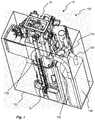
- FIG. 2 an embodiment of a liquid dosing unit 100 is shown.
- An outlet valve 130 is arranged at the lower part of the flushing system 10 and is connected to the dosing piping 120, as will be described more in detail in conjunction with Fig. 3 .
- the outlet valve 130 When pressing the flush button 32 (see Fig. 1 ), the outlet valve 130 is opened to allow the water to flush out into the WC bowl (not shown).
- the outlet valve 130 may form part of the flushing mechanism 30, e.g. by means of an overflow pipe which is raised upon flushing for opening the valve 130.
- Fig. 3 a more detailed view of the liquid dosing unit 100 is shown where the dosing reservoir 190 is hidden to facilitate understanding.
- the dosing piping 120 has two open ends 140a, 140b that connects to the outlet valve 130 of the flushing system 10, at a position being subject to the water flow only when the outlet valve 130 is open.
- the two open ends (140a, 140b) are connected to a flushing pipe downstream the outlet valve 130.
- the two open ends (140a, 140b) should be connected to a piping which is dry and filled with air between flushing, and which is wet and filled with water upon flushing.
- FIG. 4 another embodiment of a liquid dosing unit 100 is shown, in which only one end 140a is connecting to the outlet valve 130, while the other open end 140b opens to the volume inside the cistern 20. Hence, detergent arranged in the dosing piping 120 will flow into the cistern 20 upon flushing.
- the dosing piping 120 comprises a water trap 110, a first hose 121 and a second hose 122.
- the water trap 110 is arranged at a position vertically above the open ends 140a, 140b, and forms a U-bend, or an M-shaped structure.
- the water trap 110 has two open ends which are connectable to one of the open ends 140a by means of the first hose 121 and to the other open end 140b by means of the second hose 122.
- the first hose 121 is connected to a first end of the water trap 110
- the second hose 121 is connected to a second end of the water trap 110.
- the water trap 110 has a third open end located in between the two opens ends which is connectable to the fluid channel 150.
- the first hose 121, the second hose 122 and the fluid channel 150 may all be formed by fluid transporting devices, e.g. flexible hoses.
- the water trap 110 further comprises a vent device 160 arranged to act as an equalizer of the air pressure, as will be described more in detail in conjunction to Fig. 7 .
- the vent device 160 is arranged as an interface between the water trap 110 and the first hose 121.
- the function of the dosing piping 120 will now be described with reference to Fig. 6 to 8 .
- the neutral position, i.e. before a flush has been initiated, of the dosing piping 120 is shown in Fig. 6 .
- the water trap 110 is filled with detergent up to a level corresponding to the surrounding water level in the cistern, as is schematically shown in Fig. 6 . This is achieved due to the flexible shell of the dosing reservoir 190, pressing enclosed liquid to the same vertical level as the water level of the cistern 20.
- the replenishment of detergent into the water trap 110 occurs after every WC flush when the cistern (not shown) in the flushing system 10 is filling up with water. In this state, for the embodiment shown in Fig.
- the first hose 121 and the second hose 122 are filled with air since the connections are made to a dry environment downstream a sealing gasket of the outlet valve 130.
- the first hose 121 will be filled with water up to the water level of the cistern 20, while the second hose 122 will be filled with air since its connection is to the dry environment inside the outlet valve 130.
- Fig. 7 shows a schematic view of the dosing piping 120 after a flush has been initiated, i.e. when a user has initiated a flush.
- the outlet valve 130 is opened whereby water is starting to drain from the water cistern 20 out through the outlet valve 130.
- the first and second hose 121, 122 will thus be exposed to the water flow via the open ends 140a, 140b, and the hoses 121, 122 will be filled with water up to approximately the same vertical level as the water level inside the cistern 20.
- the remaining air is pressed upwards through the first and second hose 121, 122. Air entrapped in the first hose 121 of the dosing piping 120 will consequently flow out through the vent device 160.
- the height of the water column inside the hoses 121, 122 will be reduced accordingly until they are reaching an empty state.
- the water in the first hose 121 and the second hose 122 flows out, through the open ends 140a, 140b, into the outlet valve 130.
- the last water flushed into the toilet bowl is the water mixed with detergent, thus creating a fresh finish of the water that will stay in the WC suit until a next flush.
- Liquid detergent is in fact never dosed in the water while enclosed in the water cistern 20, and liquid detergent, which may be corrosive/abrasive, may consequently never be allowed to damage critical components inside the water cistern 20 such as gaskets etc. Further to this, since the dosing will occur at the end of the flushing sequence, a reduced volume of dosing will be required in order to clean the WC suit.
- the detergent will be pushed out from the first hose 121 and the associated open end 140b, into the water cistern 20.
- the detergent will reach the water of the cistern 20 rather immediately after initiating the flush, which means that the entire flushing will provide a cleaning action.
- the flushing water will expose the entire WC bowl to detergents, which means that the entire WC bowl will be cleaned.
- the dosing piping 220 comprises a water trap 210, a first hose 221 and a second hose 222.
- the water trap 210 is arranged at a position vertically above the open ends 140a, 140b.
- the water trap 210 has two open ends which are connectable to the first hose 221 and the second hose 222.
- the water trap 210 has a third open end located in between the two opens ends which is connectable to the tube 250.
- the first hose 221, the second hose 222 and the tube 250 may be formed by flexible hoses
- the water trap 210 forms an S-bend, whereby the first hose 221 and the second hose 222 are both arranged on the same side of the trap.
- the water trap 210 comprises a vent device 260 arranged to act as an equalizer of the air pressure.
- the function of the dosing piping 220 is the same as has been described above according to the embodiments of Figs. 5-8 .
Landscapes
- Health & Medical Sciences (AREA)
- Public Health (AREA)
- Epidemiology (AREA)
- Life Sciences & Earth Sciences (AREA)
- Engineering & Computer Science (AREA)
- Hydrology & Water Resources (AREA)
- Water Supply & Treatment (AREA)
- Sanitary Device For Flush Toilet (AREA)
Claims (9)
- Flüssigkeitsdosiereinheit zum Versorgen einer WC-Anlage mit Spülmittel, wobei die Flüssigkeitsdosiereinheit Folgendes umfasst:eine Dosierrohrleitung (120, 220) mit zwei offenen Enden (140a, 140b), die beide über einen ersten Schlauch (121, 221) und einen zweiten Schlauch (122, 222) mit einem Auslassventil (130) der in Benutzung stehenden WC-Anlage verbunden ist,wobei die Flüssigkeitsdosiereinheit ferner einen Wasserverschluss (110, 210) umfasst, der zwischen den beiden offenen Enden (140a, 140b) angeordnet ist an einer Position, die vertikal über den offenen Enden (140a, 140b) ist, wobeider Wasserverschluss (110, 210) der Dosierrohrleitung (120, 220) dazu ausgestaltet ist, Spülmittel einzuschließen, und wobei, wenn das Auslassventil (130) zum Spülen der WC-Anlage geöffnet ist, der erste Schlauch (121, 221) und der zweite Schlauch (122, 222) mit Wasser gefüllt werden bis zu ungefähr dem gleichen Wasserstand wie der Wasserstand innerhalb eines Spülkastens (20) der WC-Anlage, und verbleibende Luft durch den ersten Schlauch (121, 221) und den zweiten Schlauch (122, 222) derart nach oben gedrückt wird, dass im zweiten Schlauch (122, 222) gefangene Luft am Wasserverschluss (110, 210) angeordnetes Spülmittel zum wassergefüllten ersten Schlauch (121, 221) schiebt, wodurch aus dem Spülmittel mit dem darin bereitgestellten Wasser eine Mischung gebildet wird, die dann durch das mit dem ersten Schlauch (121, 222) verbundene Ende (140a) ausfließt in das Auslassventil (130) hinein, dadurch gekennzeichnet, dass der erste Schlauch (121, 122) mittels einer Ventilvorrichtung (160, 260) mit einem ersten Ende des Wasserverschlusses (110, 210) verbunden ist.
- Flüssigkeitsdosiereinheit nach Anspruch 1, wobei der zweite Schlauch (122, 222) mit einem zweiten Ende des Wasserverschlusses (110, 210) verbunden ist.
- Flüssigkeitsdosiereinheit nach Anspruch 1, wobei die Ventilvorrichtung (160, 260) einen Teil eines Trichters ausbildet.
- Dosiereinheit nach einem der vorangehenden Ansprüche, wobei das Auslassventil (130) mit dem Spülkasten (20) verbunden ist, der Spülwasser einschließt.
- Dosiereinheit nach einem der vorangehenden Ansprüche, ferner umfassend einen Dosierbehälter (190), der Spülmittel einschließt, wobei der Dosierbehälter (190) mit dem Wasserverschluss (110, 210) der Dosierrohrleitung (120, 220) verbunden ist, um Spülmittel vom Dosierbehälter (190) in den Wasserverschluss (110, 210) fließen zu lassen.
- Flüssigkeitsdosiereinheit nach Anspruch 5, wobei der Dosierbehälter (190) mittels eines Fluidkanals (150, 250) mit dem Wasserverschluss (110, 210) verbunden ist.
- Flüssigkeitsdosiereinheit nach Anspruch 5 oder 6, wobei der Dosierbehälter (190) eine Außenhülle aufweist, die ein flexibles Material umfasst.
- Flüssigkeitsdosiereinheit nach einem der Ansprüche 5 bis 7, wobei der Dosierbehälter (190) vertikal unterhalb des Wasserverschlusses (110, 210) angeordnet ist.
- WC-Anlage, umfassend eine Flüssigkeitsdosiereinheit nach einem der Ansprüche 1-8.
Applications Claiming Priority (1)
| Application Number | Priority Date | Filing Date | Title |
|---|---|---|---|
| SE1450777 | 2014-06-23 |
Publications (2)
| Publication Number | Publication Date |
|---|---|
| EP2960385A1 EP2960385A1 (de) | 2015-12-30 |
| EP2960385B1 true EP2960385B1 (de) | 2019-11-06 |
Family
ID=53496455
Family Applications (1)
| Application Number | Title | Priority Date | Filing Date |
|---|---|---|---|
| EP15173310.2A Active EP2960385B1 (de) | 2014-06-23 | 2015-06-23 | Flüssigkeitsdosiereinheit für ein toilettenspülsystem |
Country Status (1)
| Country | Link |
|---|---|
| EP (1) | EP2960385B1 (de) |
Families Citing this family (1)
| Publication number | Priority date | Publication date | Assignee | Title |
|---|---|---|---|---|
| GR20210100112A (el) * | 2021-02-24 | 2022-09-06 | Νεκταριος Παναγιωτη Ταλιαδουρος | Αυτοματη συσκευη απολυμανσης τουαλετας |
Family Cites Families (6)
| Publication number | Priority date | Publication date | Assignee | Title |
|---|---|---|---|---|
| GB211271A (en) * | 1922-12-04 | 1924-02-21 | Joseph Beaumont Butler | Improvements in and relating to disinfecting apparatus for water-closet pans, gullies and the like |
| US2479842A (en) * | 1947-02-20 | 1949-08-23 | John D Kirwan | Means for sterilizing flush type toilet bowls |
| US2812119A (en) * | 1954-09-20 | 1957-11-05 | James N Bethune | Pressure responsive automatic dispensing device |
| US20050178438A1 (en) * | 2004-02-18 | 2005-08-18 | Renner Brian K. | Flexible and extendable plumbing trap device |
| PT1756372E (pt) | 2004-05-05 | 2011-03-01 | Stefan Danielsson Spogardh | Dispositivo doseador para uma sanita |
| ITMI20121418A1 (it) | 2012-08-08 | 2014-02-09 | Oliveira & Irmao Sa | Dispositivo erogatore di un liquido di servizio per una cassetta di risciacquo |
-
2015
- 2015-06-23 EP EP15173310.2A patent/EP2960385B1/de active Active
Non-Patent Citations (1)
| Title |
|---|
| None * |
Also Published As
| Publication number | Publication date |
|---|---|
| EP2960385A1 (de) | 2015-12-30 |
Similar Documents
| Publication | Publication Date | Title |
|---|---|---|
| US9869080B2 (en) | Cleaning liquid dispenser | |
| KR20120086245A (ko) | 제트 동력식 변기 배수 시스템 | |
| EP2434064A1 (de) | Automatische Spendervorrichtung mit Dosierpumpe mit einstellbarem Volumen | |
| US8904571B2 (en) | Fresh flush recycling toilet | |
| EA039580B1 (ru) | Устройство для туалетов | |
| EA038271B1 (ru) | Сливной узел, санитарно-техническое изделие, содержащее такой узел, и способ промывки чаши такого санитарно-технического изделия | |
| EP2696003A1 (de) | Spülkastenbetriebsflüssigkeitspendervorrichtung | |
| WO2009143392A1 (en) | Water conservation system | |
| EP2960385B1 (de) | Flüssigkeitsdosiereinheit für ein toilettenspülsystem | |
| US9695583B2 (en) | Flush toilet with build-in one-way valve system for use in unclogging clogs and for efficient water-saving flush operations and related methods | |
| US8359679B2 (en) | Toilet clog removal and cleaning system | |
| CN104712040B (zh) | 一种可控制液体分离装置 | |
| EP2207938B1 (de) | Verbesserung von sanitären anlagen und diese betreffend | |
| EP3114286B1 (de) | Sanitärvorrichtung umfassend eine abgabevorrichtung | |
| KR200480074Y1 (ko) | 양변기용 세정액 자동 배출장치 | |
| WO2013123194A1 (en) | High pressure low liquid volume waste disposal system | |
| EP3009572B1 (de) | Spülsystem für eine toilette | |
| CN103882925A (zh) | 一种带延时抽气关闭系统的真空辅助抽水马桶 | |
| US8484769B1 (en) | System for delivering chemicals to a toilet bowl | |
| US20080302823A1 (en) | Coupling device and kit for a cleaning fluid dispenser | |
| RU2610122C2 (ru) | Дозирующее устройство вспомогательной жидкости для смывного бачка и смывной бачок, содержащий такое дозирующее устройство | |
| JP6505005B2 (ja) | 貯水槽の洗浄方法および施工方法 | |
| EP3219863B1 (de) | Wc | |
| CN105649162A (zh) | 防溅水的排便器 | |
| GB2466924A (en) | Liquid dispenser and flexible container arrangement for use in a cistern |
Legal Events
| Date | Code | Title | Description |
|---|---|---|---|
| PUAI | Public reference made under article 153(3) epc to a published international application that has entered the european phase |
Free format text: ORIGINAL CODE: 0009012 |
|
| AK | Designated contracting states |
Kind code of ref document: A1 Designated state(s): AL AT BE BG CH CY CZ DE DK EE ES FI FR GB GR HR HU IE IS IT LI LT LU LV MC MK MT NL NO PL PT RO RS SE SI SK SM TR |
|
| AX | Request for extension of the european patent |
Extension state: BA ME |
|
| 17P | Request for examination filed |
Effective date: 20160630 |
|
| RBV | Designated contracting states (corrected) |
Designated state(s): AL AT BE BG CH CY CZ DE DK EE ES FI FR GB GR HR HU IE IS IT LI LT LU LV MC MK MT NL NO PL PT RO RS SE SI SK SM TR |
|
| RAP1 | Party data changed (applicant data changed or rights of an application transferred) |
Owner name: GEBERIT INTERNATIONAL AG |
|
| STAA | Information on the status of an ep patent application or granted ep patent |
Free format text: STATUS: EXAMINATION IS IN PROGRESS |
|
| 17Q | First examination report despatched |
Effective date: 20181129 |
|
| GRAP | Despatch of communication of intention to grant a patent |
Free format text: ORIGINAL CODE: EPIDOSNIGR1 |
|
| STAA | Information on the status of an ep patent application or granted ep patent |
Free format text: STATUS: GRANT OF PATENT IS INTENDED |
|
| INTG | Intention to grant announced |
Effective date: 20190531 |
|
| GRAS | Grant fee paid |
Free format text: ORIGINAL CODE: EPIDOSNIGR3 |
|
| GRAA | (expected) grant |
Free format text: ORIGINAL CODE: 0009210 |
|
| STAA | Information on the status of an ep patent application or granted ep patent |
Free format text: STATUS: THE PATENT HAS BEEN GRANTED |
|
| AK | Designated contracting states |
Kind code of ref document: B1 Designated state(s): AL AT BE BG CH CY CZ DE DK EE ES FI FR GB GR HR HU IE IS IT LI LT LU LV MC MK MT NL NO PL PT RO RS SE SI SK SM TR |
|
| REG | Reference to a national code |
Ref country code: GB Ref legal event code: FG4D |
|
| REG | Reference to a national code |
Ref country code: CH Ref legal event code: EP Ref country code: AT Ref legal event code: REF Ref document number: 1198902 Country of ref document: AT Kind code of ref document: T Effective date: 20191115 |
|
| REG | Reference to a national code |
Ref country code: DE Ref legal event code: R096 Ref document number: 602015040967 Country of ref document: DE |
|
| REG | Reference to a national code |
Ref country code: IE Ref legal event code: FG4D |
|
| REG | Reference to a national code |
Ref country code: FI Ref legal event code: FGE |
|
| REG | Reference to a national code |
Ref country code: SE Ref legal event code: TRGR |
|
| REG | Reference to a national code |
Ref country code: NL Ref legal event code: MP Effective date: 20191106 |
|
| REG | Reference to a national code |
Ref country code: NO Ref legal event code: T2 Effective date: 20191106 |
|
| REG | Reference to a national code |
Ref country code: LT Ref legal event code: MG4D |
|
| PG25 | Lapsed in a contracting state [announced via postgrant information from national office to epo] |
Ref country code: BG Free format text: LAPSE BECAUSE OF FAILURE TO SUBMIT A TRANSLATION OF THE DESCRIPTION OR TO PAY THE FEE WITHIN THE PRESCRIBED TIME-LIMIT Effective date: 20200206 Ref country code: GR Free format text: LAPSE BECAUSE OF FAILURE TO SUBMIT A TRANSLATION OF THE DESCRIPTION OR TO PAY THE FEE WITHIN THE PRESCRIBED TIME-LIMIT Effective date: 20200207 Ref country code: LT Free format text: LAPSE BECAUSE OF FAILURE TO SUBMIT A TRANSLATION OF THE DESCRIPTION OR TO PAY THE FEE WITHIN THE PRESCRIBED TIME-LIMIT Effective date: 20191106 Ref country code: NL Free format text: LAPSE BECAUSE OF FAILURE TO SUBMIT A TRANSLATION OF THE DESCRIPTION OR TO PAY THE FEE WITHIN THE PRESCRIBED TIME-LIMIT Effective date: 20191106 Ref country code: PL Free format text: LAPSE BECAUSE OF FAILURE TO SUBMIT A TRANSLATION OF THE DESCRIPTION OR TO PAY THE FEE WITHIN THE PRESCRIBED TIME-LIMIT Effective date: 20191106 Ref country code: PT Free format text: LAPSE BECAUSE OF FAILURE TO SUBMIT A TRANSLATION OF THE DESCRIPTION OR TO PAY THE FEE WITHIN THE PRESCRIBED TIME-LIMIT Effective date: 20200306 Ref country code: LV Free format text: LAPSE BECAUSE OF FAILURE TO SUBMIT A TRANSLATION OF THE DESCRIPTION OR TO PAY THE FEE WITHIN THE PRESCRIBED TIME-LIMIT Effective date: 20191106 |
|
| PG25 | Lapsed in a contracting state [announced via postgrant information from national office to epo] |
Ref country code: IS Free format text: LAPSE BECAUSE OF FAILURE TO SUBMIT A TRANSLATION OF THE DESCRIPTION OR TO PAY THE FEE WITHIN THE PRESCRIBED TIME-LIMIT Effective date: 20200306 Ref country code: RS Free format text: LAPSE BECAUSE OF FAILURE TO SUBMIT A TRANSLATION OF THE DESCRIPTION OR TO PAY THE FEE WITHIN THE PRESCRIBED TIME-LIMIT Effective date: 20191106 Ref country code: HR Free format text: LAPSE BECAUSE OF FAILURE TO SUBMIT A TRANSLATION OF THE DESCRIPTION OR TO PAY THE FEE WITHIN THE PRESCRIBED TIME-LIMIT Effective date: 20191106 |
|
| PG25 | Lapsed in a contracting state [announced via postgrant information from national office to epo] |
Ref country code: AL Free format text: LAPSE BECAUSE OF FAILURE TO SUBMIT A TRANSLATION OF THE DESCRIPTION OR TO PAY THE FEE WITHIN THE PRESCRIBED TIME-LIMIT Effective date: 20191106 |
|
| PG25 | Lapsed in a contracting state [announced via postgrant information from national office to epo] |
Ref country code: DK Free format text: LAPSE BECAUSE OF FAILURE TO SUBMIT A TRANSLATION OF THE DESCRIPTION OR TO PAY THE FEE WITHIN THE PRESCRIBED TIME-LIMIT Effective date: 20191106 Ref country code: ES Free format text: LAPSE BECAUSE OF FAILURE TO SUBMIT A TRANSLATION OF THE DESCRIPTION OR TO PAY THE FEE WITHIN THE PRESCRIBED TIME-LIMIT Effective date: 20191106 Ref country code: RO Free format text: LAPSE BECAUSE OF FAILURE TO SUBMIT A TRANSLATION OF THE DESCRIPTION OR TO PAY THE FEE WITHIN THE PRESCRIBED TIME-LIMIT Effective date: 20191106 Ref country code: CZ Free format text: LAPSE BECAUSE OF FAILURE TO SUBMIT A TRANSLATION OF THE DESCRIPTION OR TO PAY THE FEE WITHIN THE PRESCRIBED TIME-LIMIT Effective date: 20191106 Ref country code: EE Free format text: LAPSE BECAUSE OF FAILURE TO SUBMIT A TRANSLATION OF THE DESCRIPTION OR TO PAY THE FEE WITHIN THE PRESCRIBED TIME-LIMIT Effective date: 20191106 |
|
| REG | Reference to a national code |
Ref country code: DE Ref legal event code: R097 Ref document number: 602015040967 Country of ref document: DE |
|
| REG | Reference to a national code |
Ref country code: AT Ref legal event code: MK05 Ref document number: 1198902 Country of ref document: AT Kind code of ref document: T Effective date: 20191106 |
|
| PG25 | Lapsed in a contracting state [announced via postgrant information from national office to epo] |
Ref country code: SK Free format text: LAPSE BECAUSE OF FAILURE TO SUBMIT A TRANSLATION OF THE DESCRIPTION OR TO PAY THE FEE WITHIN THE PRESCRIBED TIME-LIMIT Effective date: 20191106 Ref country code: SM Free format text: LAPSE BECAUSE OF FAILURE TO SUBMIT A TRANSLATION OF THE DESCRIPTION OR TO PAY THE FEE WITHIN THE PRESCRIBED TIME-LIMIT Effective date: 20191106 |
|
| PLBE | No opposition filed within time limit |
Free format text: ORIGINAL CODE: 0009261 |
|
| STAA | Information on the status of an ep patent application or granted ep patent |
Free format text: STATUS: NO OPPOSITION FILED WITHIN TIME LIMIT |
|
| 26N | No opposition filed |
Effective date: 20200807 |
|
| PG25 | Lapsed in a contracting state [announced via postgrant information from national office to epo] |
Ref country code: SI Free format text: LAPSE BECAUSE OF FAILURE TO SUBMIT A TRANSLATION OF THE DESCRIPTION OR TO PAY THE FEE WITHIN THE PRESCRIBED TIME-LIMIT Effective date: 20191106 Ref country code: AT Free format text: LAPSE BECAUSE OF FAILURE TO SUBMIT A TRANSLATION OF THE DESCRIPTION OR TO PAY THE FEE WITHIN THE PRESCRIBED TIME-LIMIT Effective date: 20191106 |
|
| REG | Reference to a national code |
Ref country code: DE Ref legal event code: R119 Ref document number: 602015040967 Country of ref document: DE |
|
| PG25 | Lapsed in a contracting state [announced via postgrant information from national office to epo] |
Ref country code: MC Free format text: LAPSE BECAUSE OF FAILURE TO SUBMIT A TRANSLATION OF THE DESCRIPTION OR TO PAY THE FEE WITHIN THE PRESCRIBED TIME-LIMIT Effective date: 20191106 Ref country code: IT Free format text: LAPSE BECAUSE OF FAILURE TO SUBMIT A TRANSLATION OF THE DESCRIPTION OR TO PAY THE FEE WITHIN THE PRESCRIBED TIME-LIMIT Effective date: 20191106 |
|
| REG | Reference to a national code |
Ref country code: CH Ref legal event code: PL |
|
| GBPC | Gb: european patent ceased through non-payment of renewal fee |
Effective date: 20200623 |
|
| PG25 | Lapsed in a contracting state [announced via postgrant information from national office to epo] |
Ref country code: LU Free format text: LAPSE BECAUSE OF NON-PAYMENT OF DUE FEES Effective date: 20200623 |
|
| REG | Reference to a national code |
Ref country code: BE Ref legal event code: MM Effective date: 20200630 |
|
| PG25 | Lapsed in a contracting state [announced via postgrant information from national office to epo] |
Ref country code: IE Free format text: LAPSE BECAUSE OF NON-PAYMENT OF DUE FEES Effective date: 20200623 Ref country code: GB Free format text: LAPSE BECAUSE OF NON-PAYMENT OF DUE FEES Effective date: 20200623 Ref country code: CH Free format text: LAPSE BECAUSE OF NON-PAYMENT OF DUE FEES Effective date: 20200630 Ref country code: LI Free format text: LAPSE BECAUSE OF NON-PAYMENT OF DUE FEES Effective date: 20200630 Ref country code: FR Free format text: LAPSE BECAUSE OF NON-PAYMENT OF DUE FEES Effective date: 20200630 |
|
| PG25 | Lapsed in a contracting state [announced via postgrant information from national office to epo] |
Ref country code: BE Free format text: LAPSE BECAUSE OF NON-PAYMENT OF DUE FEES Effective date: 20200630 Ref country code: DE Free format text: LAPSE BECAUSE OF NON-PAYMENT OF DUE FEES Effective date: 20210101 |
|
| PG25 | Lapsed in a contracting state [announced via postgrant information from national office to epo] |
Ref country code: TR Free format text: LAPSE BECAUSE OF FAILURE TO SUBMIT A TRANSLATION OF THE DESCRIPTION OR TO PAY THE FEE WITHIN THE PRESCRIBED TIME-LIMIT Effective date: 20191106 Ref country code: MT Free format text: LAPSE BECAUSE OF FAILURE TO SUBMIT A TRANSLATION OF THE DESCRIPTION OR TO PAY THE FEE WITHIN THE PRESCRIBED TIME-LIMIT Effective date: 20191106 Ref country code: CY Free format text: LAPSE BECAUSE OF FAILURE TO SUBMIT A TRANSLATION OF THE DESCRIPTION OR TO PAY THE FEE WITHIN THE PRESCRIBED TIME-LIMIT Effective date: 20191106 |
|
| PG25 | Lapsed in a contracting state [announced via postgrant information from national office to epo] |
Ref country code: MK Free format text: LAPSE BECAUSE OF FAILURE TO SUBMIT A TRANSLATION OF THE DESCRIPTION OR TO PAY THE FEE WITHIN THE PRESCRIBED TIME-LIMIT Effective date: 20191106 |
|
| PGFP | Annual fee paid to national office [announced via postgrant information from national office to epo] |
Ref country code: FI Payment date: 20250616 Year of fee payment: 11 |
|
| PGFP | Annual fee paid to national office [announced via postgrant information from national office to epo] |
Ref country code: NO Payment date: 20250611 Year of fee payment: 11 |
|
| PGFP | Annual fee paid to national office [announced via postgrant information from national office to epo] |
Ref country code: SE Payment date: 20250610 Year of fee payment: 11 |