EP2960403A1 - Douille de sol - Google Patents
Douille de sol Download PDFInfo
- Publication number
- EP2960403A1 EP2960403A1 EP15164290.7A EP15164290A EP2960403A1 EP 2960403 A1 EP2960403 A1 EP 2960403A1 EP 15164290 A EP15164290 A EP 15164290A EP 2960403 A1 EP2960403 A1 EP 2960403A1
- Authority
- EP
- European Patent Office
- Prior art keywords
- receiving
- insert
- base body
- ground
- housing
- Prior art date
- Legal status (The legal status is an assumption and is not a legal conclusion. Google has not performed a legal analysis and makes no representation as to the accuracy of the status listed.)
- Withdrawn
Links
Images

Classifications
-
- E—FIXED CONSTRUCTIONS
- E05—LOCKS; KEYS; WINDOW OR DOOR FITTINGS; SAFES
- E05B—LOCKS; ACCESSORIES THEREFOR; HANDCUFFS
- E05B15/00—Other details of locks; Parts for engagement by bolts of fastening devices
- E05B15/02—Striking-plates; Keepers; Bolt staples; Escutcheons
- E05B15/0205—Striking-plates, keepers, staples
- E05B15/024—Striking-plates, keepers, staples adjustable
-
- E—FIXED CONSTRUCTIONS
- E05—LOCKS; KEYS; WINDOW OR DOOR FITTINGS; SAFES
- E05B—LOCKS; ACCESSORIES THEREFOR; HANDCUFFS
- E05B15/00—Other details of locks; Parts for engagement by bolts of fastening devices
- E05B15/02—Striking-plates; Keepers; Bolt staples; Escutcheons
- E05B15/0205—Striking-plates, keepers, staples
- E05B15/029—Closures, e.g. preventing dirt or paint from entering into the striker
-
- E—FIXED CONSTRUCTIONS
- E05—LOCKS; KEYS; WINDOW OR DOOR FITTINGS; SAFES
- E05C—BOLTS OR FASTENING DEVICES FOR WINGS, SPECIALLY FOR DOORS OR WINDOWS
- E05C9/00—Arrangements of simultaneously actuated bolts or other securing devices at well-separated positions on the same wing
- E05C9/18—Details of fastening means or of fixed retaining means for the ends of bars
- E05C9/1808—Keepers
-
- E—FIXED CONSTRUCTIONS
- E05—LOCKS; KEYS; WINDOW OR DOOR FITTINGS; SAFES
- E05B—LOCKS; ACCESSORIES THEREFOR; HANDCUFFS
- E05B63/00—Locks or fastenings with special structural characteristics
- E05B2063/0039—Ground mounted locks or lock elements
Definitions
- the present invention relates to a ground socket for receiving a closing or locking element of a floor lock or a floor lock of a door, a window, a sliding wall or the like.
- Ground sleeves of this type are embedded in the ground and serve to close or lock doors, windows, sliding walls or the like to receive a respective closing or locking element of the relevant floor lock or the relevant floor lock.
- the invention has for its object to provide a ground socket of the type mentioned above, which is suitable for the simplest possible handling universally applicable and in particular for receiving different dimensions closing or locking elements of different floor locks or floor locks.
- the ground socket serves to receive a closing or locking element of a floor lock or a floor lock of a door, a window, a sliding wall or the like and comprises a particular pot-like base body and a usable therein removable insert, on its two opposite end faces, each with a Receiving opening for receiving a locking or locking element is provided, wherein the receiving openings have different cross-sections and the removable insert is selectively inserted into the body so that either one end face with a receiving opening or the other end face with the other receiving opening for receiving a closing or locking element is arranged in the region of the top of the base body facing away from the bottom of the base body.
- the ground socket is extremely universally usable with extremely simple handling and also suitable for receiving different dimensions closing or locking elements of different floor locks or floor locks.
- the exchange insert is used in one or in a pivoted position by 180 ° in the main body, either the one or the other receiving opening comes to rest, so that the bottom sleeve for use of the respective dimensions having closing or Locking element is suitable.
- a change to a provided with respective other dimensions closing or locking element is in a simple manner possible in that the removable insert taken out of the recessed into the ground body and is used in a staggered by 180 ° position back into the body.
- the base body can be left in the ground.
- the different receiving openings of the exchange insert may for example each have a circular cross-section and have different diameters or have different cross-sectional shapes.
- the different design of the receiving openings can be taken into account in particular the fact that closing elements of floor locks often have larger dimensions than locking elements of floor locks.
- a preferred practical embodiment of the ground socket according to the invention is characterized in that at least one of the receiving openings of the exchange insert is arranged eccentrically to the central longitudinal axis of the exchange insert and / or the replacement insert receiving bore of the body eccentrically to the central axis of the body.
- the removable insert is provided with resiliently against the receiving openings held spring covers.
- a respective spring cover is resiliently held against the respective receiving opening, it can be moved away with the introduction of a respective closing or locking element for releasing the receiving opening in a simple manner against the spring force of the receiving opening. If the closing or locking element is pulled out again, the relevant receiving opening is automatically closed again.
- the exchange insert preferably comprises a sleeve-like housing in which the spring cover are guided displaceably parallel to the central longitudinal axis of the exchange insert, wherein the spring cover are held in particular by a spring arranged between these in opposite directions against the respective receiving opening.
- the sleeve-like housing of the removable insert is preferably provided in the region of its receiving openings in each case with an inner shoulder, against which the respective spring cover is held by the spring force.
- the spring cover are thus taken captive in relatively simple construction of the bottom sleeve in the housing of the removable insert.
- the interchangeable insert including the spring cover and the spring can be provided as a unit.
- the spring cover are each provided with a head portion which has a complementary cross-section of the respective receiving opening cross-section and protrudes to close the respective receiving opening in this.
- each of the circumferential groove in the region of the overhead end face of the removable insert can be provided with a corresponding elastic sealing and / or clamping ring, whereby on the one hand a sealing and vibration-free recording of the exchange insert is ensured in the body, on the other hand, however, easily take out the exchange insert for a respective Changing the receiving openings and / or a rotation of the removable insert is made possible relative to the main body.
- the embedded in the ground body can be supported in particular on the ground surface.
- a fastening screw can be passed.
- a fastening screw can for example be screwed into a recessed into the ground dowel, whereby the body is reliably fixed in the ground.
- the sleeve-like housing of the removable insert is made in two parts.
- the two housing parts of the removable insert may in particular be telescopically plugged together.
- the two housing parts of the removable insert are connected to one another via latching means.
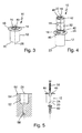
- Fig. 1 to 5 show a schematic representation of an exemplary embodiment of a ground socket 10 according to the invention for receiving a closing or locking element of a floor lock or a floor locking a door, a window, a sliding wall or the like.
- the bottom sleeve 10 comprises a pot-like basic body 12 and a removable insert 14 which can be inserted into it.
- the changeover insert 14 is provided on its two opposite end faces, each with a receiving opening 16 or 18 for receiving a closing or locking element.
- the receiving openings 16, 18 have different Cross-sections. In the present case, for example, they each have a circular cross section and different diameters. However, for example, receiving openings 16, 18 with different cross-sectional shapes are conceivable.
- the interchangeable insert 14 is optionally used in the base body 12 that either one end face with the one receiving opening 16 or the other end face with the other receiving opening 18 for receiving a closing or locking element in the region facing away from the bottom 20 of the base 12 top of the Base body 12 is arranged.
- At least one of the receiving openings 16, 18 of the interchangeable insert 14 can be eccentric to the central longitudinal axis 22 (FIG. Fig. 4 ) of the exchange insert 14 may be arranged. In the present case, both receiving openings 16, 18 are each arranged correspondingly eccentrically.
- the bore 14 of the base body 12 accommodating the changeover insert 12 can also be eccentric to the central longitudinal axis 26 (FIG. FIGS. 3 and 5 ) of the base 12 may be arranged.
- the removable insert 14 is provided with resilient against the receiving openings 16, 18 held spring covers 28, 30.
- the changeover insert 14 comprises a sleeve-like housing 32 in which the spring cover 28, 30 parallel to the central longitudinal axis 22 (FIG. Fig. 4 ) of the exchange insert 14 are guided displaceably.
- the sleeve-like housing 32 of the removable insert 14 in the region of its receiving openings 16, 18 each provided with an inner shoulder 36 and 38, against which the respective spring cover 28 and 30 is held by the spring force.
- the spring covers 28, 30 can be provided in the manner shown in each case with a head portion 40 which has a cross-section of the respective receiving opening 16 and 18 complementary cross-section and for closing the respective receiving opening 16 and 18 projects into it.
- a respective closing or locking element engaging in ground sleeve 10 results in at least substantially flush termination of the head portion 40 of a respective spring cover 28 and 30 with the respective outer face of the removable insert 14 and with this also a flush termination with the outer Front side of the main body 12 ( Fig. 3 ).
- the parallel to the central longitudinal axis 22 of the removable insert 14 slidably guided in the sleeve-like housing 32 of the removable insert 14 spring cover 28, 30 are in particular rotationally secured relative to the housing 32.
- the exchange insert 14 may be provided in the region of its two end faces in each case with a circumferential groove 42 into which an elastic sealing and / or clamping ring 44 can be inserted. As in Fig. 2 shown, such a sealing and / or clamping ring 44 can be mounted in particular in the provided in the region of the overhead end face of the removable insert 14 circumferential groove 42. This ensures, on the one hand, that the interchangeable insert 14 is received in the base body 14 in a sealing and vibration-free manner. On the other hand, the changeover insert 14 can be easily removed from the main body 12 for a respective change of the receiving opening 16 or 18.
- the main body 12 may be provided in the region of its inlet opening 46 with a radially outwardly extending collar 48. With such a collar, the main body 12 of the in the bottom 50 (FIG. Fig. 5 ) embedded ground sleeve, in particular on the surface of the bottom 50.
- the base body 12 For anchoring the base body 12 in the receptacle for receiving the bottom sleeve 10 in the bottom 50 receiving bore 52 (FIG. Fig. 5 ), the base body 12 may be provided in its bottom area with a passage opening 54 (FIG. Fig. 2 ), through which a fastening screw 56 (FIG. Fig. 5 ) can be passed.
- a dowel 60 may be introduced into which the fastening screw 56 can be screwed.
- any other types of attachment for anchoring the bottom sleeve 10 in the bottom 50 are conceivable.
- the central longitudinal axis 26 of the body 12 coincides with the central longitudinal axis 26 of the bore 58 following the receiving bore 52.
- the sleeve-like housing 32 of the removable insert 14 can, as best seen in the Fig. 1 can be seen, in particular be designed in two parts.
- the two housing parts 32 ', 32 "of the interchangeable insert 14 can be telescopically plugged together, for example Fig. 1 can be seen, the two housing parts 32 ', 32 "can be connected to each other via locking means.
- Fig. 4 shows the base body 12 and taken out of this removable insert 14 of the ground socket.
- Fig. 5 shows the inserted into the bottom 50 receiving bore 52 base body 12 of the bottom sleeve 10 and provided with the receiving bore 52 bottom portion 64 in a sectional view.
Landscapes
- Engineering & Computer Science (AREA)
- Mechanical Engineering (AREA)
- Dowels (AREA)
- Component Parts Of Construction Machinery (AREA)
Applications Claiming Priority (1)
| Application Number | Priority Date | Filing Date | Title |
|---|---|---|---|
| DE102014212362.3A DE102014212362B3 (de) | 2014-06-26 | 2014-06-26 | Bodenhülse |
Publications (1)
| Publication Number | Publication Date |
|---|---|
| EP2960403A1 true EP2960403A1 (fr) | 2015-12-30 |
Family
ID=51567784
Family Applications (1)
| Application Number | Title | Priority Date | Filing Date |
|---|---|---|---|
| EP15164290.7A Withdrawn EP2960403A1 (fr) | 2014-06-26 | 2015-04-20 | Douille de sol |
Country Status (3)
| Country | Link |
|---|---|
| EP (1) | EP2960403A1 (fr) |
| CN (1) | CN105298264B (fr) |
| DE (1) | DE102014212362B3 (fr) |
Families Citing this family (3)
| Publication number | Priority date | Publication date | Assignee | Title |
|---|---|---|---|---|
| DE102017100447C5 (de) | 2017-01-11 | 2022-10-27 | Dorma-Glas Gmbh | Buchsenanordnung für einen Lagerbolzen eines Türflügels |
| CN109972502B (zh) * | 2019-03-29 | 2020-08-28 | 齐鲁交通(济南)京沪高速公路有限公司 | 可调式橡胶支座及其安装方法、调节方法 |
| DE102020134110A1 (de) * | 2020-12-18 | 2022-06-23 | ABUS August Bremicker Söhne Kommanditgesellschaft | Zweiradschloss |
Citations (6)
| Publication number | Priority date | Publication date | Assignee | Title |
|---|---|---|---|---|
| FR1333904A (fr) * | 1962-06-21 | 1963-08-02 | Dispositif de gâche pour pêne de serrure | |
| JPS48104795U (fr) * | 1972-03-11 | 1973-12-06 | ||
| DE8029903U1 (de) * | 1980-11-08 | 1981-02-26 | Schueco Heinz Schuermann Gmbh & Co, 4800 Bielefeld | Vorrichtung zum festlegen einer einer zweifluegeligen drehtuer zugeordneten bodenhuelse |
| JPH09151631A (ja) * | 1995-11-22 | 1997-06-10 | Nishi Seisakusho:Kk | 上げ落とし錠 |
| KR200397191Y1 (ko) * | 2005-05-30 | 2005-09-30 | 박래주 | 잠금장치의 걸림쇠 수용장치 |
| KR100861138B1 (ko) * | 2008-03-27 | 2008-09-30 | 이예명 | 출입문 고정용 먼지막이소켓 |
Family Cites Families (3)
| Publication number | Priority date | Publication date | Assignee | Title |
|---|---|---|---|---|
| DE20109671U1 (de) * | 2001-06-12 | 2002-10-24 | Hüppe Form Raumtrennsysteme GmbH, 26133 Oldenburg | Verriegelung eines Trennwandelementes sowie ein Trennwandelement mit einer solchen Vorrichtung |
| CN2501960Y (zh) * | 2001-09-28 | 2002-07-24 | 陆津汉 | 防尘锁具 |
| US9222280B2 (en) * | 2010-06-23 | 2015-12-29 | Fire & Security Hardware Pty Ltd | Locking mechanism |
-
2014
- 2014-06-26 DE DE102014212362.3A patent/DE102014212362B3/de active Active
-
2015
- 2015-04-20 EP EP15164290.7A patent/EP2960403A1/fr not_active Withdrawn
- 2015-06-26 CN CN201510362040.5A patent/CN105298264B/zh active Active
Patent Citations (6)
| Publication number | Priority date | Publication date | Assignee | Title |
|---|---|---|---|---|
| FR1333904A (fr) * | 1962-06-21 | 1963-08-02 | Dispositif de gâche pour pêne de serrure | |
| JPS48104795U (fr) * | 1972-03-11 | 1973-12-06 | ||
| DE8029903U1 (de) * | 1980-11-08 | 1981-02-26 | Schueco Heinz Schuermann Gmbh & Co, 4800 Bielefeld | Vorrichtung zum festlegen einer einer zweifluegeligen drehtuer zugeordneten bodenhuelse |
| JPH09151631A (ja) * | 1995-11-22 | 1997-06-10 | Nishi Seisakusho:Kk | 上げ落とし錠 |
| KR200397191Y1 (ko) * | 2005-05-30 | 2005-09-30 | 박래주 | 잠금장치의 걸림쇠 수용장치 |
| KR100861138B1 (ko) * | 2008-03-27 | 2008-09-30 | 이예명 | 출입문 고정용 먼지막이소켓 |
Also Published As
| Publication number | Publication date |
|---|---|
| CN105298264A (zh) | 2016-02-03 |
| DE102014212362B3 (de) | 2014-10-09 |
| CN105298264B (zh) | 2017-07-28 |
Similar Documents
| Publication | Publication Date | Title |
|---|---|---|
| DE202005016046U1 (de) | Sanitäres Einbauteil | |
| EP2055867A1 (fr) | Poignée dotée d'une garniture de fermeture | |
| DE202007014504U1 (de) | Stangenverschluss mit hebelförmigem Stangenantrieb | |
| WO2009103414A1 (fr) | Pêne de sécurité | |
| DE102010062565A1 (de) | Winkelverstellbarer Handgriff für ein Handwerkzeug | |
| DE202008006612U1 (de) | Anschluss- und Verbindungsvorrichtung für Hochdruckleitungen | |
| DE202016101285U1 (de) | Vorrichtung zur Montage eines Möbelbeschlages | |
| EP2796645B1 (fr) | Serrure à pêne dormant d'un meuble | |
| DE102014212362B3 (de) | Bodenhülse | |
| DE102009014084A1 (de) | Scharnier für einen Kraftwagen | |
| EP3535824B1 (fr) | Support de jeu de barres et ensemble correspondant | |
| DE102009020994A1 (de) | Einzugvorrichtung | |
| DE102014112308B4 (de) | Exzentereinheit und Verbinder | |
| DE102014114580A1 (de) | Kraftfahrzeugtürverschluss | |
| DE202013002202U1 (de) | Behälterverschluss | |
| DE202010005777U1 (de) | Schnellmontage-Scharnier | |
| DE102011081917B4 (de) | Dämpfung für Hausgerätetüren | |
| DE202008014086U1 (de) | Dämpfungszylinder | |
| DE102013205061A1 (de) | Bedienungsmittel für eine Platte, Kombination zweier Bedienungsmittel und Verfahren zum klemmfesten Positionieren des Bedienungsmittels an einer Platte | |
| CH709435B1 (de) | Einsteckschloss für einen Flügel einer Tür oder eines Fensters. | |
| EP2476814A2 (fr) | Dispositif de fermeture de sol, notamment escalier de grenier doté d'une charnière en matière synthétique | |
| EP3565991A1 (fr) | Ensemble soupape | |
| DE102008030959A1 (de) | Montageverbindung mit Federelement für Handhabe | |
| DE102007060439A1 (de) | Türgriff, insbesondere von Türen von Öfen zum Kochen von Lebensmitteln | |
| DE10343928B3 (de) | Ausstellfeder |
Legal Events
| Date | Code | Title | Description |
|---|---|---|---|
| PUAI | Public reference made under article 153(3) epc to a published international application that has entered the european phase |
Free format text: ORIGINAL CODE: 0009012 |
|
| AK | Designated contracting states |
Kind code of ref document: A1 Designated state(s): AL AT BE BG CH CY CZ DE DK EE ES FI FR GB GR HR HU IE IS IT LI LT LU LV MC MK MT NL NO PL PT RO RS SE SI SK SM TR |
|
| AX | Request for extension of the european patent |
Extension state: BA ME |
|
| 17P | Request for examination filed |
Effective date: 20160622 |
|
| RBV | Designated contracting states (corrected) |
Designated state(s): AL AT BE BG CH CY CZ DE DK EE ES FI FR GB GR HR HU IE IS IT LI LT LU LV MC MK MT NL NO PL PT RO RS SE SI SK SM TR |
|
| GRAP | Despatch of communication of intention to grant a patent |
Free format text: ORIGINAL CODE: EPIDOSNIGR1 |
|
| INTG | Intention to grant announced |
Effective date: 20170627 |
|
| STAA | Information on the status of an ep patent application or granted ep patent |
Free format text: STATUS: THE APPLICATION HAS BEEN WITHDRAWN |
|
| 18W | Application withdrawn |
Effective date: 20170804 |