EP2960450A2 - Système d'échappement pour moteurs à combustion interne - Google Patents
Système d'échappement pour moteurs à combustion interne Download PDFInfo
- Publication number
- EP2960450A2 EP2960450A2 EP15000201.2A EP15000201A EP2960450A2 EP 2960450 A2 EP2960450 A2 EP 2960450A2 EP 15000201 A EP15000201 A EP 15000201A EP 2960450 A2 EP2960450 A2 EP 2960450A2
- Authority
- EP
- European Patent Office
- Prior art keywords
- rupture
- bursting
- exhaust gas
- rupture disk
- exhaust
- Prior art date
- Legal status (The legal status is an assumption and is not a legal conclusion. Google has not performed a legal analysis and makes no representation as to the accuracy of the status listed.)
- Granted
Links
Images

Classifications
-
- F—MECHANICAL ENGINEERING; LIGHTING; HEATING; WEAPONS; BLASTING
- F01—MACHINES OR ENGINES IN GENERAL; ENGINE PLANTS IN GENERAL; STEAM ENGINES
- F01N—GAS-FLOW SILENCERS OR EXHAUST APPARATUS FOR MACHINES OR ENGINES IN GENERAL; GAS-FLOW SILENCERS OR EXHAUST APPARATUS FOR INTERNAL-COMBUSTION ENGINES
- F01N3/00—Exhaust or silencing apparatus having means for purifying, rendering innocuous, or otherwise treating exhaust
- F01N3/02—Exhaust or silencing apparatus having means for purifying, rendering innocuous, or otherwise treating exhaust for cooling, or for removing solid constituents of, exhaust
- F01N3/021—Exhaust or silencing apparatus having means for purifying, rendering innocuous, or otherwise treating exhaust for cooling, or for removing solid constituents of, exhaust by means of filters
- F01N3/031—Exhaust or silencing apparatus having means for purifying, rendering innocuous, or otherwise treating exhaust for cooling, or for removing solid constituents of, exhaust by means of filters having means for by-passing filters, e.g. when clogged or during cold engine start
-
- B—PERFORMING OPERATIONS; TRANSPORTING
- B01—PHYSICAL OR CHEMICAL PROCESSES OR APPARATUS IN GENERAL
- B01D—SEPARATION
- B01D46/00—Filters or filtering processes specially modified for separating dispersed particles from gases or vapours
- B01D46/0084—Filters or filtering processes specially modified for separating dispersed particles from gases or vapours provided with safety means
- B01D46/0087—Bypass or safety valves
-
- F—MECHANICAL ENGINEERING; LIGHTING; HEATING; WEAPONS; BLASTING
- F01—MACHINES OR ENGINES IN GENERAL; ENGINE PLANTS IN GENERAL; STEAM ENGINES
- F01N—GAS-FLOW SILENCERS OR EXHAUST APPARATUS FOR MACHINES OR ENGINES IN GENERAL; GAS-FLOW SILENCERS OR EXHAUST APPARATUS FOR INTERNAL-COMBUSTION ENGINES
- F01N2260/00—Exhaust treating devices having provisions not otherwise provided for
- F01N2260/06—Exhaust treating devices having provisions not otherwise provided for for improving exhaust evacuation or circulation, or reducing back-pressure
-
- F—MECHANICAL ENGINEERING; LIGHTING; HEATING; WEAPONS; BLASTING
- F01—MACHINES OR ENGINES IN GENERAL; ENGINE PLANTS IN GENERAL; STEAM ENGINES
- F01N—GAS-FLOW SILENCERS OR EXHAUST APPARATUS FOR MACHINES OR ENGINES IN GENERAL; GAS-FLOW SILENCERS OR EXHAUST APPARATUS FOR INTERNAL-COMBUSTION ENGINES
- F01N2410/00—By-passing, at least partially, exhaust from inlet to outlet of apparatus, to atmosphere or to other device
-
- F—MECHANICAL ENGINEERING; LIGHTING; HEATING; WEAPONS; BLASTING
- F01—MACHINES OR ENGINES IN GENERAL; ENGINE PLANTS IN GENERAL; STEAM ENGINES
- F01N—GAS-FLOW SILENCERS OR EXHAUST APPARATUS FOR MACHINES OR ENGINES IN GENERAL; GAS-FLOW SILENCERS OR EXHAUST APPARATUS FOR INTERNAL-COMBUSTION ENGINES
- F01N2410/00—By-passing, at least partially, exhaust from inlet to outlet of apparatus, to atmosphere or to other device
- F01N2410/08—By-passing, at least partially, exhaust from inlet to outlet of apparatus, to atmosphere or to other device in case of clogging, e.g. of particle filter
-
- F—MECHANICAL ENGINEERING; LIGHTING; HEATING; WEAPONS; BLASTING
- F01—MACHINES OR ENGINES IN GENERAL; ENGINE PLANTS IN GENERAL; STEAM ENGINES
- F01N—GAS-FLOW SILENCERS OR EXHAUST APPARATUS FOR MACHINES OR ENGINES IN GENERAL; GAS-FLOW SILENCERS OR EXHAUST APPARATUS FOR INTERNAL-COMBUSTION ENGINES
- F01N2410/00—By-passing, at least partially, exhaust from inlet to outlet of apparatus, to atmosphere or to other device
- F01N2410/14—By-passing, at least partially, exhaust from inlet to outlet of apparatus, to atmosphere or to other device in case of excessive pressure, e.g. using a safety valve
-
- F—MECHANICAL ENGINEERING; LIGHTING; HEATING; WEAPONS; BLASTING
- F01—MACHINES OR ENGINES IN GENERAL; ENGINE PLANTS IN GENERAL; STEAM ENGINES
- F01N—GAS-FLOW SILENCERS OR EXHAUST APPARATUS FOR MACHINES OR ENGINES IN GENERAL; GAS-FLOW SILENCERS OR EXHAUST APPARATUS FOR INTERNAL-COMBUSTION ENGINES
- F01N2590/00—Exhaust or silencing apparatus adapted to particular use, e.g. for military applications, airplanes, submarines
- F01N2590/02—Exhaust or silencing apparatus adapted to particular use, e.g. for military applications, airplanes, submarines for marine vessels or naval applications
-
- F—MECHANICAL ENGINEERING; LIGHTING; HEATING; WEAPONS; BLASTING
- F01—MACHINES OR ENGINES IN GENERAL; ENGINE PLANTS IN GENERAL; STEAM ENGINES
- F01N—GAS-FLOW SILENCERS OR EXHAUST APPARATUS FOR MACHINES OR ENGINES IN GENERAL; GAS-FLOW SILENCERS OR EXHAUST APPARATUS FOR INTERNAL-COMBUSTION ENGINES
- F01N2590/00—Exhaust or silencing apparatus adapted to particular use, e.g. for military applications, airplanes, submarines
- F01N2590/08—Exhaust or silencing apparatus adapted to particular use, e.g. for military applications, airplanes, submarines for heavy duty applications, e.g. trucks, buses, tractors, locomotives
-
- Y—GENERAL TAGGING OF NEW TECHNOLOGICAL DEVELOPMENTS; GENERAL TAGGING OF CROSS-SECTIONAL TECHNOLOGIES SPANNING OVER SEVERAL SECTIONS OF THE IPC; TECHNICAL SUBJECTS COVERED BY FORMER USPC CROSS-REFERENCE ART COLLECTIONS [XRACs] AND DIGESTS
- Y02—TECHNOLOGIES OR APPLICATIONS FOR MITIGATION OR ADAPTATION AGAINST CLIMATE CHANGE
- Y02T—CLIMATE CHANGE MITIGATION TECHNOLOGIES RELATED TO TRANSPORTATION
- Y02T10/00—Road transport of goods or passengers
- Y02T10/10—Internal combustion engine [ICE] based vehicles
- Y02T10/12—Improving ICE efficiencies
Definitions
- the invention relates to an exhaust system for internal combustion engines according to the preamble of claim 1 and of claim 12.
- Such exhaust-gas purification devices for the after-treatment of the exhaust gas may be, for example, particulate filters, SCR catalysts, etc.
- exhaust gas aftertreatment is also required for engines used in ships, for example in the form of particulate filters, SCR catalysts for NOx reduction and DeSOx systems.
- shut-off devices in the form of exhaust valves or A bgasschiebern be used.
- a bgasschiebern In order to open the bypass line usually shut-off devices in the form of exhaust valves or A bgasschiebern be used.
- shut-off devices in the form of exhaust valves or A bgasschiebern be used.
- a bgasschiebern In order to open the bypass line usually shut-off devices in the form of exhaust valves or A bgasschiebern be used.
- a bgasschiebern In order to open the bypass line usually shut-off devices in the form of exhaust valves or A bgasschiebern be used.
- most of an air purge on the shaft passages of the exhaust flap is provided to avoid exhaust gas leakage into the environment z u. This leads to a relatively high apparive expense and high investment and operating costs, since permanent compressed air must be provided.
- an exhaust system for internal combustion engines which has a Abgasleit tion, in which at least ei ne exhaust gas purification device (for example, a particle filter, a SCR catalysato r and / or a DeSO x system, etc.) is arranged.
- ei ne exhaust gas purification device for example, a particle filter, a SCR catalysato r and / or a DeSO x system, etc.
- the exhaust system at least egg nen parallel to the at least one Abgasre in Trents worn angeor dneten branch channel (for example, a branch of the upstream at least egg nen or upstream at least one exhaust purification device branching branch channel), in particular in the form of a branch or bypass line, on a Berstsc heiben issued is shut off, the rupture disk device is designed so that it bursts at a defined bursting pressure and the Abgasst released by the Abz weigkanal.
- the rupture disk device is formed by at least two rupture disks arranged behind one another in the flow direction, in particular in a planar contact connection.
- the design flexibility in the interpretation interpretation of the rupture n driven device is increased to a defined or desired pressure wes entlich.
- the individual rupture discs may optionally under defenceli h formed and a laid out s sue and thus withstand each different Bers trucks, which can be advantageously exploited to design the Berstschei ben driving to a desired bursting pressure.
- the redundancy can also be substantially increased by, for example, designing a downstream rupture disc to a higher burst pressure than an upstream rupture disc, to name just one example.
- the rupture discs are preferred in egg ner planar abutment against each other, but could optionally also have a defined t clearance gap from each other.
- At least one of the rupture disks may have at least one defined predetermined breaking point, but in principle it may also be provided that each rupture disk has at least one predetermined breaking point.
- the predetermined breaking points can in principle be provided or designed such that the bursting disks can withstand the same or different bursting pressures. This allows individual adaptation and design to the respective application. With the solution according to the invention, it thus results in considerable constructive freedom, as is the case with the use of a single rupture disk according to the prior art DE 102 06 805 A1 are not given.
- the at least one predetermined breaking point can be formed, for example, by a not penetrating notch in the rupture disk wall or old perforations which are intrinsically penetrated by a perforation wall penetrating the bursting disk wall.
- Bev orzug has a rupture disk having predetermined breaking points several Ke rbes and / or perforations, which form a well-defined predetermined breaking point pattern. It is thus possible to have the bursting of the rupture disk defined when the bursting pressure threshold value is exceeded and to run in a controlled manner as desired.
- the per burst disc at least one predetermined breaking point is formed by ei ne perforation is t, the rupture discs abut in a system connection anein other.
- the perforations of two adjoining rupture discs are preferably so staggered t that the perforations of a rupture disc jewe ils are covered by a Wandber oak of the other Ber stusion.
- the predetermined breaking point pattern can in principle also be designed in many different ways.
- a central or predetermined breaking point on a rupture disk can be provided.
- At least two derarti ger predetermined breaking point nlinien can then be spaced apart in the circumferential direction of the rupture disk from each other, that the rupture disk areas lying between two predetermined breaking line lines form a displaceable, in particular pivotable, bursting disk wall segment.
- These rupture disk wall segments then form regular rags after rupture, which can be displaced and pivoted in a controlled manner for defined release of the exhaust gas flow through the branch duct.
- the rupture disk device from the more rupture disks can be arranged by means of a control device as a function of at least one defined exhaust gas parameter, in particular as a function of exhaust back pressure, controllable and activatable rupture aid, upon activation of which a rupture pressure, in particular an additional rupture pressure , is applied to the rupture disk device.
- a rupture pressure in particular an additional rupture pressure
- Such an additional rupture aid can be activated, for example, in response to sensor exhaust gas backpressure measurement via an exhaust purification device to ensure that the rupture disk device bursts when it is required.
- Such Berst Anlagen can thus provide additional redundancy, which increases the reliability of a Brennkraftmaschi ne or their damage, for example, in F all clogging a gas cleaning device reliably avoids.
- the Akti vation can also be done in dependence on other emission parameters, for example, depending on an exhaust gas emperature and / or a concentration of the exhaust gas, to name just a few more examples.
- the rupture aid can be formed, for example, by at least one electric heating element, which at a defined position of a rupture disk, in particular centrally and / or centrally on a rupture disk and / or in the area h between two adjacent and / or in a substantially planar one At rage connection abutting rupture discs, is arranged and which heats the associated Berstusionnwand Scheme in the activated state, in particular thermally destroyed.
- the Berstange e tion by at least one detonation device or at least one blasting element be formed at a def inten point of a rupture disk, in particular centrally and / or centrally on a rupture disk and / or in the area between two adjacent and / or in a substantially flat Anfageharm to each other anli egenden rupture disc n, is arranged and tomas wall area ters the associated Bers in the activated state by igniting an explosive charge zers.
- the rupture aid can thus be taken and / or arranged between two adjacent and preferably substantially flat abutting rupture discs, which has the advantage that the rupture is separated by the two Bers tusionn from hot and corrosive Abg as and thus protected. As a result, much cheaper materials for these components can be used.
- a supply line may be provided, alternatively or in addition, as a rupture aid by means of which a fluid, in particular compressed air or water as a fluid medium, can be introduced between two adjacent rupture disks such that the two rupture disks are present by means of the fluid, the destruction of the rupture disk causing pressure can be applied.
- a fluid in particular compressed air or water as a fluid medium
- the supply or the neces- ended valves through the two rupture discs from hot and corrosive exhaust gas are separated and thus protected, which significantly cheaper materials can be used for these components.
- the branch channel which is formed, for example, by a separate branch or bypass line, preferably flows downstream of the at least one exhaust gas purification device or downstream of at least one exhaust gas purification device into the exhaust gas line again.
- the branch channel can in principle but also no longer be in the exhaust pipe from which it branches off, exhaust gas line of the exhaust line.
- a further object of the invention is to obtain a gas system for internal combustion engines which enables the required bypassing of a bypass or diverting duct associated with an exhaust gas purification device in a structurally simple and compact manner.
- the at least one exhaust gas purification device is arranged together with the rupture disk device in a common housing, wherein the rupture disk device is connected or arranged fluidically in parallel to the exhaust gas purification device such that it corresponds to the in The housing integrated Abzweigk anal closes.
- intak ter rupture disc device then flows the exhaust gas alone through the A bgastherapies announced.
- the Bers bursting device so that at least a partial flow can then also flow through the branch channel.
- sic h results in a compact design suitable in particular for cramped installation conditions.
- the housing may here be in tegraler best part of the A gas line or be formed by a separate B auteil, which is set in the exhaust pipe e.
- bursting cheiben is preferably formed here as is previously described in detail is t, ie in the most general manner by at least zw ei in the flow direction arranged one behind the other, in particular in a flächi gene system connection fitting rupture discs is formed, Of course, this can also be explicitly stated here Any other suitable bursting means would be formed, for example by a conventional single rupture disc, as in the example of FIG DE 102 06 805 A1 is described.
- claims 1 to 11 may also be dependent subclaims of independent claim 12.
- the Applicant expressly reserves the wording of such a patent application for the examination proceedings.
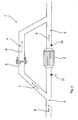
- Fig.1 is an example of an exhaust system 1 of an internal combustion engine, not shown in detail, for example, a diesel engine, shown, which has an exhaust pipe 2, which goes off from the internal combustion engine, not shown, and in the here example sigiglic example, a A bgastherapies worn 3, for example, an SCR Catalyst, is arranged.
- a diesel engine shown, which has an exhaust pipe 2, which goes off from the internal combustion engine, not shown, and in the here example sigiglic example, a A bgastherapies worn 3, for example, an SCR Catalyst, is arranged.
- the exhaust gas back pressure upstream of the exhaust gas purification device 3 is substantially increased, which also means an increased pressure on the rupture disk device 5 in the branch line 4 at the same time.
- the rupture disk device 5 bursts, thereby releasing the exhaust gas flow via the branch pipe 4, as shown in FIG Fig. 1 schematically and exemplified by the dashed arrow 8 is shown. D uring this bypass operation ensures that it can come to no disturbance ung the internal combustion engine or to stalling of the internal combustion engine.
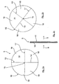
- FIG. 2a to 2c is now shown in a game-like first embodiment of a Berstusionnei device 5 according to the invention.
- This Ber stusionn Anlagen 5 is here by two in the flow direction 9 9 arranged one behind the other and in a planar contact aneinand he applied rupture disc n 10, 11 formed, each of which, in particular from the F ig. 2a and 2b can be seen, a defined predetermined breaking point pattern 12, 13 may have.
- the Sollbruc hstellmuster 12,13 can in principle be formed from the same gr as in the Fig. 2a and 2b is shown, or al ternativ but also be designed differently.
- the individual Sollbruc hstellen 14 can either by the bursting disc wall not penetrating Ker ben or alternatively by the bursting disc wall penetrating perforations g e be formed.
- the formation of the predetermined breaking points 14 of a rupture disk 10, 11 with both notches and perforations is basically always possible, of course.
- the perforations of two Anlie gender rupture discs 10, 11 are preferably rotated against each other or offset (see Fig. 2a and 2b ) that the perforations of a rupture disk 10 are each covered by a wall portion of the other rupture disk 11.
- the gas-tightness of the rupture disk device 5 is ensured.
- this is not necessary in the case of predetermined breaking points formed only by non-penetrating notches a.
- both rupture disks 10, 11 each a plurality of spaced apart and from a Middle rupture disk region 15, starting from radially outward to the rupture disk edge 16 toward Sollbr uchstellen 14, each forming a predetermined breaking line 17 from.
- These predetermined breaking lines are lines in the circumferential direction of the rupture disks 10, 11 each, for example, gl Eichich, voneinand he spaced, so that each rupture between two predetermined breaking line 17 rupture disk areas form when a Berst réelle-Sc hwellwerts displaceable or pivotable Berstusionnwandsegment 18.
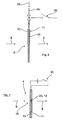
- FIG. 3 is a schematic front and rear view of the rupture disc device 5 shown, which is a central heating means 19 formed by an elec tric rupture aid, here exemplified centrally or mitt ig, assigned by means of the associated e Berstusionnwand Scheme in the activated state of the electrical chen Heating element 19 can be heated and in particular thermally destroyed.
- a central heating means 19 formed by an elec tric rupture aid here exemplified centrally or mitt ig, assigned by means of the associated e Berstusionnwand Scheme in the activated state of the electrical chen Heating element 19 can be heated and in particular thermally destroyed.
- the electric heating element 19 is here mi t coupled with a control device 20 shown only by way of example, the electronic heating element 19 preferably then controls, if, for example by means of a sensor arrangement of upstream or downstream of the Abgastherapieseinricht 3 arranged en sensor en 21, 22 detected is that the exhaust gas is roman 8 release via the branch line 4.
- the differential pressure can be measured.
- only one sensor may be provided upstream or downstream of the exhaust gas purification device 3.
- At least one of the bursting discs 10, 11 is optionally not provided with predetermined breaking points 14, because in the example shown here the Fig. 3
- the electric heating element 19 as a rupture aid, there is an additional redundancy which ensures the safe operation of the rupture disk device 5 in the respective desired operating situations.
- FIG. 3 shows a side view of a rupture disk device 5 Fig. 4 , in which the central or central Berstusionnbe rich deten a blasting element 23 with an explosive charge, which destroys the zugeor dneten Berstusionnwand Scheme in the activated state by igniting the explosive charge.
- the rupture aid is merely shown on one side of the rupture disc device 5 in the form of a pielish and schematically, this, of course, can also be arranged on the other side, that is to say in the present example of the FIG. 3 and 4, upstream of the rupture disk device 5 may be arranged.
- a mutual arrangement is also possible, as is an arrangement of the bursting aids at different locations of the respective rupture disk 10, 11.
- a supply line 25 may be provided by means of a fluid 26, in particular compressed air or What ser, at defined times and in a defined amount such between two benac hbarte and preferably substantially fläc hig abutting rupture discs 10, 11 a brought can n, that between the two rupture discs 10, 11 a the pert disruption of the same causing pressure is built up.
- the Akti vation is again controlled by means of a control device 20th
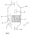
- the at least one exhaust gas cleaning device 3, for example an SCR catalytic converter, are arranged or integrated together with a rupture disk device 5 in a common housing 24.
- the a housing-side branch channel 4 occlusive Bursting disk device 5 and the exhaust gas cleaning device 3 are in this case arranged fluidically parallel, so that when intact rupture disk device 5, the exhaust gas flows alone through the exhaust gas purification device 3.
- a defined high pressure Berst bursts Bers tusionn responded 5 in the z uvor described manner, so that at least a partial flow 7 then also through the branch channel 4 can flow (Abgasström ung 8).
- the Berstschei ben driven 3 is here only by way of example laterally next to the exhaust gas purification device 3.
- the Abgastherapieseinrichtu ng also centrally in Ge housing 24 be supported and circumferentially v surrounded by a corresponding d designed rupture disk device 5.
- the bursting disk device 5 is preferably designed here as described in detail above, namely by at least two rupture disks 10, 11 arranged behind one another in the flow direction 9, in particular in a two-dimensional abutment connection, this can in the case of FIG.
- the housing integrated solution shown by way of example is of course expressly also provided by a conventional rupture disk or rupture disk, as described, for example, in US Pat DE 102 06 805 A1 besch rubbed, and thus be formed by any suitable bursting device.
Landscapes
- Engineering & Computer Science (AREA)
- Chemical & Material Sciences (AREA)
- Combustion & Propulsion (AREA)
- Mechanical Engineering (AREA)
- General Engineering & Computer Science (AREA)
- Exhaust Gas After Treatment (AREA)
- Exhaust Silencers (AREA)
Applications Claiming Priority (1)
| Application Number | Priority Date | Filing Date | Title |
|---|---|---|---|
| DE102014009262.3A DE102014009262A1 (de) | 2014-06-25 | 2014-06-25 | Abgasanlage für Brennkraftmaschinen |
Publications (3)
| Publication Number | Publication Date |
|---|---|
| EP2960450A2 true EP2960450A2 (fr) | 2015-12-30 |
| EP2960450A3 EP2960450A3 (fr) | 2016-01-13 |
| EP2960450B1 EP2960450B1 (fr) | 2018-03-14 |
Family
ID=52394888
Family Applications (1)
| Application Number | Title | Priority Date | Filing Date |
|---|---|---|---|
| EP15000201.2A Active EP2960450B1 (fr) | 2014-06-25 | 2015-01-23 | Système d'échappement pour moteurs à combustion interne |
Country Status (5)
| Country | Link |
|---|---|
| EP (1) | EP2960450B1 (fr) |
| KR (1) | KR102499443B1 (fr) |
| CN (1) | CN105317516B (fr) |
| DE (1) | DE102014009262A1 (fr) |
| DK (1) | DK2960450T3 (fr) |
Cited By (1)
| Publication number | Priority date | Publication date | Assignee | Title |
|---|---|---|---|---|
| WO2019042718A1 (fr) * | 2017-09-01 | 2019-03-07 | Thyssenkrupp Bilstein Gmbh | Dispositif de filtrage et moyen de fixation comportant un tel dispositif de filtrage |
Families Citing this family (2)
| Publication number | Priority date | Publication date | Assignee | Title |
|---|---|---|---|---|
| CA3070278C (fr) | 2018-03-13 | 2023-06-20 | Jiddu, Inc. | Appareil base sur l'ido permettant d'evaluer la qualite de produits alimentaires |
| CN109779731B (zh) * | 2019-02-28 | 2020-03-24 | 太平洋海洋工程(舟山)有限公司 | 一种用于双燃料发动机的废气排放系统 |
Citations (1)
| Publication number | Priority date | Publication date | Assignee | Title |
|---|---|---|---|---|
| DE10206805A1 (de) | 2002-02-19 | 2003-08-28 | Bosch Gmbh Robert | Russfilter und Verfahren zur Reinigung von Abgasen |
Family Cites Families (10)
| Publication number | Priority date | Publication date | Assignee | Title |
|---|---|---|---|---|
| US4479587A (en) * | 1983-09-06 | 1984-10-30 | Bs&B Safety Systems, Inc. | Two-way rupturable pressure relief apparatus |
| US4838447A (en) * | 1987-06-29 | 1989-06-13 | Bs&B Safety Systems, Inc. | Pressure relief device with conical reverse buckling disc |
| EP0638709A1 (fr) * | 1993-08-06 | 1995-02-15 | Bayerische Motoren Werke Aktiengesellschaft | Dispositif d'échappement pour moteurs à combustion interne |
| US5377716A (en) * | 1993-08-16 | 1995-01-03 | Bs&B Safety Systems, Inc. | Pressure surge resistant rupture disk assembly |
| US5368180A (en) * | 1993-10-12 | 1994-11-29 | Bs&B Safety Systems, Inc. | Perforated rupture disk assembly |
| DE10000921B4 (de) * | 2000-01-12 | 2012-03-01 | Volkswagen Ag | Partikelfiltersystem, insbesondere für Dieselmotoren |
| WO2004002764A1 (fr) * | 2002-06-27 | 2004-01-08 | Luk Fahrzeugh-Hydraulik Gmbh & Co. Kg | Installation de climatisation dotee d'un equipement a plaque de rupture |
| DE102007013500A1 (de) * | 2007-03-21 | 2008-09-25 | Bayerische Motoren Werke Aktiengesellschaft | Abgasstrang für einen Verbrennungsmotor |
| WO2013063137A1 (fr) * | 2011-10-26 | 2013-05-02 | Boshart Automotive Testing Service, Inc. | Dispositif de sécurité surtempérature/pression pour filtres à particules de diesel |
| CN103574114A (zh) * | 2013-10-29 | 2014-02-12 | 大连理工大学 | 主动与被动结合的双功能超压泄放装置及超压泄放方法 |
-
2014
- 2014-06-25 DE DE102014009262.3A patent/DE102014009262A1/de active Pending
-
2015
- 2015-01-23 DK DK15000201.2T patent/DK2960450T3/da active
- 2015-01-23 EP EP15000201.2A patent/EP2960450B1/fr active Active
- 2015-04-24 KR KR1020150057860A patent/KR102499443B1/ko active Active
- 2015-06-25 CN CN201510355972.7A patent/CN105317516B/zh active Active
Patent Citations (1)
| Publication number | Priority date | Publication date | Assignee | Title |
|---|---|---|---|---|
| DE10206805A1 (de) | 2002-02-19 | 2003-08-28 | Bosch Gmbh Robert | Russfilter und Verfahren zur Reinigung von Abgasen |
Cited By (2)
| Publication number | Priority date | Publication date | Assignee | Title |
|---|---|---|---|---|
| WO2019042718A1 (fr) * | 2017-09-01 | 2019-03-07 | Thyssenkrupp Bilstein Gmbh | Dispositif de filtrage et moyen de fixation comportant un tel dispositif de filtrage |
| US11471809B2 (en) | 2017-09-01 | 2022-10-18 | Thyssenkrupp Bilstein Gmbh | Filter device and fixing means comprising a filter device of this type |
Also Published As
| Publication number | Publication date |
|---|---|
| KR102499443B1 (ko) | 2023-02-15 |
| CN105317516B (zh) | 2019-11-08 |
| DK2960450T3 (da) | 2018-06-14 |
| EP2960450B1 (fr) | 2018-03-14 |
| KR20160000831A (ko) | 2016-01-05 |
| CN105317516A (zh) | 2016-02-10 |
| DE102014009262A1 (de) | 2015-12-31 |
| EP2960450A3 (fr) | 2016-01-13 |
Similar Documents
| Publication | Publication Date | Title |
|---|---|---|
| DE102012218740A1 (de) | Anordnung zum Mischen einer Flüssigkeit in einer Gasströmung | |
| EP3017176B1 (fr) | Procédé de régénération d'un élément filtrant bouché d'un système d'échappement et système d'échappement | |
| EP3346103B1 (fr) | Installation de gaz d'échappement | |
| EP2960450A2 (fr) | Système d'échappement pour moteurs à combustion interne | |
| DE112007000298B4 (de) | Auspuffelement für Anlage zum Ausströmen von Gasen | |
| EP2166204A1 (fr) | Bougie de préchauffage à flamme | |
| DE102009020625A1 (de) | Verbrennungskraftmaschine | |
| EP2960451B1 (fr) | Système d'échappement pour moteurs à combustion interne | |
| DE102017218302B4 (de) | Ventileinrichtung zum Steuern eines Abgasstroms | |
| EP2064422B1 (fr) | Dispositif de traitement des gaz d'echappement et son utilisation | |
| DE102011081569A1 (de) | Vorrichtung zur Aufteilung eines Gesamtluftstroms zum Betrieb eines Abgasbrenners mit einem inneren und einem äußeren Brennraum | |
| EP2960452B1 (fr) | Système d'échappement pour moteurs à combustion interne | |
| DE10120973B4 (de) | Abgasreinigungsanlage mit Partikelfiltermitteln und Regenerationsverfahren für Partikelfiltermittel | |
| DE102010025699A1 (de) | Brennkraftmaschine mit Abgasnachbehandlung und Abgasrückführung | |
| EP1715162B1 (fr) | Système d'évacuation des gaz d'échappement d'un moteur à combustion interne et clapet d'obturation pour un système d'évacuation des gaz d'échappement | |
| DE10000921A1 (de) | Partikelfiltersystem, insbesondere für Dieselmotoren | |
| DE102018120195A1 (de) | Vorrichtung und Verfahren zur Abgasnachbehandlung eines Verbrennungsmotors | |
| DE102017218838A1 (de) | Brennkraftmaschine mit einer Abgasanlage | |
| DE102009029259B4 (de) | Filteranordnung einer Abgasnachbehandlungseinrichtung | |
| DE10210950A1 (de) | Rußfilter mit Umkehr der Abgasströmungsrichtung | |
| DE102004001571B4 (de) | Vorrichtung zur Regeneration eines Partikelfilters | |
| DE102010008273B4 (de) | Partikelfilteranordnung | |
| DE102019203153A1 (de) | Antriebseinrichtung für ein Kraftfahrzeug sowie Verfahren zum Betreiben einer Antriebseinrichtung | |
| DE102018106092A1 (de) | Abgasnachbehandlung für einen verbrennungsmotor | |
| DE102014209063A1 (de) | Abgaspartikelfilter und Abgaspartikel-Filtersystem für einen Verbrennungsmotor sowie Fahrzeugantrieb nebst entsprechend ausgestattetem Fahrzeug |
Legal Events
| Date | Code | Title | Description |
|---|---|---|---|
| PUAL | Search report despatched |
Free format text: ORIGINAL CODE: 0009013 |
|
| PUAI | Public reference made under article 153(3) epc to a published international application that has entered the european phase |
Free format text: ORIGINAL CODE: 0009012 |
|
| AK | Designated contracting states |
Kind code of ref document: A2 Designated state(s): AL AT BE BG CH CY CZ DE DK EE ES FI FR GB GR HR HU IE IS IT LI LT LU LV MC MK MT NL NO PL PT RO RS SE SI SK SM TR |
|
| AX | Request for extension of the european patent |
Extension state: BA ME |
|
| AK | Designated contracting states |
Kind code of ref document: A3 Designated state(s): AL AT BE BG CH CY CZ DE DK EE ES FI FR GB GR HR HU IE IS IT LI LT LU LV MC MK MT NL NO PL PT RO RS SE SI SK SM TR |
|
| AX | Request for extension of the european patent |
Extension state: BA ME |
|
| RIC1 | Information provided on ipc code assigned before grant |
Ipc: B01D 46/00 20060101ALI20151204BHEP Ipc: F01N 3/031 20060101AFI20151204BHEP |
|
| 17P | Request for examination filed |
Effective date: 20160712 |
|
| STAA | Information on the status of an ep patent application or granted ep patent |
Free format text: STATUS: EXAMINATION IS IN PROGRESS |
|
| 17Q | First examination report despatched |
Effective date: 20170529 |
|
| GRAP | Despatch of communication of intention to grant a patent |
Free format text: ORIGINAL CODE: EPIDOSNIGR1 |
|
| STAA | Information on the status of an ep patent application or granted ep patent |
Free format text: STATUS: GRANT OF PATENT IS INTENDED |
|
| INTG | Intention to grant announced |
Effective date: 20170818 |
|
| GRAS | Grant fee paid |
Free format text: ORIGINAL CODE: EPIDOSNIGR3 |
|
| GRAA | (expected) grant |
Free format text: ORIGINAL CODE: 0009210 |
|
| STAA | Information on the status of an ep patent application or granted ep patent |
Free format text: STATUS: THE PATENT HAS BEEN GRANTED |
|
| AK | Designated contracting states |
Kind code of ref document: B1 Designated state(s): AL AT BE BG CH CY CZ DE DK EE ES FI FR GB GR HR HU IE IS IT LI LT LU LV MC MK MT NL NO PL PT RO RS SE SI SK SM TR |
|
| REG | Reference to a national code |
Ref country code: GB Ref legal event code: FG4D Free format text: NOT ENGLISH |
|
| REG | Reference to a national code |
Ref country code: CH Ref legal event code: EP Ref country code: AT Ref legal event code: REF Ref document number: 979097 Country of ref document: AT Kind code of ref document: T Effective date: 20180315 |
|
| REG | Reference to a national code |
Ref country code: IE Ref legal event code: FG4D Free format text: LANGUAGE OF EP DOCUMENT: GERMAN |
|
| REG | Reference to a national code |
Ref country code: DE Ref legal event code: R096 Ref document number: 502015003327 Country of ref document: DE |
|
| REG | Reference to a national code |
Ref country code: NL Ref legal event code: FP |
|
| REG | Reference to a national code |
Ref country code: DK Ref legal event code: T3 Effective date: 20180607 |
|
| REG | Reference to a national code |
Ref country code: SE Ref legal event code: TRGR |
|
| REG | Reference to a national code |
Ref country code: LT Ref legal event code: MG4D |
|
| PG25 | Lapsed in a contracting state [announced via postgrant information from national office to epo] |
Ref country code: NO Free format text: LAPSE BECAUSE OF FAILURE TO SUBMIT A TRANSLATION OF THE DESCRIPTION OR TO PAY THE FEE WITHIN THE PRESCRIBED TIME-LIMIT Effective date: 20180614 Ref country code: LT Free format text: LAPSE BECAUSE OF FAILURE TO SUBMIT A TRANSLATION OF THE DESCRIPTION OR TO PAY THE FEE WITHIN THE PRESCRIBED TIME-LIMIT Effective date: 20180314 Ref country code: HR Free format text: LAPSE BECAUSE OF FAILURE TO SUBMIT A TRANSLATION OF THE DESCRIPTION OR TO PAY THE FEE WITHIN THE PRESCRIBED TIME-LIMIT Effective date: 20180314 Ref country code: CY Free format text: LAPSE BECAUSE OF FAILURE TO SUBMIT A TRANSLATION OF THE DESCRIPTION OR TO PAY THE FEE WITHIN THE PRESCRIBED TIME-LIMIT Effective date: 20180314 Ref country code: FI Free format text: LAPSE BECAUSE OF FAILURE TO SUBMIT A TRANSLATION OF THE DESCRIPTION OR TO PAY THE FEE WITHIN THE PRESCRIBED TIME-LIMIT Effective date: 20180314 |
|
| PG25 | Lapsed in a contracting state [announced via postgrant information from national office to epo] |
Ref country code: GR Free format text: LAPSE BECAUSE OF FAILURE TO SUBMIT A TRANSLATION OF THE DESCRIPTION OR TO PAY THE FEE WITHIN THE PRESCRIBED TIME-LIMIT Effective date: 20180615 Ref country code: LV Free format text: LAPSE BECAUSE OF FAILURE TO SUBMIT A TRANSLATION OF THE DESCRIPTION OR TO PAY THE FEE WITHIN THE PRESCRIBED TIME-LIMIT Effective date: 20180314 Ref country code: RS Free format text: LAPSE BECAUSE OF FAILURE TO SUBMIT A TRANSLATION OF THE DESCRIPTION OR TO PAY THE FEE WITHIN THE PRESCRIBED TIME-LIMIT Effective date: 20180314 Ref country code: BG Free format text: LAPSE BECAUSE OF FAILURE TO SUBMIT A TRANSLATION OF THE DESCRIPTION OR TO PAY THE FEE WITHIN THE PRESCRIBED TIME-LIMIT Effective date: 20180614 |
|
| PG25 | Lapsed in a contracting state [announced via postgrant information from national office to epo] |
Ref country code: MT Free format text: LAPSE BECAUSE OF FAILURE TO SUBMIT A TRANSLATION OF THE DESCRIPTION OR TO PAY THE FEE WITHIN THE PRESCRIBED TIME-LIMIT Effective date: 20180314 |
|
| PG25 | Lapsed in a contracting state [announced via postgrant information from national office to epo] |
Ref country code: EE Free format text: LAPSE BECAUSE OF FAILURE TO SUBMIT A TRANSLATION OF THE DESCRIPTION OR TO PAY THE FEE WITHIN THE PRESCRIBED TIME-LIMIT Effective date: 20180314 Ref country code: PL Free format text: LAPSE BECAUSE OF FAILURE TO SUBMIT A TRANSLATION OF THE DESCRIPTION OR TO PAY THE FEE WITHIN THE PRESCRIBED TIME-LIMIT Effective date: 20180314 Ref country code: AL Free format text: LAPSE BECAUSE OF FAILURE TO SUBMIT A TRANSLATION OF THE DESCRIPTION OR TO PAY THE FEE WITHIN THE PRESCRIBED TIME-LIMIT Effective date: 20180314 Ref country code: ES Free format text: LAPSE BECAUSE OF FAILURE TO SUBMIT A TRANSLATION OF THE DESCRIPTION OR TO PAY THE FEE WITHIN THE PRESCRIBED TIME-LIMIT Effective date: 20180314 Ref country code: RO Free format text: LAPSE BECAUSE OF FAILURE TO SUBMIT A TRANSLATION OF THE DESCRIPTION OR TO PAY THE FEE WITHIN THE PRESCRIBED TIME-LIMIT Effective date: 20180314 |
|
| PG25 | Lapsed in a contracting state [announced via postgrant information from national office to epo] |
Ref country code: CZ Free format text: LAPSE BECAUSE OF FAILURE TO SUBMIT A TRANSLATION OF THE DESCRIPTION OR TO PAY THE FEE WITHIN THE PRESCRIBED TIME-LIMIT Effective date: 20180314 Ref country code: SM Free format text: LAPSE BECAUSE OF FAILURE TO SUBMIT A TRANSLATION OF THE DESCRIPTION OR TO PAY THE FEE WITHIN THE PRESCRIBED TIME-LIMIT Effective date: 20180314 Ref country code: SK Free format text: LAPSE BECAUSE OF FAILURE TO SUBMIT A TRANSLATION OF THE DESCRIPTION OR TO PAY THE FEE WITHIN THE PRESCRIBED TIME-LIMIT Effective date: 20180314 |
|
| REG | Reference to a national code |
Ref country code: DE Ref legal event code: R097 Ref document number: 502015003327 Country of ref document: DE |
|
| PG25 | Lapsed in a contracting state [announced via postgrant information from national office to epo] |
Ref country code: PT Free format text: LAPSE BECAUSE OF FAILURE TO SUBMIT A TRANSLATION OF THE DESCRIPTION OR TO PAY THE FEE WITHIN THE PRESCRIBED TIME-LIMIT Effective date: 20180716 |
|
| PLBE | No opposition filed within time limit |
Free format text: ORIGINAL CODE: 0009261 |
|
| STAA | Information on the status of an ep patent application or granted ep patent |
Free format text: STATUS: NO OPPOSITION FILED WITHIN TIME LIMIT |
|
| 26N | No opposition filed |
Effective date: 20181217 |
|
| PG25 | Lapsed in a contracting state [announced via postgrant information from national office to epo] |
Ref country code: SI Free format text: LAPSE BECAUSE OF FAILURE TO SUBMIT A TRANSLATION OF THE DESCRIPTION OR TO PAY THE FEE WITHIN THE PRESCRIBED TIME-LIMIT Effective date: 20180314 |
|
| PG25 | Lapsed in a contracting state [announced via postgrant information from national office to epo] |
Ref country code: MC Free format text: LAPSE BECAUSE OF FAILURE TO SUBMIT A TRANSLATION OF THE DESCRIPTION OR TO PAY THE FEE WITHIN THE PRESCRIBED TIME-LIMIT Effective date: 20180314 |
|
| REG | Reference to a national code |
Ref country code: CH Ref legal event code: PL |
|
| GBPC | Gb: european patent ceased through non-payment of renewal fee |
Effective date: 20190123 |
|
| REG | Reference to a national code |
Ref country code: DE Ref legal event code: R081 Ref document number: 502015003327 Country of ref document: DE Owner name: MAN TRUCK & BUS SE, DE Free format text: FORMER OWNER: MAN TRUCK & BUS AG, 80995 MUENCHEN, DE |
|
| PG25 | Lapsed in a contracting state [announced via postgrant information from national office to epo] |
Ref country code: LU Free format text: LAPSE BECAUSE OF NON-PAYMENT OF DUE FEES Effective date: 20190123 |
|
| REG | Reference to a national code |
Ref country code: BE Ref legal event code: MM Effective date: 20190131 |
|
| REG | Reference to a national code |
Ref country code: IE Ref legal event code: MM4A |
|
| PG25 | Lapsed in a contracting state [announced via postgrant information from national office to epo] |
Ref country code: BE Free format text: LAPSE BECAUSE OF NON-PAYMENT OF DUE FEES Effective date: 20190131 |
|
| PG25 | Lapsed in a contracting state [announced via postgrant information from national office to epo] |
Ref country code: CH Free format text: LAPSE BECAUSE OF NON-PAYMENT OF DUE FEES Effective date: 20190131 Ref country code: GB Free format text: LAPSE BECAUSE OF NON-PAYMENT OF DUE FEES Effective date: 20190123 Ref country code: LI Free format text: LAPSE BECAUSE OF NON-PAYMENT OF DUE FEES Effective date: 20190131 |
|
| PG25 | Lapsed in a contracting state [announced via postgrant information from national office to epo] |
Ref country code: IE Free format text: LAPSE BECAUSE OF NON-PAYMENT OF DUE FEES Effective date: 20190123 |
|
| PG25 | Lapsed in a contracting state [announced via postgrant information from national office to epo] |
Ref country code: TR Free format text: LAPSE BECAUSE OF FAILURE TO SUBMIT A TRANSLATION OF THE DESCRIPTION OR TO PAY THE FEE WITHIN THE PRESCRIBED TIME-LIMIT Effective date: 20180314 |
|
| REG | Reference to a national code |
Ref country code: AT Ref legal event code: MM01 Ref document number: 979097 Country of ref document: AT Kind code of ref document: T Effective date: 20200123 |
|
| PG25 | Lapsed in a contracting state [announced via postgrant information from national office to epo] |
Ref country code: AT Free format text: LAPSE BECAUSE OF NON-PAYMENT OF DUE FEES Effective date: 20200123 |
|
| PG25 | Lapsed in a contracting state [announced via postgrant information from national office to epo] |
Ref country code: IS Free format text: LAPSE BECAUSE OF FAILURE TO SUBMIT A TRANSLATION OF THE DESCRIPTION OR TO PAY THE FEE WITHIN THE PRESCRIBED TIME-LIMIT Effective date: 20180714 |
|
| PG25 | Lapsed in a contracting state [announced via postgrant information from national office to epo] |
Ref country code: HU Free format text: LAPSE BECAUSE OF FAILURE TO SUBMIT A TRANSLATION OF THE DESCRIPTION OR TO PAY THE FEE WITHIN THE PRESCRIBED TIME-LIMIT; INVALID AB INITIO Effective date: 20150123 |
|
| PG25 | Lapsed in a contracting state [announced via postgrant information from national office to epo] |
Ref country code: MK Free format text: LAPSE BECAUSE OF FAILURE TO SUBMIT A TRANSLATION OF THE DESCRIPTION OR TO PAY THE FEE WITHIN THE PRESCRIBED TIME-LIMIT Effective date: 20180314 |
|
| PGFP | Annual fee paid to national office [announced via postgrant information from national office to epo] |
Ref country code: NL Payment date: 20260122 Year of fee payment: 12 |
|
| PGFP | Annual fee paid to national office [announced via postgrant information from national office to epo] |
Ref country code: SE Payment date: 20260126 Year of fee payment: 12 |
|
| PGFP | Annual fee paid to national office [announced via postgrant information from national office to epo] |
Ref country code: DE Payment date: 20260127 Year of fee payment: 12 Ref country code: DK Payment date: 20260123 Year of fee payment: 12 |
|
| PGFP | Annual fee paid to national office [announced via postgrant information from national office to epo] |
Ref country code: IT Payment date: 20260123 Year of fee payment: 12 |
|
| PGFP | Annual fee paid to national office [announced via postgrant information from national office to epo] |
Ref country code: FR Payment date: 20260127 Year of fee payment: 12 |