EP2960452B1 - Abgasanlage für Brennkraftmaschinen - Google Patents
Abgasanlage für Brennkraftmaschinen Download PDFInfo
- Publication number
- EP2960452B1 EP2960452B1 EP15000204.6A EP15000204A EP2960452B1 EP 2960452 B1 EP2960452 B1 EP 2960452B1 EP 15000204 A EP15000204 A EP 15000204A EP 2960452 B1 EP2960452 B1 EP 2960452B1
- Authority
- EP
- European Patent Office
- Prior art keywords
- exhaust gas
- bursting
- gas purification
- bursting disc
- exhaust
- Prior art date
- Legal status (The legal status is an assumption and is not a legal conclusion. Google has not performed a legal analysis and makes no representation as to the accuracy of the status listed.)
- Active
Links
Images

Classifications
-
- F—MECHANICAL ENGINEERING; LIGHTING; HEATING; WEAPONS; BLASTING
- F01—MACHINES OR ENGINES IN GENERAL; ENGINE PLANTS IN GENERAL; STEAM ENGINES
- F01N—GAS-FLOW SILENCERS OR EXHAUST APPARATUS FOR MACHINES OR ENGINES IN GENERAL; GAS-FLOW SILENCERS OR EXHAUST APPARATUS FOR INTERNAL-COMBUSTION ENGINES
- F01N3/00—Exhaust or silencing apparatus having means for purifying, rendering innocuous, or otherwise treating exhaust
- F01N3/02—Exhaust or silencing apparatus having means for purifying, rendering innocuous, or otherwise treating exhaust for cooling, or for removing solid constituents of, exhaust
- F01N3/021—Exhaust or silencing apparatus having means for purifying, rendering innocuous, or otherwise treating exhaust for cooling, or for removing solid constituents of, exhaust by means of filters
- F01N3/031—Exhaust or silencing apparatus having means for purifying, rendering innocuous, or otherwise treating exhaust for cooling, or for removing solid constituents of, exhaust by means of filters having means for by-passing filters, e.g. when clogged or during cold engine start
-
- F—MECHANICAL ENGINEERING; LIGHTING; HEATING; WEAPONS; BLASTING
- F01—MACHINES OR ENGINES IN GENERAL; ENGINE PLANTS IN GENERAL; STEAM ENGINES
- F01N—GAS-FLOW SILENCERS OR EXHAUST APPARATUS FOR MACHINES OR ENGINES IN GENERAL; GAS-FLOW SILENCERS OR EXHAUST APPARATUS FOR INTERNAL-COMBUSTION ENGINES
- F01N2260/00—Exhaust treating devices having provisions not otherwise provided for
- F01N2260/06—Exhaust treating devices having provisions not otherwise provided for for improving exhaust evacuation or circulation, or reducing back-pressure
-
- F—MECHANICAL ENGINEERING; LIGHTING; HEATING; WEAPONS; BLASTING
- F01—MACHINES OR ENGINES IN GENERAL; ENGINE PLANTS IN GENERAL; STEAM ENGINES
- F01N—GAS-FLOW SILENCERS OR EXHAUST APPARATUS FOR MACHINES OR ENGINES IN GENERAL; GAS-FLOW SILENCERS OR EXHAUST APPARATUS FOR INTERNAL-COMBUSTION ENGINES
- F01N2410/00—By-passing, at least partially, exhaust from inlet to outlet of apparatus, to atmosphere or to other device
-
- F—MECHANICAL ENGINEERING; LIGHTING; HEATING; WEAPONS; BLASTING
- F01—MACHINES OR ENGINES IN GENERAL; ENGINE PLANTS IN GENERAL; STEAM ENGINES
- F01N—GAS-FLOW SILENCERS OR EXHAUST APPARATUS FOR MACHINES OR ENGINES IN GENERAL; GAS-FLOW SILENCERS OR EXHAUST APPARATUS FOR INTERNAL-COMBUSTION ENGINES
- F01N2410/00—By-passing, at least partially, exhaust from inlet to outlet of apparatus, to atmosphere or to other device
- F01N2410/08—By-passing, at least partially, exhaust from inlet to outlet of apparatus, to atmosphere or to other device in case of clogging, e.g. of particle filter
-
- F—MECHANICAL ENGINEERING; LIGHTING; HEATING; WEAPONS; BLASTING
- F01—MACHINES OR ENGINES IN GENERAL; ENGINE PLANTS IN GENERAL; STEAM ENGINES
- F01N—GAS-FLOW SILENCERS OR EXHAUST APPARATUS FOR MACHINES OR ENGINES IN GENERAL; GAS-FLOW SILENCERS OR EXHAUST APPARATUS FOR INTERNAL-COMBUSTION ENGINES
- F01N2410/00—By-passing, at least partially, exhaust from inlet to outlet of apparatus, to atmosphere or to other device
- F01N2410/14—By-passing, at least partially, exhaust from inlet to outlet of apparatus, to atmosphere or to other device in case of excessive pressure, e.g. using a safety valve
-
- F—MECHANICAL ENGINEERING; LIGHTING; HEATING; WEAPONS; BLASTING
- F01—MACHINES OR ENGINES IN GENERAL; ENGINE PLANTS IN GENERAL; STEAM ENGINES
- F01N—GAS-FLOW SILENCERS OR EXHAUST APPARATUS FOR MACHINES OR ENGINES IN GENERAL; GAS-FLOW SILENCERS OR EXHAUST APPARATUS FOR INTERNAL-COMBUSTION ENGINES
- F01N2590/00—Exhaust or silencing apparatus adapted to particular use, e.g. for military applications, airplanes, submarines
- F01N2590/02—Exhaust or silencing apparatus adapted to particular use, e.g. for military applications, airplanes, submarines for marine vessels or naval applications
-
- F—MECHANICAL ENGINEERING; LIGHTING; HEATING; WEAPONS; BLASTING
- F01—MACHINES OR ENGINES IN GENERAL; ENGINE PLANTS IN GENERAL; STEAM ENGINES
- F01N—GAS-FLOW SILENCERS OR EXHAUST APPARATUS FOR MACHINES OR ENGINES IN GENERAL; GAS-FLOW SILENCERS OR EXHAUST APPARATUS FOR INTERNAL-COMBUSTION ENGINES
- F01N2590/00—Exhaust or silencing apparatus adapted to particular use, e.g. for military applications, airplanes, submarines
- F01N2590/08—Exhaust or silencing apparatus adapted to particular use, e.g. for military applications, airplanes, submarines for heavy duty applications, e.g. trucks, buses, tractors, locomotives
-
- Y—GENERAL TAGGING OF NEW TECHNOLOGICAL DEVELOPMENTS; GENERAL TAGGING OF CROSS-SECTIONAL TECHNOLOGIES SPANNING OVER SEVERAL SECTIONS OF THE IPC; TECHNICAL SUBJECTS COVERED BY FORMER USPC CROSS-REFERENCE ART COLLECTIONS [XRACs] AND DIGESTS
- Y02—TECHNOLOGIES OR APPLICATIONS FOR MITIGATION OR ADAPTATION AGAINST CLIMATE CHANGE
- Y02T—CLIMATE CHANGE MITIGATION TECHNOLOGIES RELATED TO TRANSPORTATION
- Y02T10/00—Road transport of goods or passengers
- Y02T10/10—Internal combustion engine [ICE] based vehicles
- Y02T10/12—Improving ICE efficiencies
Definitions
- the invention relates to an exhaust system for internal combustion engines according to the preamble of claim 1 or a vehicle or watercraft, in particular a ship, according to claim 13.
- exhaust gas purification elements In order to reduce the resulting in the combustion of fuels in internal combustion engines, such as diesel engines pollutants, the use of Abgastherapies- or exhaust aftertreatment devices in the form of exhaust gas purification elements is well known.
- Such exhaust gas purification elements for aftertreatment of the exhaust gas may be, for example, particulate filters, SCR catalysts, etc.
- shut-off devices in the form of exhaust valves or exhaust valves are used.
- an air purge is usually provided at the shaft passages of the exhaust valve in order to avoid exhaust gas leakage into the environment. This leads to a relatively high expenditure on equipment and high investment and operating costs, since permanent compressed air must be made available.
- soot filter for purifying exhaust gases of an internal combustion engine of a motor vehicle with means for reducing an exhaust back pressure prevailing in the soot filter, wherein the means for reducing the exhaust back pressure at least one predetermined breaking point in a filter body of the filter and / or in a bypass line of the filter should have.
- the predetermined breaking point in the bypass line is designed as a bursting plate. This should be avoided with a clogged soot filter dying or damage to the engine.
- the bursting plate arranged in the bypass line can be mechanically ruptured in dependence on a measured exhaust gas back pressure, should, however, be disrupted mainly without the need for additional measures.
- a particulate filter system with an exhaust manifold, in which a particulate filter is arranged.
- a bypass channel is integrated, which is provided in the flow direction at the end thereof with a bursting plate and this completes.
- an exhaust system for internal combustion engines which has an exhaust pipe in which at least one exhaust gas purification element (for example, a particle filter, an SCR catalyst and / or a DeSOx system, etc.) is arranged. Furthermore, the exhaust gas line has at least one branch channel arranged parallel to the at least one exhaust gas purification element (for example at least one branch channel branching upstream of at least one or upstream of at least one exhaust gas purification element), in which a bursting disc device bursting at a defined bursting pressure is arranged.
- at least one exhaust gas purification element for example, a particle filter, an SCR catalyst and / or a DeSOx system, etc.
- the exhaust gas line has at least one branch channel arranged parallel to the at least one exhaust gas purification element (for example at least one branch channel branching upstream of at least one or upstream of at least one exhaust gas purification element), in which a bursting disc device bursting at a defined bursting pressure is arranged.
- the at least one exhaust gas purification element are arranged together with the rupture disk device in a common housing forming part of the exhaust pipe, the rupture disk device being fluidly parallel to the at least one Exhaust gas purification element is arranged so that it bursts at a defined bursting pressure and thus the exhaust gas flow is released through the and / or to the branch channel.
- the branch channel is not completely closed by the rupture disc associated therewith in the basic position, but forms the branch channel extending parallel to at least one main flow channel and can be flowed through by a flow of exhaust gas flow channel.
- at least one exhaust gas purification element is preferably arranged in each of the at least one main flow channel and in the branch channel, wherein the main flow channel side and branch channel side exhaust gas cleaning elements are offset locally in the branch channel in the flow direction such that the at least one branch channel side exhaust gas purification element upstream of the at least one main flow channel side exhaust gas purification element is located.
- the at least one rupture disk device is then arranged in a common wall region of the at least one main flow channel and the branch channel lying between the main flow channel side and branch channel side exhaust gas cleaning elements, the at least one rupture writing device bursting at a defined rupture pressure and the exhaust flow from the at least one main flow channel the branch channel downstream of the local at least one Emission control element releases.
- the staggered arrangement of the main flow passage side and branch passage side exhaust gas purifying devices in conjunction with the rupture disc device therebetween ensures that if the at least one upstream exhaust purification element of the main flow passage should be clogged to such an extent in the main flow channel, builds up a certain pressure threshold bursting pressure, the rupture disk device is destroyed and then the overflow of the main flow channel side exhaust stream is then allowed to bypass the branch passage, namely downstream of the branch channel side at least one exhaust gas purification element to the unimpeded flow through the exhaust pipe with the Ensure exhaust flow.
- At least one further exhaust-gas purification element may be arranged downstream of the rupture disk device in the branch-off conduit, whereby then also the further purification of the exhaust-gas flow would be ensured.
- the housing may in this case be an integral part of the exhaust pipe or else be formed by a separate component which is inserted into the exhaust pipe.
- the branch duct and at least one main flow duct having the at least one exhaust gas purification element lead into a common housing region downstream of the at least one exhaust gas purification element, specifically into a common housing region leading out of the housing for the exhaust gas. This ensures that even at a Exhaust flow via the branch channel to set the desired flow conditions in the housing, and analogous to an exhaust gas flow over the main flow channel, in which the at least one exhaust gas purification element is arranged.
- branch channel and the at least one main flow channel open downstream of their respective exhaust gas cleaning elements in a common housing area, and in particular open into a leading to a discharge from the housing common housing area. This causes a compact design.
- the wall region having at least one rupture disk device can be aligned at an angle with respect to the flow direction, at least in the area of the rupture disk device, and in particular at an angle to the upstream at least one exhaust gas cleaning element. With such an angular orientation it is ensured that a sufficient bursting force acts on the rupture disk device upstream of the at least one main flow channel-side exhaust gas purification element in the case of an exhaust gas flow.
- the rupture disk device itself can be designed in many different ways, for example, be formed by a simple, conventional rupture disk.
- the rupture disk device can be formed by at least two rupture disks arranged one behind the other in the flow direction, in particular abutting one another in a planar contact connection.
- these may, as just mentioned, in principle abut each other in a planar abutment connection.
- these can also have a defined predetermined gap distance from each other.
- a particularly reliable and functionally reliable activation of the rupture disk device is provided when the rupture disk device is assigned a controllable and activatable rupture aid by means of a control device as a function of at least one defined parameter, in particular depending on reaching or exceeding a defined predetermined threshold value.
- This rupture aid can be formed by at least one heating element, in particular at least one electric heating element, and / or by at least one explosive element and / or by a gaseous or liquid working medium, by means of which or by which the at least one rupture disk for releasing the exhaust gas flow through the and / or weakenable and / or destructible to the branch channel.
- the at least one rupture disk of the rupture disk device can thus be destroyed in a controlled manner at the exact desired time and thus the exhaust gas flow can be released via or to the branch duct at the appropriate time. This helps significantly to increase the reliability of the exhaust system with respect to the flow of exhaust gas through the branch channel.
- At least one sensor is arranged upstream and / or downstream of the at least one exhaust gas purification element in the at least one main flow channel, by means of which the at least one parameter can be detected, as a function of which the rupture aid can be activated and activated is.
- the Berst depending on one by means of several Sensors were made to measure exhaust backpressure via an exhaust gas purifier to ensure that the rupture disc is ruptured at the exact moment it is needed.
- the activation of the rupture disk can also be carried out as a function of other exhaust gas parameters, for example as a function of an exhaust gas temperature and / or a substance concentration in the exhaust gas, to name just a few further examples.
- the Best Schutting is formed by at least one electric heating element, which is arranged at a defined location of the rupture disk, in particular centrally or centrally, and which heats the associated bursting disk wall area in the activated state, in particular thermally destroyed.
- an electric heating element With such an electric heating element, a particularly reliable and reliable rupture aid is provided.
- the bursting aid can also be formed by at least one blasting element, which is arranged at a defined location of the rupture disk, in particular centrally and / or centrally, and destroys the associated bursting disk wall area in the activated state by igniting an explosive charge. Again, a very high level of functional reliability is achieved upon actuation of the rupture aid, which causes a reliable destruction of the rupture disk.
- the rupture disk may at least partially be double-walled and have a space lying between opposite wall space, wherein the free space by means of a feeder such with the gaseous or liquid working medium is chargeable that acting from the free space and thus from the inside on the bursting disk walls Bursting pressure is buildable.
- a feeder such with the gaseous or liquid working medium is chargeable that acting from the free space and thus from the inside on the bursting disk walls Bursting pressure is buildable.
- Particularly preferred here are two spaced apart and / or im Provided substantially parallel rupture discs, which have between them, the free space forming gap distance.
- the rupture disk is assigned a compressed air supply device as a rupture aid, preferably in such a way that an orifice opening of the compressed air supply device is directed substantially centrally onto the rupture disk.
- a compressed air supply device By means of such a compressed air supply device, a defined predetermined number of compressed air pulses and / or pulses, preferably in an interval or pulse-like manner, can be applied to a defined region of the rupture disk in a controlled manner.
- it is preferably a single-wall or bursting disc design.
- compressed air can of course be used in this embodiment, any other suitable gaseous or expressly liquid medium use.
- compressed air here is thus to be understood in a broad and not limited to compressed air as such meaning.
- At least one explosion pressure detection device in particular at least one pressure sensor or at least one microphone, is arranged in the exhaust tract of the internal combustion engine, by means of which an explosion and thus a sudden increase in pressure can be detected.
- the explosion pressure detection device is coupled to a control device, by means of which a bursting aid can be triggered in an explosion detection in such a way that the at least one bursting disk device is destroyed by the pressure wave before the bursting disk device is reached by means of the bursting aid.
- the destruction of the bursting disc direction can basically be as described above, that is, for example, by an electric heating element, by an explosive charge, by a compressed air pulse, etc ..
- the housing and the at least one exhaust gas cleaning element are designed so that they withstand a pressure increase of at least 300 mbar, preferably of at least 400 mbar and most preferably of at least 480 mbar. This ensures that even with a pressure increase caused by a pressure wave or an explosion in the exhaust tract no damage to the housing or of the at least one exhaust gas purification element takes place.
- the at least one bursting disk or, in the case of a plurality of bursting disks, at least one of the bursting disks, in particular at least the upstream bursting disk can have at least one defined predetermined breaking point.
- predetermined breaking points an individual adaptation and design of the rupture disk on or for the particular application is possible.
- predetermined breaking points exactly those areas can be defined and defined, at which the rupture disk should ultimately burst.
- the at least one predetermined breaking point is formed by a not penetrating the rupture disk notch.
- a rupture disk having a predetermined breaking point has a plurality of notches, which form a defined predetermined predetermined breaking point pattern. This makes it possible to rupture or burst open the rupture disc in a desired manner.
- the predetermined breaking point pattern can basically be designed in different ways. However, particularly preferred is a structure in which a plurality of spaced apart and starting from a middle rupture disk area radially outward to the rupture disk edge outwardly extending predetermined breaking points, which form a predetermined breaking point line. At least two such predetermined breaking line locations can then be spaced apart in the circumferential direction of the rupture disk such that the rupture disk regions lying between two predetermined breaking line lines form a displaceable, in particular pivotable, rupture disk wall segment. These rupture disk wall segments then regularly form rags after bursting, which can be displaced or pivoted very well and in a controlled manner for the defined release of the exhaust gas streams through or to the branch duct.
- the rupture aid can in principle also be accommodated and / or arranged between two rupture disks which adjoin one another and preferably lie essentially flat, which has the advantage that the rupture aid is separated from the hot and corrosive exhaust gas by the two rupture disks and thus protected.
- much cheaper materials for these components can be used. This applies to both an explosive charge and an electric heating element as well as for the already described supply of a fluid, in particular compressed air or water as a fluid medium, between two adjacent rupture discs.
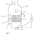
- FIG. 1 is an example of a detail of an exhaust system 1 of an internal combustion engine, not shown in detail, for example, a diesel engine, shown having an exhaust pipe 2, which goes off from the internal combustion engine, not shown.
- a housing 25 integrated, which is formed for example by a separate component in which a here only exemplary and schematically illustrated exhaust gas purification element 3 are arranged or integrated together with a rupture disk device 5.
- the housing-side branch channel 4 occluding rupture disk device and the exhaust gas purification element 3 are in this case arranged fluidically parallel, so that with an intact rupture disk device 5, the exhaust gas flows alone through the exhaust gas purification element 3.
- the exhaust gas purification element 3 may also be mounted centrally in the housing 25 and circumferentially surrounded by a correspondingly designed rupture disk device 5.
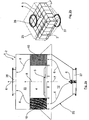
- Fig. 2a is shown, in which the branch duct 4 together with the rupture disk device 5 occluding this is arranged, for example, essentially centrally and / or centrally in the housing 25, so that the branch duct 4 is completely surrounded by a main flow duct 10.
- the branch channel 4 is here exemplarily annular along its entire longitudinal extension direction in the housing 25 surrounded by the arranged in the main flow channel exhaust gas purification element 3, in such a way that the branch channel 4 and the annular surrounding at least one exhaust gas purification element 3 or together the main flow channel 10 in a two housing portions 11, 12 are mutually separated common housing plane.
- the housing may have any arbitrary external geometry, for example, as shown, have a rectangular cross-section. However, it is of course also possible that the housing has a circular or cylindrical cross-section. Like also in the Fig. 2b indicated schematically, a plurality of different emission control elements 3 in the main flow channel 10, which surrounds the branch channel 4 may be arranged.
- the branch channel 4 and thus the rupture disc device closing this is arranged substantially in a rectilinear extension of a feed 27 of the exhaust gas into the housing 25 and a discharge 28 of the exhaust gas from the housing 25.
- This ensures that, for example, in conjunction with gas and dual-fuel engines as internal combustion engines, in an explosion in the exhaust system, the resulting pressure wave runs directly against the rupture disk device 5 and not against the arranged in the housing exhaust gas purification elements 3, whereby the latter be reliably protected against damage.
- a corresponding bursting pressure applied to the bursting disk device 5 the same breaks, so that then again, as in the embodiment according to Fig. 1 , At least a partial flow 7 can flow via the branch channel 4 (exhaust gas flow 8).
- the rupture disk device 5 closes in the mounted basic position an inflow-side mouth region of the branch channel 4, thereby ensuring that there is no undesirable turbulence and turbulence in the area in front of the rupture disk device 5.
- the rupture disk device 5 could also be located further downstream of the orifice opening thereof in the branching channel 4 (seen in the flow direction of the exhaust gas).
- branch duct 4 and the main flow duct 10 having the at least one exhaust gas purification element 3 again flow into a common housing region 11 downstream of the exhaust gas purification element 3, namely, as shown, in a direction to a discharge 28 of the exhaust gas from the housing 25 leading common housing portion 11 open.
- the housing wall portion of the housing 25 extending from the feeder 27 is initially funnel-shaped to direct the exhaust flow 6 in the desired manner toward the main flow passage 10.
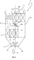
- FIG. 3 an embodiment of an exhaust system 1 according to the invention is shown, in which the branch channel 4 forms a parallel to a main flow channel 10 extending and substantially permeable by a partial flow 7 flow channel.
- One or more exhaust gas purification elements 3 are respectively arranged in the main flow channel 10 and in the branch channel 4, wherein the main flow channel side and the branch channel side exhaust gas purification element seen in the flow direction of the exhaust gas are spatially offset from each other such that the at least one branch channel side exhaust gas purification element 3 seen in the flow direction upstream of the at least one main flow channel side exhaust gas purification element 3 is located.
- the rupture disk device 5 is arranged here in a common wall region 29 of the main flow channel 10 and the branch channel 4 lying between the main flow channel side and branch channel side exhaust gas purification element 3.
- the inflowing exhaust gas stream 6 is divided immediately after the supply 27 to the main flow channel 10 and the branch channel 4, wherein the larger amount of exhaust gas flow through the main flow channel 10, because the upstream of the main flow channel side exhaust gas purification elements 3 upstream branch-side exhaust gas purification elements 3 here form a relatively high flow resistance, which causes just the larger amount of exhaust gas flows over the main flow channel 10.
- both the exhaust gas cleaning elements 3 arranged on the main flow channel side and the exhaust gas purification elements 3 located upstream thereto are correspondingly bypassed, so that the exhaust gas flow through the housing 25 can take place unhindered.
- the exhaust gas purification as in the Fig. 3 is shown schematically and dashed, optionally downstream of the rupture disk device 5 in the branch channel optionally at least one further emission control element 3 may be arranged.
- branch channel 4 and the main flow channel 10 thus open downstream of their respective exhaust gas purification elements 3 again in a common housing portion 11, which leads to a discharge 28 of the exhaust gas from the housing 25.
- the rupture disk device 5 can in principle be formed in different ways, such as by a conventional rupture disk or bursting disk, as for example in the DE 102 06 805 A1 is described.
- rupture disk device 5 A particularly preferred embodiment of the rupture disk device 5 will be described below in connection with FIGS Fig. 4 to 8 described in more detail:
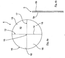
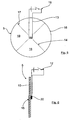
- the rupture disk device 5 as in the Fig. 4a and 4b represented by a single bursting plate or rupture disk to be formed, which has here only by way of example a circular outer geometry, but just as well, as for example in connection with the Fig. 2a and 2b the case would be any other suitable geometry, for example a rectangular outer geometry.
- the rupture disk device formed by a single rupture disk here has predetermined breaking points 14, and although in the form of the bursting disk wall not penetrating notches.
- These predetermined breaking points 14 form a defined predetermined breaking point pattern 17, according to which a plurality of spaced apart and extending from a central rupture disk 15 radially outward to the rupture disk edge 16 toward extending predetermined breaking points 14 are provided, each forming a predetermined breaking point line.
- These predetermined breaking point lines are in the circumferential direction of the rupture disk in each case, for example, uniformly spaced from each other, so that each rupture disk areas lying between two predetermined breaking line forms a displaceable or pivotable bursting disk wall segment 18.
- the rupture disk device 5 can also be formed by two rupture disks 5a, 5b which lie adjacent one another, preferably in a planar abutment connection and which are optionally dimensioned differently or designed differently.
- This electrical heating element 13 is arranged here by way of example centrally or centrally on the rupture disk device 5 formed here by a single rupture disk and causes the associated rupture disk wall region to be heated in the activated state of the electrical heating element 13 and thereby in particular thermally damaged or destroyed.
- the rupture disk of the rupture disk device 5 may again have the predetermined breaking points described above, so that after an initial damage or destruction of the middle rupture disk region 15 by the electric heating element 13 by then applied relatively high exhaust backpressure targeted displacement of the flap-like bursting disk wall segments 18 and thus a controlled release of the branch line 4 for the exhaust gas flow can take place.
- the electric heating element 13 is here coupled to the control device 19, which is shown only by way of example, which then controls the electrical heating element 13 when, generally speaking, it has been determined by means of at least one sensor that the exhaust gas flow 8 is to be released via the branch line 4.
- the differential pressure can be measured.
- temperature and / or NOx sensors can be used or their measurement results can be used to control the activation of the electric heating element 13 as a rupture aid.
- FIG. 2 The previously to Fig. 2 The same applies analogously to the one side view of a rupture disk direction 5 formed by a single rupture disk Fig. 6 in which the central or central rupture disk area 15 is assigned a blasting element 20 with an explosive charge which destroys the assigned bursting disk wall area in the activated state by igniting the explosive charge.
- the rupture aid is shown by way of example and schematically only on one side of the rupture disk, this can of course also be arranged on the other side. A mutual arrangement is also possible, as well as an arrangement of the bursting aids at different locations of the rupture disk.
- FIG. 7 In the sake of clarity greatly exaggerated drawn representation of Fig. 7 an embodiment is shown, in which two spaced apart or substantially parallel rupture discs 5a, 5b form a rupture disk device 5, which have between them, a free space 21 forming gap gap.
- the free space 21 can be charged by means of a feed device 22 with a gaseous (for example compressed air) or liquid (for example water) working medium as a bursting aid, so that a bursting pressure acting on the bursting disk walls from the free space 21 and thus from inside can be established in the Fig. 7 is shown in dashed lines. From a defined bursting pressure then burst the rupture disc assembly of the two rupture discs 5a, 5b, so that then the branch line 4, for example the exhaust gas flow 8 is released. Again, the feeder 22 is in turn driven by the control device 19 accordingly.
- a gaseous for example compressed air
- liquid for example water
- shut-off element 23 can be shut off. This means that ultimately the shut-off element 23 is actuated by means of the control device in order to allow the supply of the working medium, for example compressed air, into the free space 21.
- the double-walled rupture disk arrangement 5 should be designed here so that the supplied working medium can inflate the rupture disks 5a, 5b in the manner shown.
- a defined predetermined predetermined breaking point pattern can be formed in each case.
- Fig. 7 In conjunction with the double-walled rupture disk arrangement of Fig. 7 can of course also be provided between the rupture disks 5a, 5b, for example, substantially centrally and centrally to include or arrange other Berst Anlagenn, for example, the electric heating element 13 or the blasting element 20th
- This construction with a double-walled rupture disc arrangement has the particular advantage that the supply lines or valves or all further required components of the respective rupture aid can not get in contact with the exhaust gas.
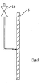
- FIG. 8 Another alternative embodiment is shown, in which the rupture disk device formed by a single rupture disk 5 is assigned a Druck Kunststoffzuclass Rhein 26 as a rupture aid, and preferably so that a mouth opening of the compressed air supply means 26 is directed substantially centrally of the rupture disk.
- the compressed air supply means 26 can then be suitably controlled (and in an analogous manner to the previous embodiments) of the control device 19 not shown here one or more compressed air pulses and / or shocks, preferably applied interval or pulse-like manner on the rupture disk and thus destroyed. It is understood that the compressed air supply means 26 can be shut off by means of a shut-off element 23.
Landscapes
- Engineering & Computer Science (AREA)
- Chemical & Material Sciences (AREA)
- Combustion & Propulsion (AREA)
- Mechanical Engineering (AREA)
- General Engineering & Computer Science (AREA)
- Exhaust Gas After Treatment (AREA)
- Processes For Solid Components From Exhaust (AREA)
- Exhaust Silencers (AREA)
Applications Claiming Priority (1)
| Application Number | Priority Date | Filing Date | Title |
|---|---|---|---|
| DE102014009265.8A DE102014009265A1 (de) | 2014-06-25 | 2014-06-25 | Abgasanlage für Brennkraftmaschinen |
Publications (2)
| Publication Number | Publication Date |
|---|---|
| EP2960452A1 EP2960452A1 (de) | 2015-12-30 |
| EP2960452B1 true EP2960452B1 (de) | 2017-04-05 |
Family
ID=52394891
Family Applications (1)
| Application Number | Title | Priority Date | Filing Date |
|---|---|---|---|
| EP15000204.6A Active EP2960452B1 (de) | 2014-06-25 | 2015-01-23 | Abgasanlage für Brennkraftmaschinen |
Country Status (5)
| Country | Link |
|---|---|
| EP (1) | EP2960452B1 (da) |
| KR (1) | KR102488702B1 (da) |
| CN (1) | CN105221225B (da) |
| DE (1) | DE102014009265A1 (da) |
| DK (1) | DK2960452T3 (da) |
Families Citing this family (1)
| Publication number | Priority date | Publication date | Assignee | Title |
|---|---|---|---|---|
| CN109209586A (zh) * | 2017-07-03 | 2019-01-15 | 江苏今道投资发展有限公司 | 一种汽车尾气排放监测装置 |
Family Cites Families (8)
| Publication number | Priority date | Publication date | Assignee | Title |
|---|---|---|---|---|
| US4625511A (en) * | 1984-08-13 | 1986-12-02 | Arvin Industries, Inc. | Exhaust processor |
| DE4002754C2 (de) * | 1990-01-31 | 1994-03-17 | Daimler Benz Ag | Im Zuluftstrom einer Heiz- oder Klimaanlage eines Kraftwagens eingesetzte Filteranordnung |
| US5377716A (en) * | 1993-08-16 | 1995-01-03 | Bs&B Safety Systems, Inc. | Pressure surge resistant rupture disk assembly |
| DE10000921B4 (de) * | 2000-01-12 | 2012-03-01 | Volkswagen Ag | Partikelfiltersystem, insbesondere für Dieselmotoren |
| DE10206805A1 (de) | 2002-02-19 | 2003-08-28 | Bosch Gmbh Robert | Russfilter und Verfahren zur Reinigung von Abgasen |
| WO2004002764A1 (de) * | 2002-06-27 | 2004-01-08 | Luk Fahrzeugh-Hydraulik Gmbh & Co. Kg | Klimaanlage mit berstscheibeneinrichtung |
| DE102005038707A1 (de) * | 2005-08-15 | 2007-03-08 | Emitec Gesellschaft Für Emissionstechnologie Mbh | Verfahren und Vorrichtung zur Aufbereitung eines Abgases einer Verbrennungskraftmaschine |
| WO2013063137A1 (en) * | 2011-10-26 | 2013-05-02 | Boshart Automotive Testing Service, Inc. | Over temperature / pressure safety device for diesel particulate filters |
-
2014
- 2014-06-25 DE DE102014009265.8A patent/DE102014009265A1/de active Pending
-
2015
- 2015-01-23 EP EP15000204.6A patent/EP2960452B1/de active Active
- 2015-01-23 DK DK15000204.6T patent/DK2960452T3/da active
- 2015-04-24 KR KR1020150057865A patent/KR102488702B1/ko active Active
- 2015-06-25 CN CN201510355906.XA patent/CN105221225B/zh active Active
Non-Patent Citations (1)
| Title |
|---|
| None * |
Also Published As
| Publication number | Publication date |
|---|---|
| KR102488702B1 (ko) | 2023-01-17 |
| EP2960452A1 (de) | 2015-12-30 |
| DE102014009265A1 (de) | 2015-12-31 |
| CN105221225B (zh) | 2020-01-17 |
| CN105221225A (zh) | 2016-01-06 |
| KR20160000832A (ko) | 2016-01-05 |
| DK2960452T3 (da) | 2017-07-17 |
Similar Documents
| Publication | Publication Date | Title |
|---|---|---|
| DE112013000011B4 (de) | Mischvorrichtung für eine wässrige Reduktionsmittellösung und Abgasnachbehandlungsvorrichtung, die mit derselben versehen ist | |
| EP3346103B1 (de) | Abgasanlage | |
| DE202014009592U1 (de) | Abgasbehandlungseinrichtung zur Behandlung von Abgas einer Brennkraftmaschine und Brennkraftmaschine | |
| EP2960450B1 (de) | Abgasanlage für Brennkraftmaschinen | |
| EP2960452B1 (de) | Abgasanlage für Brennkraftmaschinen | |
| EP2960451B1 (de) | Abgasanlage für Brennkraftmaschinen | |
| EP1490586B1 (de) | Russfilter und verfahren zur reinigung von abgasen | |
| DE19629627C2 (de) | Sicherheitsvorrichtung zur Vermeidung des Kraftstoffaustritts | |
| DE102011081569A1 (de) | Vorrichtung zur Aufteilung eines Gesamtluftstroms zum Betrieb eines Abgasbrenners mit einem inneren und einem äußeren Brennraum | |
| DE10202005B4 (de) | Filtereinrichtung | |
| DE10000921B4 (de) | Partikelfiltersystem, insbesondere für Dieselmotoren | |
| DE102017101923A1 (de) | Abgasanlage | |
| EP1715162B1 (de) | Abgasabführungssystem für eine Brennkraftmaschine sowie Absperrklappe für ein Abgasabführungssystem | |
| WO2019185555A1 (de) | Vorrichtung zur entfeuchtung einer drucksensorzuleitung eines partikelfilters sowie kraftfahrzeug mit einer solchen | |
| EP2611999A1 (de) | Rohr | |
| DE102009058379A1 (de) | Verbrennungskraftmaschine | |
| DE102007036254A1 (de) | Abgasanlage einer Brennkraftmaschine | |
| DE102007063100A1 (de) | Abgasnachbehandlungseinrichtung mit mindestens zwei Partikelfiltern | |
| EP2796680B1 (de) | Abgasanlage einer Brennkraftmaschine | |
| EP1553268B1 (de) | Filtereinrichtung, insbesondere für eine Abgasanlage einer Brennkraftmaschine | |
| DE102010008273B4 (de) | Partikelfilteranordnung | |
| WO2007025959A1 (de) | Partikelfilter mit einrichtung zur vermeidung der filterverblockung | |
| EP2798166B1 (de) | Dosiermodul und abgasnachbehandlungseinrichtung | |
| WO2016030007A1 (de) | Diffusor für einen gasgenerator, gasgenerator, gassackmodul und fahrzeugsicherheitssystem mit einem solchen diffusor | |
| DE102014208940A1 (de) | Abgaspartikel-Filtersystem für einen Verbrennungsmotor in der beispielhaften Ausgestaltung als Dieselmotor sowie Fahrzeugantrieb nebst entsprechend ausgestattetem Fahrzeug |
Legal Events
| Date | Code | Title | Description |
|---|---|---|---|
| PUAI | Public reference made under article 153(3) epc to a published international application that has entered the european phase |
Free format text: ORIGINAL CODE: 0009012 |
|
| AK | Designated contracting states |
Kind code of ref document: A1 Designated state(s): AL AT BE BG CH CY CZ DE DK EE ES FI FR GB GR HR HU IE IS IT LI LT LU LV MC MK MT NL NO PL PT RO RS SE SI SK SM TR |
|
| AX | Request for extension of the european patent |
Extension state: BA ME |
|
| 17P | Request for examination filed |
Effective date: 20160629 |
|
| GRAP | Despatch of communication of intention to grant a patent |
Free format text: ORIGINAL CODE: EPIDOSNIGR1 |
|
| INTG | Intention to grant announced |
Effective date: 20161025 |
|
| GRAS | Grant fee paid |
Free format text: ORIGINAL CODE: EPIDOSNIGR3 |
|
| GRAA | (expected) grant |
Free format text: ORIGINAL CODE: 0009210 |
|
| AK | Designated contracting states |
Kind code of ref document: B1 Designated state(s): AL AT BE BG CH CY CZ DE DK EE ES FI FR GB GR HR HU IE IS IT LI LT LU LV MC MK MT NL NO PL PT RO RS SE SI SK SM TR |
|
| REG | Reference to a national code |
Ref country code: GB Ref legal event code: FG4D Free format text: NOT ENGLISH |
|
| REG | Reference to a national code |
Ref country code: CH Ref legal event code: EP |
|
| REG | Reference to a national code |
Ref country code: AT Ref legal event code: REF Ref document number: 882055 Country of ref document: AT Kind code of ref document: T Effective date: 20170415 |
|
| REG | Reference to a national code |
Ref country code: NL Ref legal event code: FP |
|
| REG | Reference to a national code |
Ref country code: IE Ref legal event code: FG4D Free format text: LANGUAGE OF EP DOCUMENT: GERMAN |
|
| REG | Reference to a national code |
Ref country code: DE Ref legal event code: R096 Ref document number: 502015000784 Country of ref document: DE |
|
| REG | Reference to a national code |
Ref country code: DK Ref legal event code: T3 Effective date: 20170706 |
|
| REG | Reference to a national code |
Ref country code: SE Ref legal event code: TRGR |
|
| REG | Reference to a national code |
Ref country code: LT Ref legal event code: MG4D |
|
| PG25 | Lapsed in a contracting state [announced via postgrant information from national office to epo] |
Ref country code: HR Free format text: LAPSE BECAUSE OF FAILURE TO SUBMIT A TRANSLATION OF THE DESCRIPTION OR TO PAY THE FEE WITHIN THE PRESCRIBED TIME-LIMIT Effective date: 20170405 Ref country code: NO Free format text: LAPSE BECAUSE OF FAILURE TO SUBMIT A TRANSLATION OF THE DESCRIPTION OR TO PAY THE FEE WITHIN THE PRESCRIBED TIME-LIMIT Effective date: 20170705 Ref country code: FI Free format text: LAPSE BECAUSE OF FAILURE TO SUBMIT A TRANSLATION OF THE DESCRIPTION OR TO PAY THE FEE WITHIN THE PRESCRIBED TIME-LIMIT Effective date: 20170405 Ref country code: GR Free format text: LAPSE BECAUSE OF FAILURE TO SUBMIT A TRANSLATION OF THE DESCRIPTION OR TO PAY THE FEE WITHIN THE PRESCRIBED TIME-LIMIT Effective date: 20170706 Ref country code: LT Free format text: LAPSE BECAUSE OF FAILURE TO SUBMIT A TRANSLATION OF THE DESCRIPTION OR TO PAY THE FEE WITHIN THE PRESCRIBED TIME-LIMIT Effective date: 20170405 Ref country code: ES Free format text: LAPSE BECAUSE OF FAILURE TO SUBMIT A TRANSLATION OF THE DESCRIPTION OR TO PAY THE FEE WITHIN THE PRESCRIBED TIME-LIMIT Effective date: 20170405 |
|
| PG25 | Lapsed in a contracting state [announced via postgrant information from national office to epo] |
Ref country code: BG Free format text: LAPSE BECAUSE OF FAILURE TO SUBMIT A TRANSLATION OF THE DESCRIPTION OR TO PAY THE FEE WITHIN THE PRESCRIBED TIME-LIMIT Effective date: 20170705 Ref country code: IS Free format text: LAPSE BECAUSE OF FAILURE TO SUBMIT A TRANSLATION OF THE DESCRIPTION OR TO PAY THE FEE WITHIN THE PRESCRIBED TIME-LIMIT Effective date: 20170805 Ref country code: RS Free format text: LAPSE BECAUSE OF FAILURE TO SUBMIT A TRANSLATION OF THE DESCRIPTION OR TO PAY THE FEE WITHIN THE PRESCRIBED TIME-LIMIT Effective date: 20170405 Ref country code: LV Free format text: LAPSE BECAUSE OF FAILURE TO SUBMIT A TRANSLATION OF THE DESCRIPTION OR TO PAY THE FEE WITHIN THE PRESCRIBED TIME-LIMIT Effective date: 20170405 Ref country code: PL Free format text: LAPSE BECAUSE OF FAILURE TO SUBMIT A TRANSLATION OF THE DESCRIPTION OR TO PAY THE FEE WITHIN THE PRESCRIBED TIME-LIMIT Effective date: 20170405 |
|
| REG | Reference to a national code |
Ref country code: DE Ref legal event code: R097 Ref document number: 502015000784 Country of ref document: DE |
|
| REG | Reference to a national code |
Ref country code: FR Ref legal event code: PLFP Year of fee payment: 4 |
|
| PG25 | Lapsed in a contracting state [announced via postgrant information from national office to epo] |
Ref country code: RO Free format text: LAPSE BECAUSE OF FAILURE TO SUBMIT A TRANSLATION OF THE DESCRIPTION OR TO PAY THE FEE WITHIN THE PRESCRIBED TIME-LIMIT Effective date: 20170405 Ref country code: EE Free format text: LAPSE BECAUSE OF FAILURE TO SUBMIT A TRANSLATION OF THE DESCRIPTION OR TO PAY THE FEE WITHIN THE PRESCRIBED TIME-LIMIT Effective date: 20170405 Ref country code: CZ Free format text: LAPSE BECAUSE OF FAILURE TO SUBMIT A TRANSLATION OF THE DESCRIPTION OR TO PAY THE FEE WITHIN THE PRESCRIBED TIME-LIMIT Effective date: 20170405 Ref country code: SK Free format text: LAPSE BECAUSE OF FAILURE TO SUBMIT A TRANSLATION OF THE DESCRIPTION OR TO PAY THE FEE WITHIN THE PRESCRIBED TIME-LIMIT Effective date: 20170405 |
|
| PLBE | No opposition filed within time limit |
Free format text: ORIGINAL CODE: 0009261 |
|
| STAA | Information on the status of an ep patent application or granted ep patent |
Free format text: STATUS: NO OPPOSITION FILED WITHIN TIME LIMIT |
|
| PG25 | Lapsed in a contracting state [announced via postgrant information from national office to epo] |
Ref country code: SM Free format text: LAPSE BECAUSE OF FAILURE TO SUBMIT A TRANSLATION OF THE DESCRIPTION OR TO PAY THE FEE WITHIN THE PRESCRIBED TIME-LIMIT Effective date: 20170405 |
|
| 26N | No opposition filed |
Effective date: 20180108 |
|
| PG25 | Lapsed in a contracting state [announced via postgrant information from national office to epo] |
Ref country code: SI Free format text: LAPSE BECAUSE OF FAILURE TO SUBMIT A TRANSLATION OF THE DESCRIPTION OR TO PAY THE FEE WITHIN THE PRESCRIBED TIME-LIMIT Effective date: 20170405 |
|
| REG | Reference to a national code |
Ref country code: CH Ref legal event code: PL |
|
| PG25 | Lapsed in a contracting state [announced via postgrant information from national office to epo] |
Ref country code: MT Free format text: LAPSE BECAUSE OF FAILURE TO SUBMIT A TRANSLATION OF THE DESCRIPTION OR TO PAY THE FEE WITHIN THE PRESCRIBED TIME-LIMIT Effective date: 20170405 |
|
| PG25 | Lapsed in a contracting state [announced via postgrant information from national office to epo] |
Ref country code: LU Free format text: LAPSE BECAUSE OF NON-PAYMENT OF DUE FEES Effective date: 20180123 |
|
| REG | Reference to a national code |
Ref country code: IE Ref legal event code: MM4A |
|
| REG | Reference to a national code |
Ref country code: BE Ref legal event code: MM Effective date: 20180131 |
|
| PG25 | Lapsed in a contracting state [announced via postgrant information from national office to epo] |
Ref country code: LI Free format text: LAPSE BECAUSE OF NON-PAYMENT OF DUE FEES Effective date: 20180131 Ref country code: CH Free format text: LAPSE BECAUSE OF NON-PAYMENT OF DUE FEES Effective date: 20180131 Ref country code: BE Free format text: LAPSE BECAUSE OF NON-PAYMENT OF DUE FEES Effective date: 20180131 |
|
| PG25 | Lapsed in a contracting state [announced via postgrant information from national office to epo] |
Ref country code: IE Free format text: LAPSE BECAUSE OF NON-PAYMENT OF DUE FEES Effective date: 20180123 |
|
| PG25 | Lapsed in a contracting state [announced via postgrant information from national office to epo] |
Ref country code: MC Free format text: LAPSE BECAUSE OF FAILURE TO SUBMIT A TRANSLATION OF THE DESCRIPTION OR TO PAY THE FEE WITHIN THE PRESCRIBED TIME-LIMIT Effective date: 20170405 |
|
| GBPC | Gb: european patent ceased through non-payment of renewal fee |
Effective date: 20190123 |
|
| REG | Reference to a national code |
Ref country code: DE Ref legal event code: R081 Ref document number: 502015000784 Country of ref document: DE Owner name: MAN TRUCK & BUS SE, DE Free format text: FORMER OWNER: MAN TRUCK & BUS AG, 80995 MUENCHEN, DE |
|
| PG25 | Lapsed in a contracting state [announced via postgrant information from national office to epo] |
Ref country code: GB Free format text: LAPSE BECAUSE OF NON-PAYMENT OF DUE FEES Effective date: 20190123 |
|
| PG25 | Lapsed in a contracting state [announced via postgrant information from national office to epo] |
Ref country code: TR Free format text: LAPSE BECAUSE OF FAILURE TO SUBMIT A TRANSLATION OF THE DESCRIPTION OR TO PAY THE FEE WITHIN THE PRESCRIBED TIME-LIMIT Effective date: 20170405 |
|
| PG25 | Lapsed in a contracting state [announced via postgrant information from national office to epo] |
Ref country code: PT Free format text: LAPSE BECAUSE OF FAILURE TO SUBMIT A TRANSLATION OF THE DESCRIPTION OR TO PAY THE FEE WITHIN THE PRESCRIBED TIME-LIMIT Effective date: 20170405 |
|
| PG25 | Lapsed in a contracting state [announced via postgrant information from national office to epo] |
Ref country code: MK Free format text: LAPSE BECAUSE OF NON-PAYMENT OF DUE FEES Effective date: 20170405 Ref country code: CY Free format text: LAPSE BECAUSE OF FAILURE TO SUBMIT A TRANSLATION OF THE DESCRIPTION OR TO PAY THE FEE WITHIN THE PRESCRIBED TIME-LIMIT Effective date: 20170405 Ref country code: HU Free format text: LAPSE BECAUSE OF FAILURE TO SUBMIT A TRANSLATION OF THE DESCRIPTION OR TO PAY THE FEE WITHIN THE PRESCRIBED TIME-LIMIT; INVALID AB INITIO Effective date: 20150123 |
|
| PG25 | Lapsed in a contracting state [announced via postgrant information from national office to epo] |
Ref country code: AL Free format text: LAPSE BECAUSE OF FAILURE TO SUBMIT A TRANSLATION OF THE DESCRIPTION OR TO PAY THE FEE WITHIN THE PRESCRIBED TIME-LIMIT Effective date: 20170405 |
|
| REG | Reference to a national code |
Ref country code: AT Ref legal event code: MM01 Ref document number: 882055 Country of ref document: AT Kind code of ref document: T Effective date: 20200123 |
|
| PG25 | Lapsed in a contracting state [announced via postgrant information from national office to epo] |
Ref country code: AT Free format text: LAPSE BECAUSE OF NON-PAYMENT OF DUE FEES Effective date: 20200123 |
|
| PGFP | Annual fee paid to national office [announced via postgrant information from national office to epo] |
Ref country code: NL Payment date: 20260122 Year of fee payment: 12 |
|
| PGFP | Annual fee paid to national office [announced via postgrant information from national office to epo] |
Ref country code: SE Payment date: 20260126 Year of fee payment: 12 |
|
| PGFP | Annual fee paid to national office [announced via postgrant information from national office to epo] |
Ref country code: DE Payment date: 20260127 Year of fee payment: 12 Ref country code: DK Payment date: 20260123 Year of fee payment: 12 |
|
| PGFP | Annual fee paid to national office [announced via postgrant information from national office to epo] |
Ref country code: IT Payment date: 20260123 Year of fee payment: 12 |
|
| PGFP | Annual fee paid to national office [announced via postgrant information from national office to epo] |
Ref country code: FR Payment date: 20260127 Year of fee payment: 12 |