EP2960456A1 - Dispositif de traitement de gaz d'echappement compact et angulaire - Google Patents
Dispositif de traitement de gaz d'echappement compact et angulaire Download PDFInfo
- Publication number
- EP2960456A1 EP2960456A1 EP14174777.4A EP14174777A EP2960456A1 EP 2960456 A1 EP2960456 A1 EP 2960456A1 EP 14174777 A EP14174777 A EP 14174777A EP 2960456 A1 EP2960456 A1 EP 2960456A1
- Authority
- EP
- European Patent Office
- Prior art keywords
- catalytic substrate
- exhaust gas
- aftertreatment device
- gas aftertreatment
- catalytic
- Prior art date
- Legal status (The legal status is an assumption and is not a legal conclusion. Google has not performed a legal analysis and makes no representation as to the accuracy of the status listed.)
- Granted
Links
Images

Classifications
-
- F—MECHANICAL ENGINEERING; LIGHTING; HEATING; WEAPONS; BLASTING
- F01—MACHINES OR ENGINES IN GENERAL; ENGINE PLANTS IN GENERAL; STEAM ENGINES
- F01N—GAS-FLOW SILENCERS OR EXHAUST APPARATUS FOR MACHINES OR ENGINES IN GENERAL; GAS-FLOW SILENCERS OR EXHAUST APPARATUS FOR INTERNAL-COMBUSTION ENGINES
- F01N3/00—Exhaust or silencing apparatus having means for purifying, rendering innocuous, or otherwise treating exhaust
- F01N3/08—Exhaust or silencing apparatus having means for purifying, rendering innocuous, or otherwise treating exhaust for rendering innocuous
- F01N3/10—Exhaust or silencing apparatus having means for purifying, rendering innocuous, or otherwise treating exhaust for rendering innocuous by thermal or catalytic conversion of noxious components of exhaust
- F01N3/24—Exhaust or silencing apparatus having means for purifying, rendering innocuous, or otherwise treating exhaust for rendering innocuous by thermal or catalytic conversion of noxious components of exhaust characterised by constructional aspects of converting apparatus
- F01N3/28—Construction of catalytic reactors
- F01N3/2892—Exhaust flow directors or the like, e.g. upstream of catalytic device
-
- B—PERFORMING OPERATIONS; TRANSPORTING
- B01—PHYSICAL OR CHEMICAL PROCESSES OR APPARATUS IN GENERAL
- B01D—SEPARATION
- B01D53/00—Separation of gases or vapours; Recovering vapours of volatile solvents from gases; Chemical or biological purification of waste gases, e.g. engine exhaust gases, smoke, fumes, flue gases, aerosols
- B01D53/34—Chemical or biological purification of waste gases
- B01D53/92—Chemical or biological purification of waste gases of engine exhaust gases
- B01D53/94—Chemical or biological purification of waste gases of engine exhaust gases by catalytic processes
- B01D53/9459—Removing one or more of nitrogen oxides, carbon monoxide, or hydrocarbons by multiple successive catalytic functions; systems with more than one different function, e.g. zone coated catalysts
- B01D53/9477—Removing one or more of nitrogen oxides, carbon monoxide, or hydrocarbons by multiple successive catalytic functions; systems with more than one different function, e.g. zone coated catalysts with catalysts positioned on separate bricks, e.g. exhaust systems
-
- F—MECHANICAL ENGINEERING; LIGHTING; HEATING; WEAPONS; BLASTING
- F01—MACHINES OR ENGINES IN GENERAL; ENGINE PLANTS IN GENERAL; STEAM ENGINES
- F01N—GAS-FLOW SILENCERS OR EXHAUST APPARATUS FOR MACHINES OR ENGINES IN GENERAL; GAS-FLOW SILENCERS OR EXHAUST APPARATUS FOR INTERNAL-COMBUSTION ENGINES
- F01N13/00—Exhaust or silencing apparatus characterised by constructional features
- F01N13/009—Exhaust or silencing apparatus characterised by constructional features having two or more separate purifying devices arranged in series
-
- F—MECHANICAL ENGINEERING; LIGHTING; HEATING; WEAPONS; BLASTING
- F01—MACHINES OR ENGINES IN GENERAL; ENGINE PLANTS IN GENERAL; STEAM ENGINES
- F01N—GAS-FLOW SILENCERS OR EXHAUST APPARATUS FOR MACHINES OR ENGINES IN GENERAL; GAS-FLOW SILENCERS OR EXHAUST APPARATUS FOR INTERNAL-COMBUSTION ENGINES
- F01N13/00—Exhaust or silencing apparatus characterised by constructional features
- F01N13/009—Exhaust or silencing apparatus characterised by constructional features having two or more separate purifying devices arranged in series
- F01N13/0097—Exhaust or silencing apparatus characterised by constructional features having two or more separate purifying devices arranged in series the purifying devices are arranged in a single housing
-
- F—MECHANICAL ENGINEERING; LIGHTING; HEATING; WEAPONS; BLASTING
- F01—MACHINES OR ENGINES IN GENERAL; ENGINE PLANTS IN GENERAL; STEAM ENGINES
- F01N—GAS-FLOW SILENCERS OR EXHAUST APPARATUS FOR MACHINES OR ENGINES IN GENERAL; GAS-FLOW SILENCERS OR EXHAUST APPARATUS FOR INTERNAL-COMBUSTION ENGINES
- F01N3/00—Exhaust or silencing apparatus having means for purifying, rendering innocuous, or otherwise treating exhaust
- F01N3/08—Exhaust or silencing apparatus having means for purifying, rendering innocuous, or otherwise treating exhaust for rendering innocuous
- F01N3/10—Exhaust or silencing apparatus having means for purifying, rendering innocuous, or otherwise treating exhaust for rendering innocuous by thermal or catalytic conversion of noxious components of exhaust
- F01N3/105—General auxiliary catalysts, e.g. upstream or downstream of the main catalyst
- F01N3/108—Auxiliary reduction catalysts
-
- F—MECHANICAL ENGINEERING; LIGHTING; HEATING; WEAPONS; BLASTING
- F01—MACHINES OR ENGINES IN GENERAL; ENGINE PLANTS IN GENERAL; STEAM ENGINES
- F01N—GAS-FLOW SILENCERS OR EXHAUST APPARATUS FOR MACHINES OR ENGINES IN GENERAL; GAS-FLOW SILENCERS OR EXHAUST APPARATUS FOR INTERNAL-COMBUSTION ENGINES
- F01N3/00—Exhaust or silencing apparatus having means for purifying, rendering innocuous, or otherwise treating exhaust
- F01N3/08—Exhaust or silencing apparatus having means for purifying, rendering innocuous, or otherwise treating exhaust for rendering innocuous
- F01N3/10—Exhaust or silencing apparatus having means for purifying, rendering innocuous, or otherwise treating exhaust for rendering innocuous by thermal or catalytic conversion of noxious components of exhaust
- F01N3/18—Exhaust or silencing apparatus having means for purifying, rendering innocuous, or otherwise treating exhaust for rendering innocuous by thermal or catalytic conversion of noxious components of exhaust characterised by methods of operation; Control
- F01N3/20—Exhaust or silencing apparatus having means for purifying, rendering innocuous, or otherwise treating exhaust for rendering innocuous by thermal or catalytic conversion of noxious components of exhaust characterised by methods of operation; Control specially adapted for catalytic conversion
- F01N3/206—Adding periodically or continuously substances to exhaust gases for promoting purification, e.g. catalytic material in liquid form, NOx reducing agents
- F01N3/2066—Selective catalytic reduction [SCR]
-
- B—PERFORMING OPERATIONS; TRANSPORTING
- B01—PHYSICAL OR CHEMICAL PROCESSES OR APPARATUS IN GENERAL
- B01D—SEPARATION
- B01D2255/00—Catalysts
- B01D2255/90—Physical characteristics of catalysts
- B01D2255/904—Multiple catalysts
-
- F—MECHANICAL ENGINEERING; LIGHTING; HEATING; WEAPONS; BLASTING
- F01—MACHINES OR ENGINES IN GENERAL; ENGINE PLANTS IN GENERAL; STEAM ENGINES
- F01N—GAS-FLOW SILENCERS OR EXHAUST APPARATUS FOR MACHINES OR ENGINES IN GENERAL; GAS-FLOW SILENCERS OR EXHAUST APPARATUS FOR INTERNAL-COMBUSTION ENGINES
- F01N2240/00—Combination or association of two or more different exhaust treating devices, or of at least one such device with an auxiliary device, not covered by indexing codes F01N2230/00 or F01N2250/00, one of the devices being
- F01N2240/20—Combination or association of two or more different exhaust treating devices, or of at least one such device with an auxiliary device, not covered by indexing codes F01N2230/00 or F01N2250/00, one of the devices being a flow director or deflector
-
- F—MECHANICAL ENGINEERING; LIGHTING; HEATING; WEAPONS; BLASTING
- F01—MACHINES OR ENGINES IN GENERAL; ENGINE PLANTS IN GENERAL; STEAM ENGINES
- F01N—GAS-FLOW SILENCERS OR EXHAUST APPARATUS FOR MACHINES OR ENGINES IN GENERAL; GAS-FLOW SILENCERS OR EXHAUST APPARATUS FOR INTERNAL-COMBUSTION ENGINES
- F01N2470/00—Structure or shape of exhaust gas passages, pipes or tubes
- F01N2470/24—Concentric tubes or tubes being concentric to housing, e.g. telescopically assembled
-
- F—MECHANICAL ENGINEERING; LIGHTING; HEATING; WEAPONS; BLASTING
- F01—MACHINES OR ENGINES IN GENERAL; ENGINE PLANTS IN GENERAL; STEAM ENGINES
- F01N—GAS-FLOW SILENCERS OR EXHAUST APPARATUS FOR MACHINES OR ENGINES IN GENERAL; GAS-FLOW SILENCERS OR EXHAUST APPARATUS FOR INTERNAL-COMBUSTION ENGINES
- F01N2490/00—Structure, disposition or shape of gas-chambers
- F01N2490/02—Two or more expansion chambers in series connected by means of tubes
- F01N2490/06—Two or more expansion chambers in series connected by means of tubes the gases flowing longitudinally from inlet to outlet in opposite directions
-
- F—MECHANICAL ENGINEERING; LIGHTING; HEATING; WEAPONS; BLASTING
- F01—MACHINES OR ENGINES IN GENERAL; ENGINE PLANTS IN GENERAL; STEAM ENGINES
- F01N—GAS-FLOW SILENCERS OR EXHAUST APPARATUS FOR MACHINES OR ENGINES IN GENERAL; GAS-FLOW SILENCERS OR EXHAUST APPARATUS FOR INTERNAL-COMBUSTION ENGINES
- F01N2510/00—Surface coverings
- F01N2510/06—Surface coverings for exhaust purification, e.g. catalytic reaction
-
- F—MECHANICAL ENGINEERING; LIGHTING; HEATING; WEAPONS; BLASTING
- F01—MACHINES OR ENGINES IN GENERAL; ENGINE PLANTS IN GENERAL; STEAM ENGINES
- F01N—GAS-FLOW SILENCERS OR EXHAUST APPARATUS FOR MACHINES OR ENGINES IN GENERAL; GAS-FLOW SILENCERS OR EXHAUST APPARATUS FOR INTERNAL-COMBUSTION ENGINES
- F01N2610/00—Adding substances to exhaust gases
- F01N2610/14—Arrangements for the supply of substances, e.g. conduits
- F01N2610/1453—Sprayers or atomisers; Arrangement thereof in the exhaust apparatus
-
- Y—GENERAL TAGGING OF NEW TECHNOLOGICAL DEVELOPMENTS; GENERAL TAGGING OF CROSS-SECTIONAL TECHNOLOGIES SPANNING OVER SEVERAL SECTIONS OF THE IPC; TECHNICAL SUBJECTS COVERED BY FORMER USPC CROSS-REFERENCE ART COLLECTIONS [XRACs] AND DIGESTS
- Y02—TECHNOLOGIES OR APPLICATIONS FOR MITIGATION OR ADAPTATION AGAINST CLIMATE CHANGE
- Y02A—TECHNOLOGIES FOR ADAPTATION TO CLIMATE CHANGE
- Y02A50/00—TECHNOLOGIES FOR ADAPTATION TO CLIMATE CHANGE in human health protection, e.g. against extreme weather
- Y02A50/20—Air quality improvement or preservation, e.g. vehicle emission control or emission reduction by using catalytic converters
-
- Y—GENERAL TAGGING OF NEW TECHNOLOGICAL DEVELOPMENTS; GENERAL TAGGING OF CROSS-SECTIONAL TECHNOLOGIES SPANNING OVER SEVERAL SECTIONS OF THE IPC; TECHNICAL SUBJECTS COVERED BY FORMER USPC CROSS-REFERENCE ART COLLECTIONS [XRACs] AND DIGESTS
- Y02—TECHNOLOGIES OR APPLICATIONS FOR MITIGATION OR ADAPTATION AGAINST CLIMATE CHANGE
- Y02T—CLIMATE CHANGE MITIGATION TECHNOLOGIES RELATED TO TRANSPORTATION
- Y02T10/00—Road transport of goods or passengers
- Y02T10/10—Internal combustion engine [ICE] based vehicles
- Y02T10/12—Improving ICE efficiencies
Definitions
- the present invention relates to an exhaust gas aftertreatment device for an internal combustion engine.
- the invention can be applied in passenger cars as well as in heavy duty vehicles such as trucks or buses.
- an exhaust gas aftertreatment device comprising at least one catalytic converter substrate.
- a catalytic substrate generally comprises a channelled structure which exhaust gas can pass through while being exposed to the large surface area of the catalytic substrate.
- the channels of the catalytic substrates may be fluidly connected by perforating holes or like allowing gas to pass between adjacent channels. This enables gas to diffuse through the catalytic substrate structure.
- TWC Three Way Catalyst
- DOC Diesel Oxidation Catalyst
- LNT Lean NOx Trap
- the TWC or the DOC/LNT is supplemented by a catalytic substrate with Selective Catalytic Reduction (SCR) functionality for improved NOx reduction.
- SCR Selective Catalytic Reduction
- a catalytic substrate of SCR type a liquid or gaseous reductant is added to the exhaust gas emission flow before the exhaust gas enters the catalytic substrate of SCR type.
- reductant enables the catalytic reduction were NOx is reduced to diatomic nitrogen, N2, and water, H2O.
- Catalytic substrates combining the functionalities of more than one type of catalytic substrate in one catalytic substrate also exist.
- exhaust gas aftertreatment devices often are associated with design restrains due to the limited available space in the engine compartment.
- small exhaust gas aftertreatment devices are preferred from an engine packaging perspective, but small exhaust gas aftertreatment devices usually means that the flow distance between the inlet and the catalytic substrates of the exhaust gas aftertreatment device is limited. Limited distance means that the time and distance during which mixing of the exhaust gas emissions can occur is limited. Insufficient mixing of the exhaust gas emissions gives inhomogeneous exhaust gas emission mixture. This might e.g. be problematic for emission gas sensors, arranged in the exhaust gas emission flow, to work properly and give accurate emission measurements.
- the evaporation of injected reductant is also benefitted by long distance between the injection of reductant and the subsequently provided catalytic converter of SCR type such that the injected reductant can be exposed to hot exhaust gas for a longer period of time.
- compact design directly contradicts other desirable properties of the exhaust gas aftertreatment device such as sufficient mixing.
- US 2008/0041036 A1 discloses a method for adding at least one, in particular liquid, reactant to an exhaust gas stream of an internal combustion engine and a device for treating an exhaust gas stream of an internal combustion engine.
- an element wherein said element may be a particulate filter or catalyst body, is arranged in an exhaust gas flow. Downstream of said element a nozzle may be provided spraying reactant flow onto the element such that a coating covering preferably at least 10% of the length of the element is formed.
- the exhaust gas flow subsequently is redirected at a reversal region such that the exhaust gas flow is redirected to flow substantially opposite the entering exhaust gas flow before being discharged from the device.
- the device disclosed in US 2008/0041036 A1 has many advantages but is only provided with one catalytic substrate. Additionally US 2008/0041036 A1 fails to provide sufficient mixing of reactant and exhaust gas.
- An object of the present invention is to provide a compact exhaust gas aftertreatment device, in particular a compact exhaust gas aftertreatment device with improved catalytic properties due to improved mixing and reductant evaporation characteristics.
- the object is achieved by an exhaust gas aftertreatment device according to claim 1.
- Said exhaust gas aftertreatment device is provided in order to purify exhaust gas discharged from an internal combustion engine (ICE).
- ICE internal combustion engine
- the exhaust gas aftertreatment device of the present invention is provided to be arranged downstream of an ICE such that exhaust gas discharged from the ICE can be purified.
- the exhaust gas aftertreatment device can be used both in vehicles with spark ignited engines and in vehicles with compression ignited engines. If the exhaust gas aftertreatment device is used in a vehicle with a diesel engine the first catalytic substrate is preferably of DOC type, LNT type or a combination thereof. If the exhaust gas aftertreatment device is used in a vehicle with a gasoline engine, or any other spark ignited fuels such as e.g. an ethanol based fuel, the first catalytic substrate may be of TWC type.
- a reductant is added to the exhaust gas flow in order for the substrate with SCR functionality to reduce NOx.
- the reductant such as e.g. urea, anhydrous ammonia or aqueous ammonia, is added to the exhaust gas emission flow and such that it reacts with the NOx of the exhaust gas emissions.
- the reductant evaporation is also benefitted by that the exhaust gas, and other components of the exhaust gas aftertreatment device, are as warm.
- the catalytic substrates are generally also most efficient at higher temperatures. Thus, it is desirable that the cooling of the exhaust gas aftertreatment device and the exhaust gas is minimized.
- the mixing of reductant and exhaust gas and the evaporation of the reductant is also dependent on the injection characteristics. Injecting the reductant opposite, or at least crossing, the flow direction of the exhaust gas flow is beneficial for the mixing characteristics. In embodiments where the reductant is injected over the surface of a catalytic substrate it is desirable that the reductant is evenly distributed over a large designated area.
- the exhaust gas aftertreatment device of the present invention comprises a housing, a first and a second catalytic substrate and a reductant injector.
- Said housing is provided to encapsulate said exhaust gas aftertreatment device.
- Said first and second substrate are arranged inside said housing and said first catalytic substrate is provided upstream of said second catalytic substrate.
- Said reductant injector is arranged in between said first and said second catalytic substrate such that reductant is added to the exhaust gas flow before said exhaust gas flow reaches the second catalytic substrate which preferably is of SCR type.
- Said first catalytic substrate is arranged such that a fluid flow, according to the present invention in form of an exhaust gas flow, passes said first catalytic substrate in a first main flow direction
- said second catalytic substrate is arranged such that a fluid flow passes said second catalytic substrate in a second main flow direction, wherein said first and second main flow directions are angled to each other.
- An angled design provides flexibility when it comes to vehicle packaging requirements.
- a flow redirecting wall is arranged downstream of said first catalytic substrate, whereby a fluid flow, preferably exhaust gas discharged from an ICE, between said first catalytic substrate and said second catalytic substrate at least partially is redirected such that said fluid flow passes an outer circumference of said first catalytic substrate before reaching said second catalytic substrate.
- Said redirecting wall is inclined to an outlet surface of said first catalytic substrate with a first angle.
- the redirecting wall is thereby inclined in relation to said first main flow direction out of the first catalytic substrate such that said fluid flow approaching said redirecting wall may perform a rotational movement.
- Said reductant injector is arranged at said redirecting wall at a position with a first distance, in said first main flow direction of said first catalytic substrate, which is further away from said outlet surface than an average distance between said outlet surface and said redirecting wall.
- Said reductant injector is directed with a second angle to said outlet surface of said first catalytic surface.
- the redirecting wall may also be provided with a catalytic surface providing additional emission degrading properties.
- a two catalytic substrate exhaust gas aftertreatment device with as compact design as of the present invention which normally would imply short distance between the two catalytic substrates, would normally be problematic due to insufficient mixing.
- said redirecting wall of the present invention enables that exhaust gas is at least partially redirected and is passing the outer circumference of said first catalytic substrate before reaching said second catalytic substrate.
- Arranging said reductant injector at the redirecting wall also improves evaporation of reductant.
- Arranging said reductant upstream of the outer circumference from a flow direction perspective also ensures that the distance during which mixing can occur before reaching the second catalytic substrate is sufficient.
- Arranging said reductant injector at the second end of said inclined redirecting wall enables that said reductant injector can be arranged further away from the outlet surface of the first catalytic substrate, whereby the reductant will mix with and be exposed to hot exhaust gases for a longer period of time before reaching said outlet surface. It also enables that said first angle can be provided such that said reductant can be distributed over a larger area of said outlet surface than would have been possible if said reductant injector e.g. was provided at a position centrally of said redirecting wall. Both increased mixing and exposure to hot exhaust gas and the distribution of reductant over a larger surface are beneficial for the evaporation characteristics.
- the redirection of the exhaust gas by said redirecting wall does not only prolong the distance between said first and second catalytic substrate, by directing the hot exhaust gas such that the exhaust gas pass the outer circumference of said first catalytic substrate before reaching said second catalytic substrate the cooling of said first catalytic substrate will be minimized.
- said redirecting wall is directing the exhaust gas flow such that at least a main part of the fluid flow between said first catalytic substrate and said second catalytic substrate is directed in an opposite direction from said first main flow direction of said first catalytic substrate.
- injecting reductant opposite the exhaust gas flow is beneficial for the exhaust gas and reductant mixing.
- said redirecting wall is provided with a first and a second end, wherein said ends are provided essentially opposite each other.
- Said first end is a point of said redirecting wall furthest away from said outlet surface of said first catalytic substrate and said second end is a point of said redirecting wall positioned closest to said outlet surface of said first catalytic substrate.
- Both said first and said second end is arranged in level with an outer circumference of said first substrate. Arranging said first and said second end accordingly provides that the redirecting wall is inclined as of the present invention.
- the outer surface of said housing formed by the redirecting wall may e.g. be rounded or spherically shaped.
- the important feature of said surface is that it enables said redirecting wall to be provided such that a first and a second end is formed, wherein the first end is provided at a longer distance from said outlet surface of said first catalytic substrate than said second end, such that said redirected wall is inclined.
- said reductant injector is arranged at a vicinity of said first end of said redirecting wall. Arranging said reductant injector at said first end provides best possible injection characteristics allowed by the design of the exhaust gas aftertreatment. As previously stated, in embodiments where the reductant is injected over the surface of a catalytic substrate it is desirable that the reductant is evenly distributed over a large designated area. By arranging the reductant injector far away from the outlet surface this is achieved.
- said second catalytic substrate is arranged in the vicinity of said second end.
- said redirecting wall is provided with at least one guiding means.
- Said guiding means enables that said fluid flow from said first catalytic substrate is directed over at least a portion of said outer circumference of said first catalytic substrate before reaching said second catalytic substrate.
- Said guiding means are provided such that at least a portion of said fluid flow is directed to said redirecting wall.
- At said redirecting wall said fluid flow will be redirected to flow over at least a portion of said outer circumference of said first catalytic substrate.
- said guiding means prevents said fluid flow to, after passing said first catalytic substrate, directly flow to said second catalytic substrate without passing at least a portion of said outer circumference of said first catalytic surface. This will secure that said fluid flow is at least partially mixed with injected reductant before reaching said second catalytic substrate.
- the larger said guiding means is the larger portion of said fluid flow is forced to flow over said outer circumference of said first catalytic substrate.
- the guide seals against the housing and seals against the outer circumference of said first substrate such that a fluid flow passing said first catalytic substrate is fully redirected at the redirecting wall to pass said outer circumference of said first catalytic substrate.
- the channelled structure of a catalytic substrate forms a main flow direction through the catalytic substrate.
- the exhaust gas aftertreatment device is arranged in an angle of essentially 90 degrees. Such arrangement may be advantageous from a vehicle packaging perspective.
- said first main flow direction through said first catalytic substrate and said second main flow direction through said second catalytic substrates are essentially perpendicular to each other.
- the exhaust gas flow will be redirected at said redirecting wall and subsequently by passing the outer circumference of said first catalytic substrate such that the exhaust gas flow enters and flows through the second catalytic substrate in a main flow direction essentially perpendicular to said first main flow direction through said first catalytic substrate.
- said first catalytic substrate is provided with a diameter essentially corresponding to a length, in the first main flow direction, of said first catalytic substrate.
- said reductant injector is a high pressure injector injecting reductant at pressures higher than what conventionally is used for injection of reductant in SCR systems.
- higher pressures be between 25 and 75 bar.
- higher pressure be essentially 50 bar.
- High injection pressure provides that the reductant can be distributed as smaller droplets, over a larger surface area and that the reductant can be added in shorter injection pulses.
- High pressure injectors also provide that the injected reductant better can penetrate an exhaust gas flow, enabling that a surface provided at a distance from a reductant injector still can be reached. This is e.g. desirable in configurations where the reductant is injected essentially in a direction opposite the exhaust gas flow.
- the reductant injectors may be of air pressure assisted type.
- the exhaust gas flow through a catalytic substrate is homogenous. This can be accomplished either by providing such that the flow entering the catalytic substrate is homogenous or such that the flow is homogenously distributed in the catalytic substrate.
- the flow through properties of said second substrate is adapted such that the flow through said second catalytic substrate is essentially homogenous.
- said outlet surface of said first catalytic substrate is provided with a surface configured to protect against corrosion or like.
- Said surface is also preferably configured to contribute to the degradation of the injected reductant.
- the reductant is completely evaporated. The higher the degree of evaporated reductant is the more efficient will the NOx reduction be at the second catalytic substrate of SCR type.
- the first catalytic substrate will be heated by the hot exhaust gas, discharged from the ICE, flowing through the first catalytic substrate. Additionally, the cooling of the outer portions of the first catalytic substrate will be minimized due to the redirected exhaust gas passing the outer circumference of the first catalytic substrate.
- the first catalytic substrate will have a substantially homogenous temperature. Consequently, the evaporation of reductant will be improved by spraying reductant onto the warm surface of the first catalytic substrate.
- said surface is configured to resist a spray of injected reductant by applying a hydrolytic coating on said surface, improving the emission degrading properties of the first catalytic substrate even more.
- a hydrolytic coating is used such as e.g. coatings improving the durability.
- the present invention also comprises a vehicle provided with an exhaust gas aftertreatment device according to the present invention.
- Fig. 1a discloses a first embodiment of a compact exhaust gas aftertreatment device 1a according to the present invention provided to receive exhaust gas discharged from an ICE at an inlet portion 18 of said exhaust gas aftertreatment device 1a.
- the exemplary exhaust gas aftertreatment device 1a comprises a first catalytic substrate 8 and a second catalytic substrate 9 of SCR type.
- the first catalytic substrate 8 may be of DOC type, LNT type or a combination thereof.
- exhaust gas aftertreatment devices even when comprising two catalytic substrates, are as compact as possible due to the limited space in vehicles for mounting such device.
- compact, two substrate exhaust gas aftertreatment devices generally means that the distance between the substrates is limited which may be problematic e.g. from an exhaust gas mixing perspective.
- catalytic substrates of SCR types are used compact arrangements may also be problematic since evaporation and reductant/exhaust gas mixing characteristics may be neglected.
- the discharged exhaust gas enters said exhaust gas aftertreatment device 1a in a first main flow direction A of the first catalytic substrate 8.
- Said exhaust gas aftertreatment device 1a is further provided with a housing 3, encapsulating said exhaust gas aftertreatment device 1a, and a reductant injector 10 provided to inject reductant upstream of said second catalytic substrate 9.
- Said housing 3 forms a redirecting wall 11 provided between said first and said second catalytic substrates 8, 9.
- the exhaust gas flow is redirected such that said exhaust gas will turn to flow in a flow direction essentially opposite said first main flow direction A and subsequently turn additionally to flow in a second main flow direction B, wherein B is essentially perpendicular to said first main flow direction A.
- Said first catalytic substrate 8 is provided such that an outer circumference 15 of said fist catalytic substrate 8 is provided within and at a distance from said housing 3, wherein said redirected exhaust gas flow passes said outer circumference 15 of said first catalytic substrate 8 when being redirected and turning from said first main flow direction A to said second main flow direction B.
- said first main flow direction A of the first catalytic substrate 8 is essentially perpendicular to said second main flow direction B of the second catalytic substrate 9, wherein an outlet portion 19 of said exhaust gas aftertreatment device 1a is essentially perpendicular to said inlet portion 18. Consequently, an inlet surface 16 of said second catalytic substrate 9 is essentially parallel to said first catalytic substrate 8 and said first main flow direction A.
- Said redirecting wall 11 is provided with a first and a second end 13, 14 arranged essentially opposite each other.
- Said reductant injector 10 is provided at said first end 13.
- said first catalytic substrate 8 comprises an outlet surface 12a, wherein a distance D-1 between said first end 13 and said outlet surface 12a in said first main flow direction A is longer than an average distance D-AV in said first main flow direction A between said outlet surface 12a and said redirecting wall 11.
- Said reductant injector 10 is directed with a first angle a to said outlet surface 12a of said first catalytic substrate and said redirecting wall is inclined with an angle b to said outlet surface 12a.
- the exemplary embodiment disclosed in fig. 1a provides a compact exhaust gas aftertreatment device 1a.
- the redirection of the exhaust gas flow at the redirecting wall 11 provides that sufficient mixing is obtained before reaching said second catalytic substrate 9 since that distance during which mixing can occur is prolonged.
- said reductant injector 10 at said first end 13, which is provided as far away from said outlet surface 12a as the design allows the evaporation of the injected reductant and the mixing of reductant and exhaust gas is maximised.
- said first catalytic substrate 8 has a length L-1 which is about equal to a diameter D-2 of said second catalytic substrate 9.
- Fig. 1b shows a cross sectional view of the exemplary aspect of the exhaust gas aftertreatment device 1a of the present invention disclosed in fig. 1a , visualizing the movement of the exhaust gas flow when passing the outer circumference 15 of first catalytic substrate 8. After passing said outer circumference 15 of first catalytic substrate 8 on the inside of the housing 3, the exhaust gas flow will pass the second catalytic substrate 9 in the second main flow direction B of the second catalytic substrate 9.
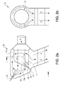
- Fig. 2a shows a second embodiment of an exhaust gas aftertreatment device 1b according to the present invention.
- One feature of the embodiment of the invention shown in fig. 2a that is configured differently than for the embodiment disclosed in fig. 1a and 1b is the outlet surface 12b of the first catalytic substrate 8.
- the outlet surface 12a of the embodiment of fig. 1a is perpendicular to said first flow direction A through said first catalytic substrate 8 whereas the outlet surface 12b of the embodiment of fig. 1b is inclined in an angle c which is less than 90 degrees.
- the configuration of said outlet surface 12b enables that a larger surface area of said outlet surface 12b is facing the reductant injector 10. Corresponding to what previously has been described in relation to fig.
- 1a and 1b reductant is injected, by spraying, into the exhaust gas flow by a reductant injector 10.
- the configuration of said outlet surface 12b increases the distance between the reductant injector 10 and the outlet surface 12b, which will prolong the time and distance for reductant evaporation and mixing. If unevaporated reductant still reaches the outlet surface 12b the configuration of the outlet surface 12b enables that unevaporated reductant is more evenly distributed over the outlet surface 12b.
- the evaporation of the unevaporated reductant reaching the outlet surface 12b of the first catalytic substrate 8 is promoted by that the first catalytic substrate 8 is heated by the hot exhaust gas flow.
- the configuration of the outlet surface 12b is beneficial from an reductant evaporation standpoint both due to the prolonged distance for mixing and evaporation and due to the larger surface facing the reductant injector.
- the exhaust gas aftertreatment device 1b of the exemplary aspect of the present invention shown in fig. 2a additionally comprises guiding means 17.
- the guiding means 17 is arranged such that the guiding means 17 seals against the redirecting wall 11, at a position adjacent to said second end 14, and at a rear edge 20, provided adjacent to said outlet surface 12b of the outer circumference 15 of the first catalytic substrate 8.
- the guiding means 17 provide that at least a portion of the exhaust gas flow after passing said first catalytic substrate 8 is forced to said redirecting wall 11 where it will be redirected to pass said outer circumference 15 of the first catalytic substrate 8.
- Said arrangement comprising guiding means 17 may improve the mixing of exhaust gas flow and injected reductant and can be used to secure that no exhaust gas flow can flow directly from said first catalytic substrate 8 to said second catalytic substrate 9, without at least passing a small portion of the outer circumference 15.
- an angle c between the first main flow direction A of the first catalytic substrate 8 and a third main flow direction C of the second catalytic substrate 9 is less than 90 degrees.
- said angle is less than 90 degrees, as well as aspects where said angle is more than 90 degrees, may be advantageous for different vehicle designs with different packaging requirements.
- Fig. 2b discloses a cross sectional view of the exemplary aspect of the exhaust gas aftertreatment device 1b of the present invention disclosed in fig. 2a.
- Fig. 2b shows the same features as fig. 1b with the exception that the guiding means 17 of the aspect of the invention shown in fig. 2a is shown.
Landscapes
- Engineering & Computer Science (AREA)
- Chemical & Material Sciences (AREA)
- Chemical Kinetics & Catalysis (AREA)
- Combustion & Propulsion (AREA)
- General Engineering & Computer Science (AREA)
- Mechanical Engineering (AREA)
- Health & Medical Sciences (AREA)
- Toxicology (AREA)
- Materials Engineering (AREA)
- General Chemical & Material Sciences (AREA)
- Oil, Petroleum & Natural Gas (AREA)
- Analytical Chemistry (AREA)
- Environmental & Geological Engineering (AREA)
- Biomedical Technology (AREA)
- Exhaust Gas After Treatment (AREA)
Priority Applications (3)
| Application Number | Priority Date | Filing Date | Title |
|---|---|---|---|
| EP14174777.4A EP2960456B1 (fr) | 2014-06-27 | 2014-06-27 | dispositif de traitement de gaz d'echappement compact et angulair |
| CN201510579817.3A CN105221223B (zh) | 2014-06-27 | 2015-06-19 | 用于内燃发动机的排气后处理装置及具有该装置的车辆 |
| US14/746,397 US10012124B2 (en) | 2014-06-27 | 2015-06-22 | Angled and compact exhaust gas aftertreatment device |
Applications Claiming Priority (1)
| Application Number | Priority Date | Filing Date | Title |
|---|---|---|---|
| EP14174777.4A EP2960456B1 (fr) | 2014-06-27 | 2014-06-27 | dispositif de traitement de gaz d'echappement compact et angulair |
Publications (2)
| Publication Number | Publication Date |
|---|---|
| EP2960456A1 true EP2960456A1 (fr) | 2015-12-30 |
| EP2960456B1 EP2960456B1 (fr) | 2017-04-12 |
Family
ID=51133854
Family Applications (1)
| Application Number | Title | Priority Date | Filing Date |
|---|---|---|---|
| EP14174777.4A Active EP2960456B1 (fr) | 2014-06-27 | 2014-06-27 | dispositif de traitement de gaz d'echappement compact et angulair |
Country Status (3)
| Country | Link |
|---|---|
| US (1) | US10012124B2 (fr) |
| EP (1) | EP2960456B1 (fr) |
| CN (1) | CN105221223B (fr) |
Cited By (5)
| Publication number | Priority date | Publication date | Assignee | Title |
|---|---|---|---|---|
| DE102016114283A1 (de) * | 2016-08-02 | 2018-02-08 | Benteler Automobiltechnik Gmbh | Abgasnachbehandlungsanordnung |
| EP3311013A1 (fr) * | 2015-06-17 | 2018-04-25 | Renault S.A.S. | Systeme de depollution des gaz d'echappement optimise |
| FR3061517A1 (fr) * | 2017-01-04 | 2018-07-06 | Peugeot Citroen Automobiles Sa | Organe de traitement de gaz a corps de traitement de gaz en biseau |
| EP3505732A4 (fr) * | 2016-12-16 | 2019-07-03 | Mazda Motor Corporation | Dispositif d'échappement de moteur |
| EP3674523A1 (fr) * | 2018-12-27 | 2020-07-01 | Volkswagen Ag | Système de traitement des gaz d'échappement pour un moteur à combustion interne |
Families Citing this family (9)
| Publication number | Priority date | Publication date | Assignee | Title |
|---|---|---|---|---|
| US9616383B2 (en) * | 2014-02-06 | 2017-04-11 | Johnson Matthey Catalysts (Germany) Gmbh | Compact selective catalytic reduction system for nitrogen oxide reduction in the oxygen-rich exhaust of 500 to 4500 kW internal combustion engines |
| DE102015201193B3 (de) * | 2015-01-23 | 2016-06-30 | Continental Automotive Gmbh | Abgasreinigungskomponente zur Reinigung der Abgase einer Verbrennungskraftmaschine |
| DE102016122769A1 (de) * | 2016-11-25 | 2018-05-30 | Eberspächer Exhaust Technology GmbH & Co. KG | Abgasbehandlungsanordnung |
| WO2018149509A1 (fr) | 2017-02-20 | 2018-08-23 | Volvo Penta Corporation | Boîte de mélange, son utilisation et procédé de mélange |
| US11473466B2 (en) * | 2019-01-09 | 2022-10-18 | Marelli Corporation | Exhaust gas processing device |
| CN113906199B (zh) * | 2019-05-22 | 2023-11-28 | 日产自动车株式会社 | 催化转化器 |
| DE102019208825A1 (de) * | 2019-06-18 | 2020-12-24 | Robert Bosch Gmbh | Abgasstrang zur Abgasnachbehandlung |
| DE102022104314A1 (de) * | 2022-02-23 | 2023-08-24 | Friedrich Boysen GmbH & Co KG. | Vorrichtung zum Vermischen eines Zusatzstoffes mit einem Gasstrom |
| CN114961941B (zh) * | 2022-05-23 | 2023-07-14 | 一汽解放汽车有限公司 | 尾气处理装置及车辆 |
Citations (3)
| Publication number | Priority date | Publication date | Assignee | Title |
|---|---|---|---|---|
| WO2001042630A2 (fr) * | 1999-12-09 | 2001-06-14 | Eminox Limited | Dispositif |
| US20080041036A1 (en) | 2006-08-16 | 2008-02-21 | Emitec Gesellschaft Fur Emissionstechnologie Mbh | Method for Adding at Least One Reactant to an Exhaust Gas Stream and Device for Treating an Exhaust Gas Stream of an Internal Combustion Engine |
| DE102010034705A1 (de) * | 2010-08-18 | 2012-02-23 | Emitec Gesellschaft Für Emissionstechnologie Mbh | Kompakte Abgasbehandlungseinheit mit Reaktionsmittelzugabe |
Family Cites Families (3)
| Publication number | Priority date | Publication date | Assignee | Title |
|---|---|---|---|---|
| JP2006515401A (ja) * | 2003-01-14 | 2006-05-25 | エミテック ゲゼルシヤフト フユア エミツシオンス テクノロギー ミツト ベシユレンクテル ハフツング | 入れ子式に位置する往流領域及び還流領域を備え同じ側で排ガスの流出入を行う省スペース形排ガス後処理装置 |
| US8015802B2 (en) * | 2004-11-25 | 2011-09-13 | Komatsu Ltd. | Exhaust gas purification device for internal combustion engine |
| EP2917522B1 (fr) * | 2012-11-07 | 2018-09-26 | Johnson Matthey Public Limited Company | Système d'échappement |
-
2014
- 2014-06-27 EP EP14174777.4A patent/EP2960456B1/fr active Active
-
2015
- 2015-06-19 CN CN201510579817.3A patent/CN105221223B/zh active Active
- 2015-06-22 US US14/746,397 patent/US10012124B2/en active Active
Patent Citations (3)
| Publication number | Priority date | Publication date | Assignee | Title |
|---|---|---|---|---|
| WO2001042630A2 (fr) * | 1999-12-09 | 2001-06-14 | Eminox Limited | Dispositif |
| US20080041036A1 (en) | 2006-08-16 | 2008-02-21 | Emitec Gesellschaft Fur Emissionstechnologie Mbh | Method for Adding at Least One Reactant to an Exhaust Gas Stream and Device for Treating an Exhaust Gas Stream of an Internal Combustion Engine |
| DE102010034705A1 (de) * | 2010-08-18 | 2012-02-23 | Emitec Gesellschaft Für Emissionstechnologie Mbh | Kompakte Abgasbehandlungseinheit mit Reaktionsmittelzugabe |
Cited By (7)
| Publication number | Priority date | Publication date | Assignee | Title |
|---|---|---|---|---|
| EP3311013A1 (fr) * | 2015-06-17 | 2018-04-25 | Renault S.A.S. | Systeme de depollution des gaz d'echappement optimise |
| DE102016114283A1 (de) * | 2016-08-02 | 2018-02-08 | Benteler Automobiltechnik Gmbh | Abgasnachbehandlungsanordnung |
| EP3505732A4 (fr) * | 2016-12-16 | 2019-07-03 | Mazda Motor Corporation | Dispositif d'échappement de moteur |
| FR3061517A1 (fr) * | 2017-01-04 | 2018-07-06 | Peugeot Citroen Automobiles Sa | Organe de traitement de gaz a corps de traitement de gaz en biseau |
| EP3674523A1 (fr) * | 2018-12-27 | 2020-07-01 | Volkswagen Ag | Système de traitement des gaz d'échappement pour un moteur à combustion interne |
| CN111379612A (zh) * | 2018-12-27 | 2020-07-07 | 大众汽车有限公司 | 用于内燃机的废气再处理系统 |
| US11098633B2 (en) | 2018-12-27 | 2021-08-24 | Volkswagen Aktiengesellschaft | Exhaust gas aftertreatment system for an internal combustion engine |
Also Published As
| Publication number | Publication date |
|---|---|
| CN105221223A (zh) | 2016-01-06 |
| US20150377110A1 (en) | 2015-12-31 |
| CN105221223B (zh) | 2019-07-02 |
| US10012124B2 (en) | 2018-07-03 |
| EP2960456B1 (fr) | 2017-04-12 |
Similar Documents
| Publication | Publication Date | Title |
|---|---|---|
| EP2960456B1 (fr) | dispositif de traitement de gaz d'echappement compact et angulair | |
| US10188994B2 (en) | Method, apparatus and system for aftertreatment of exhaust gas | |
| US11465108B2 (en) | Dosing and mixing arrangement for use in exhaust aftertreatment | |
| KR101914396B1 (ko) | 혼합기 조립체를 위한 절연 커버 | |
| US9057312B2 (en) | System and apparatus for reducing reductant deposit formation in exhaust aftertreatment systems | |
| US8997463B2 (en) | Reductant delivery unit for automotive selective catalytic reduction with reducing agent heating | |
| KR102342002B1 (ko) | 자동차의 배기가스 후처리 시스템용 믹서 장치, 배기가스 후처리 시스템 및 자동차 | |
| US20080155973A1 (en) | Exhaust emission control device with additive injector | |
| US9376951B2 (en) | Exhaust gas aftertreatment device | |
| US20110274590A1 (en) | Inverted Exhaust Gas Treatment Injector | |
| US10371032B2 (en) | Exhaust gas purifier for engine | |
| JP6625143B2 (ja) | 自動車の内燃機関用の排気ガス後処理装置 | |
| EP3379046B1 (fr) | Système de post-traitement de gaz d'échappement | |
| US20150361842A1 (en) | Exhaust system for a vehicle | |
| CN109563759B (zh) | 还原剂配量单元的紧凑侧面喂给进入端口 | |
| US10632838B2 (en) | Leveling nipple for tank capable of preventing spit-back | |
| KR102324758B1 (ko) | 차량용 도징모듈 | |
| KR20170016067A (ko) | 질소산화물 저감장치 및 그 제어시스템 |
Legal Events
| Date | Code | Title | Description |
|---|---|---|---|
| PUAI | Public reference made under article 153(3) epc to a published international application that has entered the european phase |
Free format text: ORIGINAL CODE: 0009012 |
|
| AK | Designated contracting states |
Kind code of ref document: A1 Designated state(s): AL AT BE BG CH CY CZ DE DK EE ES FI FR GB GR HR HU IE IS IT LI LT LU LV MC MK MT NL NO PL PT RO RS SE SI SK SM TR |
|
| AX | Request for extension of the european patent |
Extension state: BA ME |
|
| 17P | Request for examination filed |
Effective date: 20160630 |
|
| RBV | Designated contracting states (corrected) |
Designated state(s): AL AT BE BG CH CY CZ DE DK EE ES FI FR GB GR HR HU IE IS IT LI LT LU LV MC MK MT NL NO PL PT RO RS SE SI SK SM TR |
|
| REG | Reference to a national code |
Ref country code: DE Ref legal event code: R079 Ref document number: 602014008460 Country of ref document: DE Free format text: PREVIOUS MAIN CLASS: F01N0003200000 Ipc: F01N0013000000 |
|
| RIC1 | Information provided on ipc code assigned before grant |
Ipc: F01N 3/28 20060101ALI20160921BHEP Ipc: F01N 3/20 20060101ALI20160921BHEP Ipc: F01N 3/10 20060101ALI20160921BHEP Ipc: F01N 13/00 20100101AFI20160921BHEP Ipc: B01D 53/94 20060101ALI20160921BHEP |
|
| GRAP | Despatch of communication of intention to grant a patent |
Free format text: ORIGINAL CODE: EPIDOSNIGR1 |
|
| INTG | Intention to grant announced |
Effective date: 20161109 |
|
| GRAS | Grant fee paid |
Free format text: ORIGINAL CODE: EPIDOSNIGR3 |
|
| GRAA | (expected) grant |
Free format text: ORIGINAL CODE: 0009210 |
|
| AK | Designated contracting states |
Kind code of ref document: B1 Designated state(s): AL AT BE BG CH CY CZ DE DK EE ES FI FR GB GR HR HU IE IS IT LI LT LU LV MC MK MT NL NO PL PT RO RS SE SI SK SM TR |
|
| REG | Reference to a national code |
Ref country code: GB Ref legal event code: FG4D |
|
| REG | Reference to a national code |
Ref country code: CH Ref legal event code: EP |
|
| REG | Reference to a national code |
Ref country code: IE Ref legal event code: FG4D |
|
| REG | Reference to a national code |
Ref country code: AT Ref legal event code: REF Ref document number: 884131 Country of ref document: AT Kind code of ref document: T Effective date: 20170515 |
|
| REG | Reference to a national code |
Ref country code: DE Ref legal event code: R096 Ref document number: 602014008460 Country of ref document: DE |
|
| REG | Reference to a national code |
Ref country code: SE Ref legal event code: TRGR |
|
| REG | Reference to a national code |
Ref country code: NL Ref legal event code: MP Effective date: 20170412 |
|
| REG | Reference to a national code |
Ref country code: LT Ref legal event code: MG4D |
|
| REG | Reference to a national code |
Ref country code: AT Ref legal event code: MK05 Ref document number: 884131 Country of ref document: AT Kind code of ref document: T Effective date: 20170412 |
|
| PG25 | Lapsed in a contracting state [announced via postgrant information from national office to epo] |
Ref country code: NL Free format text: LAPSE BECAUSE OF FAILURE TO SUBMIT A TRANSLATION OF THE DESCRIPTION OR TO PAY THE FEE WITHIN THE PRESCRIBED TIME-LIMIT Effective date: 20170412 |
|
| PG25 | Lapsed in a contracting state [announced via postgrant information from national office to epo] |
Ref country code: LT Free format text: LAPSE BECAUSE OF FAILURE TO SUBMIT A TRANSLATION OF THE DESCRIPTION OR TO PAY THE FEE WITHIN THE PRESCRIBED TIME-LIMIT Effective date: 20170412 Ref country code: GR Free format text: LAPSE BECAUSE OF FAILURE TO SUBMIT A TRANSLATION OF THE DESCRIPTION OR TO PAY THE FEE WITHIN THE PRESCRIBED TIME-LIMIT Effective date: 20170713 Ref country code: AT Free format text: LAPSE BECAUSE OF FAILURE TO SUBMIT A TRANSLATION OF THE DESCRIPTION OR TO PAY THE FEE WITHIN THE PRESCRIBED TIME-LIMIT Effective date: 20170412 Ref country code: FI Free format text: LAPSE BECAUSE OF FAILURE TO SUBMIT A TRANSLATION OF THE DESCRIPTION OR TO PAY THE FEE WITHIN THE PRESCRIBED TIME-LIMIT Effective date: 20170412 Ref country code: HR Free format text: LAPSE BECAUSE OF FAILURE TO SUBMIT A TRANSLATION OF THE DESCRIPTION OR TO PAY THE FEE WITHIN THE PRESCRIBED TIME-LIMIT Effective date: 20170412 Ref country code: ES Free format text: LAPSE BECAUSE OF FAILURE TO SUBMIT A TRANSLATION OF THE DESCRIPTION OR TO PAY THE FEE WITHIN THE PRESCRIBED TIME-LIMIT Effective date: 20170412 Ref country code: NO Free format text: LAPSE BECAUSE OF FAILURE TO SUBMIT A TRANSLATION OF THE DESCRIPTION OR TO PAY THE FEE WITHIN THE PRESCRIBED TIME-LIMIT Effective date: 20170712 |
|
| PG25 | Lapsed in a contracting state [announced via postgrant information from national office to epo] |
Ref country code: LV Free format text: LAPSE BECAUSE OF FAILURE TO SUBMIT A TRANSLATION OF THE DESCRIPTION OR TO PAY THE FEE WITHIN THE PRESCRIBED TIME-LIMIT Effective date: 20170412 Ref country code: RS Free format text: LAPSE BECAUSE OF FAILURE TO SUBMIT A TRANSLATION OF THE DESCRIPTION OR TO PAY THE FEE WITHIN THE PRESCRIBED TIME-LIMIT Effective date: 20170412 Ref country code: IS Free format text: LAPSE BECAUSE OF FAILURE TO SUBMIT A TRANSLATION OF THE DESCRIPTION OR TO PAY THE FEE WITHIN THE PRESCRIBED TIME-LIMIT Effective date: 20170812 Ref country code: PL Free format text: LAPSE BECAUSE OF FAILURE TO SUBMIT A TRANSLATION OF THE DESCRIPTION OR TO PAY THE FEE WITHIN THE PRESCRIBED TIME-LIMIT Effective date: 20170412 Ref country code: BG Free format text: LAPSE BECAUSE OF FAILURE TO SUBMIT A TRANSLATION OF THE DESCRIPTION OR TO PAY THE FEE WITHIN THE PRESCRIBED TIME-LIMIT Effective date: 20170712 |
|
| REG | Reference to a national code |
Ref country code: DE Ref legal event code: R097 Ref document number: 602014008460 Country of ref document: DE |
|
| PG25 | Lapsed in a contracting state [announced via postgrant information from national office to epo] |
Ref country code: SK Free format text: LAPSE BECAUSE OF FAILURE TO SUBMIT A TRANSLATION OF THE DESCRIPTION OR TO PAY THE FEE WITHIN THE PRESCRIBED TIME-LIMIT Effective date: 20170412 Ref country code: CZ Free format text: LAPSE BECAUSE OF FAILURE TO SUBMIT A TRANSLATION OF THE DESCRIPTION OR TO PAY THE FEE WITHIN THE PRESCRIBED TIME-LIMIT Effective date: 20170412 Ref country code: MC Free format text: LAPSE BECAUSE OF FAILURE TO SUBMIT A TRANSLATION OF THE DESCRIPTION OR TO PAY THE FEE WITHIN THE PRESCRIBED TIME-LIMIT Effective date: 20170412 Ref country code: RO Free format text: LAPSE BECAUSE OF FAILURE TO SUBMIT A TRANSLATION OF THE DESCRIPTION OR TO PAY THE FEE WITHIN THE PRESCRIBED TIME-LIMIT Effective date: 20170412 Ref country code: EE Free format text: LAPSE BECAUSE OF FAILURE TO SUBMIT A TRANSLATION OF THE DESCRIPTION OR TO PAY THE FEE WITHIN THE PRESCRIBED TIME-LIMIT Effective date: 20170412 Ref country code: DK Free format text: LAPSE BECAUSE OF FAILURE TO SUBMIT A TRANSLATION OF THE DESCRIPTION OR TO PAY THE FEE WITHIN THE PRESCRIBED TIME-LIMIT Effective date: 20170412 |
|
| REG | Reference to a national code |
Ref country code: CH Ref legal event code: PL |
|
| PLBE | No opposition filed within time limit |
Free format text: ORIGINAL CODE: 0009261 |
|
| STAA | Information on the status of an ep patent application or granted ep patent |
Free format text: STATUS: NO OPPOSITION FILED WITHIN TIME LIMIT |
|
| PG25 | Lapsed in a contracting state [announced via postgrant information from national office to epo] |
Ref country code: IT Free format text: LAPSE BECAUSE OF FAILURE TO SUBMIT A TRANSLATION OF THE DESCRIPTION OR TO PAY THE FEE WITHIN THE PRESCRIBED TIME-LIMIT Effective date: 20170412 Ref country code: SM Free format text: LAPSE BECAUSE OF FAILURE TO SUBMIT A TRANSLATION OF THE DESCRIPTION OR TO PAY THE FEE WITHIN THE PRESCRIBED TIME-LIMIT Effective date: 20170412 |
|
| 26N | No opposition filed |
Effective date: 20180115 |
|
| REG | Reference to a national code |
Ref country code: FR Ref legal event code: ST Effective date: 20180228 |
|
| REG | Reference to a national code |
Ref country code: IE Ref legal event code: MM4A |
|
| PG25 | Lapsed in a contracting state [announced via postgrant information from national office to epo] |
Ref country code: IE Free format text: LAPSE BECAUSE OF NON-PAYMENT OF DUE FEES Effective date: 20170627 Ref country code: LU Free format text: LAPSE BECAUSE OF NON-PAYMENT OF DUE FEES Effective date: 20170627 Ref country code: LI Free format text: LAPSE BECAUSE OF NON-PAYMENT OF DUE FEES Effective date: 20170630 Ref country code: CH Free format text: LAPSE BECAUSE OF NON-PAYMENT OF DUE FEES Effective date: 20170630 |
|
| PG25 | Lapsed in a contracting state [announced via postgrant information from national office to epo] |
Ref country code: FR Free format text: LAPSE BECAUSE OF NON-PAYMENT OF DUE FEES Effective date: 20170630 Ref country code: SI Free format text: LAPSE BECAUSE OF FAILURE TO SUBMIT A TRANSLATION OF THE DESCRIPTION OR TO PAY THE FEE WITHIN THE PRESCRIBED TIME-LIMIT Effective date: 20170412 |
|
| REG | Reference to a national code |
Ref country code: BE Ref legal event code: MM Effective date: 20170630 |
|
| PG25 | Lapsed in a contracting state [announced via postgrant information from national office to epo] |
Ref country code: BE Free format text: LAPSE BECAUSE OF NON-PAYMENT OF DUE FEES Effective date: 20170630 |
|
| PG25 | Lapsed in a contracting state [announced via postgrant information from national office to epo] |
Ref country code: MT Free format text: LAPSE BECAUSE OF NON-PAYMENT OF DUE FEES Effective date: 20170627 |
|
| PG25 | Lapsed in a contracting state [announced via postgrant information from national office to epo] |
Ref country code: HU Free format text: LAPSE BECAUSE OF FAILURE TO SUBMIT A TRANSLATION OF THE DESCRIPTION OR TO PAY THE FEE WITHIN THE PRESCRIBED TIME-LIMIT; INVALID AB INITIO Effective date: 20140627 |
|
| PGFP | Annual fee paid to national office [announced via postgrant information from national office to epo] |
Ref country code: SE Payment date: 20190620 Year of fee payment: 6 |
|
| PG25 | Lapsed in a contracting state [announced via postgrant information from national office to epo] |
Ref country code: CY Free format text: LAPSE BECAUSE OF FAILURE TO SUBMIT A TRANSLATION OF THE DESCRIPTION OR TO PAY THE FEE WITHIN THE PRESCRIBED TIME-LIMIT Effective date: 20170412 |
|
| PGFP | Annual fee paid to national office [announced via postgrant information from national office to epo] |
Ref country code: GB Payment date: 20190613 Year of fee payment: 6 |
|
| PG25 | Lapsed in a contracting state [announced via postgrant information from national office to epo] |
Ref country code: MK Free format text: LAPSE BECAUSE OF FAILURE TO SUBMIT A TRANSLATION OF THE DESCRIPTION OR TO PAY THE FEE WITHIN THE PRESCRIBED TIME-LIMIT Effective date: 20170412 |
|
| PG25 | Lapsed in a contracting state [announced via postgrant information from national office to epo] |
Ref country code: TR Free format text: LAPSE BECAUSE OF FAILURE TO SUBMIT A TRANSLATION OF THE DESCRIPTION OR TO PAY THE FEE WITHIN THE PRESCRIBED TIME-LIMIT Effective date: 20170412 |
|
| PG25 | Lapsed in a contracting state [announced via postgrant information from national office to epo] |
Ref country code: PT Free format text: LAPSE BECAUSE OF FAILURE TO SUBMIT A TRANSLATION OF THE DESCRIPTION OR TO PAY THE FEE WITHIN THE PRESCRIBED TIME-LIMIT Effective date: 20170412 |
|
| PG25 | Lapsed in a contracting state [announced via postgrant information from national office to epo] |
Ref country code: AL Free format text: LAPSE BECAUSE OF FAILURE TO SUBMIT A TRANSLATION OF THE DESCRIPTION OR TO PAY THE FEE WITHIN THE PRESCRIBED TIME-LIMIT Effective date: 20170412 |
|
| GBPC | Gb: european patent ceased through non-payment of renewal fee |
Effective date: 20200627 |
|
| PG25 | Lapsed in a contracting state [announced via postgrant information from national office to epo] |
Ref country code: GB Free format text: LAPSE BECAUSE OF NON-PAYMENT OF DUE FEES Effective date: 20200627 |
|
| PG25 | Lapsed in a contracting state [announced via postgrant information from national office to epo] |
Ref country code: SE Free format text: LAPSE BECAUSE OF NON-PAYMENT OF DUE FEES Effective date: 20200628 |
|
| REG | Reference to a national code |
Ref country code: SE Ref legal event code: EUG |
|
| P01 | Opt-out of the competence of the unified patent court (upc) registered |
Effective date: 20231212 |
|
| PGFP | Annual fee paid to national office [announced via postgrant information from national office to epo] |
Ref country code: DE Payment date: 20250520 Year of fee payment: 12 |