EP2960493B1 - Système de fixation pour câble, en particulier pour des éoliennes - Google Patents
Système de fixation pour câble, en particulier pour des éoliennes Download PDFInfo
- Publication number
- EP2960493B1 EP2960493B1 EP15002073.3A EP15002073A EP2960493B1 EP 2960493 B1 EP2960493 B1 EP 2960493B1 EP 15002073 A EP15002073 A EP 15002073A EP 2960493 B1 EP2960493 B1 EP 2960493B1
- Authority
- EP
- European Patent Office
- Prior art keywords
- cable
- band
- fastening system
- cable holders
- cables
- Prior art date
- Legal status (The legal status is an assumption and is not a legal conclusion. Google has not performed a legal analysis and makes no representation as to the accuracy of the status listed.)
- Active
Links
Images


Classifications
-
- F—MECHANICAL ENGINEERING; LIGHTING; HEATING; WEAPONS; BLASTING
- F03—MACHINES OR ENGINES FOR LIQUIDS; WIND, SPRING, OR WEIGHT MOTORS; PRODUCING MECHANICAL POWER OR A REACTIVE PROPULSIVE THRUST, NOT OTHERWISE PROVIDED FOR
- F03D—WIND MOTORS
- F03D80/00—Details, components or accessories not provided for in groups F03D1/00 - F03D17/00
- F03D80/80—Arrangement of components within nacelles or towers
- F03D80/82—Arrangement of components within nacelles or towers of electrical components
- F03D80/85—Cabling
-
- F—MECHANICAL ENGINEERING; LIGHTING; HEATING; WEAPONS; BLASTING
- F16—ENGINEERING ELEMENTS AND UNITS; GENERAL MEASURES FOR PRODUCING AND MAINTAINING EFFECTIVE FUNCTIONING OF MACHINES OR INSTALLATIONS; THERMAL INSULATION IN GENERAL
- F16L—PIPES; JOINTS OR FITTINGS FOR PIPES; SUPPORTS FOR PIPES, CABLES OR PROTECTIVE TUBING; MEANS FOR THERMAL INSULATION IN GENERAL
- F16L3/00—Supports for pipes, cables or protective tubing, e.g. hangers, holders, clamps, cleats, clips, brackets
- F16L3/22—Supports for pipes, cables or protective tubing, e.g. hangers, holders, clamps, cleats, clips, brackets specially adapted for supporting a number of parallel pipes at intervals
- F16L3/223—Supports for pipes, cables or protective tubing, e.g. hangers, holders, clamps, cleats, clips, brackets specially adapted for supporting a number of parallel pipes at intervals each support having one transverse base for supporting the pipes
- F16L3/227—Supports for pipes, cables or protective tubing, e.g. hangers, holders, clamps, cleats, clips, brackets specially adapted for supporting a number of parallel pipes at intervals each support having one transverse base for supporting the pipes each pipe being supported by a separate element fastened to the base
-
- B—PERFORMING OPERATIONS; TRANSPORTING
- B66—HOISTING; LIFTING; HAULING
- B66D—CAPSTANS; WINCHES; TACKLES, e.g. PULLEY BLOCKS; HOISTS
- B66D1/00—Rope, cable, or chain winding mechanisms; Capstans
- B66D1/28—Other constructional details
- B66D1/36—Guiding, or otherwise ensuring winding in an orderly manner, of ropes, cables, or chains
-
- F—MECHANICAL ENGINEERING; LIGHTING; HEATING; WEAPONS; BLASTING
- F16—ENGINEERING ELEMENTS AND UNITS; GENERAL MEASURES FOR PRODUCING AND MAINTAINING EFFECTIVE FUNCTIONING OF MACHINES OR INSTALLATIONS; THERMAL INSULATION IN GENERAL
- F16L—PIPES; JOINTS OR FITTINGS FOR PIPES; SUPPORTS FOR PIPES, CABLES OR PROTECTIVE TUBING; MEANS FOR THERMAL INSULATION IN GENERAL
- F16L3/00—Supports for pipes, cables or protective tubing, e.g. hangers, holders, clamps, cleats, clips, brackets
- F16L3/08—Supports for pipes, cables or protective tubing, e.g. hangers, holders, clamps, cleats, clips, brackets substantially surrounding the pipe, cable or protective tubing
- F16L3/10—Supports for pipes, cables or protective tubing, e.g. hangers, holders, clamps, cleats, clips, brackets substantially surrounding the pipe, cable or protective tubing divided, i.e. with two members engaging the pipe, cable or protective tubing
-
- H—ELECTRICITY
- H02—GENERATION; CONVERSION OR DISTRIBUTION OF ELECTRIC POWER
- H02G—INSTALLATION OF ELECTRIC CABLES OR LINES, OR OF COMBINED OPTICAL AND ELECTRIC CABLES OR LINES
- H02G3/00—Installations of electric cables or lines or protective tubing therefor in or on buildings, equivalent structures or vehicles
- H02G3/30—Installations of cables or lines on walls, floors or ceilings
- H02G3/32—Installations of cables or lines on walls, floors or ceilings using mounting clamps
-
- F—MECHANICAL ENGINEERING; LIGHTING; HEATING; WEAPONS; BLASTING
- F05—INDEXING SCHEMES RELATING TO ENGINES OR PUMPS IN VARIOUS SUBCLASSES OF CLASSES F01-F04
- F05B—INDEXING SCHEME RELATING TO WIND, SPRING, WEIGHT, INERTIA OR LIKE MOTORS, TO MACHINES OR ENGINES FOR LIQUIDS COVERED BY SUBCLASSES F03B, F03D AND F03G
- F05B2250/00—Geometry
- F05B2250/10—Geometry two-dimensional
- F05B2250/14—Geometry two-dimensional elliptical
- F05B2250/141—Geometry two-dimensional elliptical circular
-
- Y—GENERAL TAGGING OF NEW TECHNOLOGICAL DEVELOPMENTS; GENERAL TAGGING OF CROSS-SECTIONAL TECHNOLOGIES SPANNING OVER SEVERAL SECTIONS OF THE IPC; TECHNICAL SUBJECTS COVERED BY FORMER USPC CROSS-REFERENCE ART COLLECTIONS [XRACs] AND DIGESTS
- Y02—TECHNOLOGIES OR APPLICATIONS FOR MITIGATION OR ADAPTATION AGAINST CLIMATE CHANGE
- Y02E—REDUCTION OF GREENHOUSE GAS [GHG] EMISSIONS, RELATED TO ENERGY GENERATION, TRANSMISSION OR DISTRIBUTION
- Y02E10/00—Energy generation through renewable energy sources
- Y02E10/70—Wind energy
- Y02E10/72—Wind turbines with rotation axis in wind direction
Definitions
- the invention relates to a fastening system for cables, in particular in wind power plants, having the features in the preamble of claim 1.
- the cables To prevent the cables from rubbing against each other during rotary movements, the cables must be kept at a distance.
- the cables are held over a round support structure for this purpose, for example in the form of a piece of pipe to which the Distributed cable and attached to it with simple clamps. Such assembly is complicated and cumbersome.
- the US 2009/0309313 A1 describes a fastening system for cables with a base body which can be fixed to a support structure, and with cable receptacles, which have an opening for inserting cables, which can be closed by a covering device, wherein the cable receptacles provided in the form of attachable to the main body components and the main body are arranged in an at least over a part of a ring extending arrangement with an external opening and wherein the covering device has holding body, by means of which the opening of the respective cable receptacle for fixing inserted cables can be blocked.
- the invention has for its object to provide a particularly suitable for the application in question fastening system.
- a significant feature of the invention is that the holding body each having a cover member which is hinged to the cable receptacle and having a slidably guided clamping member which exerts a holding force by a spring arrangement in the direction of the male cable, that the cover part at its Top forms a support surface for the strap and / or that the holding body defined by a locking or other fixing connection in a cable receptacles closing or blocking position are held. Due to the pivotable mounting of the holding body to the cable holder, the holding body are captively secured to the respective cable receptacle and need not be specially handled for the assembly process.
- the cables can also be positioned in a cable loop suspended from the machine house in the tower and spaced from each other, as in the tower segments themselves, so that scrubbing of cables is avoided in any case.
- further cable receptacles are provided in the form of attachable to the body components, opens up the advantageous possibility to realize with little design effort and cost, a fastening system that is particularly high load capacity.
- different materials can be used for this and the body.
- cable receptacles can be press-formed from a plastic material in a rational and cost-effective manner, while the basic body is designed as a metal construction, for example in the form of a steel construction of high structural strength, i. can be designed for optimum strength, without the need to dispense with the use of existing low-cost material cable recordings.
- the covering holding body are present, by means of which the insertion is blocked for prefixing inserted into the cable ducts of the cable receptacles cables, the cable, since they are secured against falling out, can insert one after the other comfortably in the cable bushings.
- the covering further comprises a clamping band which exerts the holding force on the cables via the holding body, only a single screwing operation for clamping the clamping band is required to secure the entire number of the cables held in ring arrangement. If necessary, a holding force can also be exerted on the accommodated cables via the covering device.
- the base body comprises a band of steel, which extends between end portions forming attachment points for anchoring to the support structure in a preferably forming part of a circular arc forming along which a series of cable receptacles.
- a steel substructure ensures a secure anchoring of the cables, even if the cable supports made of a material of lesser strength, such as plastic.
- a particularly high strength of the overall construction can be achieved in embodiments in which a traverse extending in the form of a chord through the interior of the sheet is provided, the band of the sheet on both sides between the serving as anchoring point end portions and the respective end of the series Penetrates cable receptacles and protrudes outwards, wherein the protruding ends of the traverse each form a point of attack for the strap.
- a traverse especially if it is welded to the penetration points of the strip with this, forms a particularly effective reinforcement of the example, semicircular arc, so that high strength is ensured with little material cost.
- the clamping force can be initiated with predominantly extending in the tape longitudinal direction force component and therefore with high reliability in the construction.
- the traverse is formed in particularly preferred embodiments by a steel rod having a cross-section in the form of a rectangle and extends through with extending in the circumferential direction of the arc long sides a slot in the band of the arc.
- the clamping force of the clamping band acts in the direction of the long sides of the rectangular profile, ie in the direction of the larger bending resistance of the traverse.
- each cable receptacle is individually connectable to the band of the body and each has a trough-like cable gland.
- the arrangement can be made so that the cable receptacles to rest on the band have a curvature corresponding vaulted base surface, between the latter and the tape a cable receptacles on the base body locking locking is formed.
- Such a system is characterized by a particularly low installation costs.
- the precise alignment of the cable receptacles on the collar can be accomplished particularly easily if the cable receptacles are arranged between positioning bodies which extend radially from the arcuate band in a row arrangement running in the circumferential direction of the band and engage with guide channels which pass through recesses in the side walls the cable receptacles are formed.
- the positioning also serve to accommodate acting between cable and body shots forces.
- the Fig. 1 shows in a separate representation of the main body 1 of an embodiment to be described without attached cable recordings.
- the main body 1 is a steel construction of a steel strip 3, which is semicircularly bent between end sections 5.
- At the end portions 5 are angled lugs 7 with slots 9 for anchoring the body 1 to a support structure.
- the tabs 7 are angled in adaptation to the rounding of the tower wall relative to the end portions 5.
- the extending between the end portions 5 arc of the band 3 forms in the present example, the storage for eight cable receptacles that in Fig. 1 for the clarity of the representation of the body 1 not shown, but in the Fig. 2 to 5 are visible where the cable receptacles are labeled 11.
- the band 3 For the attachment of the cable receptacles 11 on the band 3 of the base body 1, the band 3 over the arc evenly distributed for each to be attached Cable receptacle 11 on a mounting hole 13 which is used for locking with the cable receptacle 11 by a snap connection with a latching dome 15 (FIG. Fig. 4 and 5 ) formed from the base 17 ( Fig. 5 ) of the respective cable receptacle 11 protrudes.
- the base 17 has a curvature, which is adapted to the circular arc of the band 3.
- the Fig. 4 shows the formed snap connection.
- FIG. 2 and 3 show the cable receptacles 11, when they are attached to the band 3, with their side surfaces 19 (FIG. Fig. 5 ) flush with each other, so that the cable receptacles 11 on the base body 1 form an arcuate series without interruption.
- FIG. 5 shows are in the side surfaces 19 of the cable receptacles 11 from the base 17 to the upper end through recesses 21 which are shaped so that in flush juxtaposition of the side surfaces 19 of two successive cable receptacles 11 in the recesses 21 positioning body are accommodated.
- These are cylindrical bolts 23 which are inserted into bolt holes 25 (FIG. Fig.
- the recesses 21 in the cable receptacles 11 have an inner, the bolt 23 adapted partial cylinder surface 25.
- the positioning bodies could also have a different cross-sectional shape.
- Fig. 1 shows, extends through the arc of the belt 3 in the manner of a bowstring a traverse 31, which is formed by a steel rod of rectangular cross-section.
- This traverse 31 penetrates slots 33 of the band 3 and projects with its end portions 35 in the radial direction, relative to the circular arc of the band 3 to the outside.
- this each forms an anchoring point 37 for a respective end of the tension band 39, which surrounds the row of cable receptacles 11, see Fig.
- the cross member 31 is a steel rod with a rectangular cross section and is in such an orientation through the slots 33 of the Bandes 3 out that the long sides of the rectangular profile in the circumferential direction of the belt 3 and have the traverse 31 thus opposes the force acting in the circumferential direction tensile force of the clamping band 39, the higher bending resistance.
- cable receivers 11 replace the two end portions 35 of the crossmember 31 respectively the outer positioning of the last cable holder 23 23 adapted the rectangular shape of these end portions 35, located in the respective recess 21 of the side surface 19 of Cable receptacles 11 at the bottom of the recess 21 a subsequent to the part cylinder surface 25, further recessed groove 41 (FIGS. Fig. 5 ), in which the end portion 35 of the crossbar 31 fits fitting.
- the clamping band 39 which by means of a prior art turnbuckle 43 ( Fig. 3 ) is on the top of holding bodies 45 at.
- the cable receptacles 11 each have a trough-like cable bushing 47, which tapers towards the trough base and at the upper end has an insertion opening for inserting the (not shown) cable.
- the holding body 45 have below an upper cover part, which forms the contact surface for the clamping band 39 on its upper side, a lower clamping part 51, which in the in Fig. 2 and 3 shown operating state via the insertion opening of the respective grommet 47 extends a force exerted on the inserted cable.
- the holding body 45 have on one side of their cover part 49 joint cheeks 53, with which they are hingedly hinged to a pivot bearing 55, which is located on the cable receptacles 11 at the insertion opening. Opposite the in Fig. 2 and 3 shown position, the holding body 45 are therefore pivoted away in an insertion position upwards to insert cables into the cable glands 47, before the clamping band 39 is applied, closed and tensioned. After performing the insertion process on the respective cable holder 11 of the holding body 45th pivoted from the loading position in a Vorfixierposition to the cable receptacle 47. In this Vorfixierposition the holding body 45 each by means of resilient locking tongues 57 are secured, which are formed on the cover member 49 on the joint cheeks 53 opposite end.
- the Fig. 6 illustrates a variant for the holding body 45.
- the holding body 45 as in Fig. 6 shown, a relative to the cover member 49 movable clamping member 51 have.
- the clamping part 51 has the shape of a rectangular plate, from the corner regions of which guide strips 63 extend in the direction of the cover part 49 and are guided in guide tracks 65 in the cover part 49 slidably.
- a spring assembly of a plurality of compression springs 67 is inserted, which delivers the clamping member 51 in the direction of the cable for their positioning.
- stop tabs 69 and 71 are provided on the guide 65 of the cover member 49 and on the guide rails 63 of the clamping member.
- the base body 1 forming steel construction, the cable holders 11, the holding body 45 and the positioning pins 23 can be made of cost-effective, rational production enabling materials, for example, be molded from plastic.
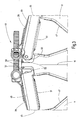
- the Fig. 7 shows in a separate representation of the main body of a modified embodiment.
- an alignment device is provided on the main body 1. This is intended in particular for purposes in which the base body 1 is to be mounted in a wind turbine on the inner wall of a conically shaped tower segment, which reduces toward the machine house in diameter, so that the inner wall has a skew to the vertical.
- the orientation of the plane of the sheet 3 with the cable receptacles 11 can be aligned in an orientation adapted to the respective wall inclination.
- the alignment device has for this purpose on the end portions 5 of the band 3 in each case the same direction cantilevered arm 71, at the end of each a threaded sleeve 73 is located.
Landscapes
- Engineering & Computer Science (AREA)
- General Engineering & Computer Science (AREA)
- Mechanical Engineering (AREA)
- Architecture (AREA)
- Civil Engineering (AREA)
- Structural Engineering (AREA)
- Life Sciences & Earth Sciences (AREA)
- Sustainable Development (AREA)
- Sustainable Energy (AREA)
- Chemical & Material Sciences (AREA)
- Combustion & Propulsion (AREA)
- Clamps And Clips (AREA)
- Wind Motors (AREA)
- Installation Of Indoor Wiring (AREA)
- Bridges Or Land Bridges (AREA)
Claims (9)
- Système de fixation de câble, notamment dans des éoliennes, comprenant un corps (1) de base, qui peut être fixé à une structure porteuse, et comprenant des logements (11) de câble, qui, pour l'insertion de câbles, ont une ouverture, qui peuvent être fermés par un dispositif (45) de recouvrement, les logements (11) de câble étant prévus sous la forme de pièces pouvant être mises sur le corps (1) de base et étant disposées sur le corps (1) de base en ayant l'ouverture tournée vers l'extérieur suivant un agencement s'étendant sur au moins une partie d'un anneau et dans lequel le dispositif de recouvrement a des corps (45) de retenue, au moyen desquels l'ouverture du logement (11) de câble respectif peut être bloquée pour immobiliser des câbles insérés, caractérisé en ce que les corps (45) de retenue ont chacun une partie (49) de couverture, qui est articulée au logement (11) de câble et qui a une partie (51) de serrage guidée à coulissement et appliquant, par un agencement (67) de ressort, une force de retenue en direction du câble à recevoir, en ce que la partie (49) de couverture forme, sur son côté supérieur, une surface de support pour un collier (39) tendeur et/ou en ce que les corps (45) de retenue sont maintenus en une position fermant ou bloquant les logements (11) de câble définie par une liaison d'encliquetage ou de fixation autre.
- Système de fixation suivant la revendication 1, caractérisé en ce que le dispositif de recouvrement a le collier (39) tendeur entourant l'agencement des logements (11) de câble du corps de base et bloquant les corps (45) de retenue.
- Système de fixation suivant la revendication 1 ou 2, caractérisé en ce que le corps (1) de base a une bande (3) en acier, qui s'étend entre des tronçons (5) d'extrémité, qui forment les points (7, 9) d'application pour l'ancrage à la structure porteuse suivant un arceau, qui forme, de préférence, une partie d'un anneau circulaire et le long duquel est mise une rangée de logements (11) de câble.
- Système de fixation suivant l'une des revendications précédentes, caractérisé en ce qu'il est prévu une traverse (31), qui s'étend sous la forme d'une corde à l'intérieur de l'arceau, qui traverse la bande (3) de l'arceau des deux côtés entre les parties (5) d'extrémité servant de points d'ancrage et l'extrémité respective de la rangée des logements (11) de câble et qui fait saillie vers l'extérieur, et en ce que les extrémités (35) en saillie de la traverse (31) forment respectivement un point (37) d'attaque du collier (39) tendeur.
- Système de fixation suivant l'une des revendications précédentes, caractérisé en ce que la traverse est formée d'une bande (31) d'acier, qui a une section transversale en forme de rectangle et, par des grands côtés s'étendant dans la direction périphérique de l'arceau, passe dans une fente (33) de la bande (3) de l'arceau.
- Système de fixation suivant l'une des revendications précédentes, caractérisé en ce que chaque logement (11) de câble peut être reliée individuellement à la bande (3) du corps (1) de base et a une traversée (47) de câble en forme d'auge.
- Système de fixation suivant l'une des revendications précédentes, caractérisé en ce que les logements (11) de câble ont, pour l'application à la bande (3), une surface (17) de base courbée conformément à son cintrage et en ce que, entre cette surface (17) de base et la bande (3), est formé un encliquetage (13, 15) assujettissant les logements (11) de câble au corps (1) de base.
- Système de fixation suivant l'une des revendications précédentes, caractérisé en ce que les logements (11) de câble sont disposés entre des corps (23) de mise en position, qui s'étendent radialement en une rangée s'étendant dans la direction périphérique de la bande (3) de type en arceau de cercle et qui viennent en prise de manière adaptée avec des canaux de guidage formés par des cavités (21) dans les parois (19) latérales des logements (11) de câble.
- Système de fixation suivant l'une des revendications précédentes, caractérisé en ce que les corps (45) de retenue sont montés pivotants au bord de l'ouverture des traversées (47) de câble de type en auge des logements (11) de câble, de manière à ce que les corps (45) de retenue puissent se déplacer entre une position d'insertion éloignée de l'ouverture et une position de pré-immobilisation assujetissant les câbles insérés, et en ce que, entre les logements (11) de câble et les corps (45) de retenue, est pré-assujetti un dispositif (57, 59) d'encliquetage fixant la fixation de pré-immobilisation.
Applications Claiming Priority (2)
| Application Number | Priority Date | Filing Date | Title |
|---|---|---|---|
| DE102011012391A DE102011012391A1 (de) | 2011-02-25 | 2011-02-25 | Befestigungssystem für Kabel, insbesondere bei Windkraftanlagen |
| EP12700088.3A EP2678558B1 (fr) | 2011-02-25 | 2012-01-05 | Système de fixation pour câbles, en particulier pour éoliennes |
Related Parent Applications (2)
| Application Number | Title | Priority Date | Filing Date |
|---|---|---|---|
| EP12700088.3A Division EP2678558B1 (fr) | 2011-02-25 | 2012-01-05 | Système de fixation pour câbles, en particulier pour éoliennes |
| EP12700088.3A Division-Into EP2678558B1 (fr) | 2011-02-25 | 2012-01-05 | Système de fixation pour câbles, en particulier pour éoliennes |
Publications (2)
| Publication Number | Publication Date |
|---|---|
| EP2960493A1 EP2960493A1 (fr) | 2015-12-30 |
| EP2960493B1 true EP2960493B1 (fr) | 2017-10-04 |
Family
ID=45464582
Family Applications (3)
| Application Number | Title | Priority Date | Filing Date |
|---|---|---|---|
| EP15002072.5A Active EP2960492B1 (fr) | 2011-02-25 | 2012-01-05 | Système de fixation pour cable, en particulier pour des éoliennes |
| EP12700088.3A Active EP2678558B1 (fr) | 2011-02-25 | 2012-01-05 | Système de fixation pour câbles, en particulier pour éoliennes |
| EP15002073.3A Active EP2960493B1 (fr) | 2011-02-25 | 2012-01-05 | Système de fixation pour câble, en particulier pour des éoliennes |
Family Applications Before (2)
| Application Number | Title | Priority Date | Filing Date |
|---|---|---|---|
| EP15002072.5A Active EP2960492B1 (fr) | 2011-02-25 | 2012-01-05 | Système de fixation pour cable, en particulier pour des éoliennes |
| EP12700088.3A Active EP2678558B1 (fr) | 2011-02-25 | 2012-01-05 | Système de fixation pour câbles, en particulier pour éoliennes |
Country Status (9)
| Country | Link |
|---|---|
| US (1) | US9127789B2 (fr) |
| EP (3) | EP2960492B1 (fr) |
| JP (1) | JP5964864B2 (fr) |
| KR (2) | KR101831583B1 (fr) |
| CN (1) | CN103384766B (fr) |
| DE (1) | DE102011012391A1 (fr) |
| DK (3) | DK2960492T3 (fr) |
| ES (3) | ES2550777T3 (fr) |
| WO (1) | WO2012113491A1 (fr) |
Families Citing this family (24)
| Publication number | Priority date | Publication date | Assignee | Title |
|---|---|---|---|---|
| DK177337B1 (en) * | 2011-10-26 | 2013-01-21 | Envision Energy Denmark Aps | Wind Turbine Including a Cable Loop |
| DE102012001408A1 (de) | 2012-01-25 | 2013-07-25 | Hydac Accessories Gmbh | Befestigungssystem |
| DE102012017463A1 (de) * | 2012-09-04 | 2014-03-06 | Hydac Accessories Gmbh | Befestigungssystem für Strangelemente, insbesondere bei Windkraftanlagen |
| KR102078997B1 (ko) * | 2012-10-04 | 2020-02-19 | 하이닥 악세서리즈 게엠베하 | 풍력 터빈에서 케이블을 라우팅하기 위한 장치 |
| DE102012019490A1 (de) * | 2012-10-04 | 2014-04-10 | Hydac Accessories Gmbh | System zur Führung und Lagesicherung von Strangelementen |
| DE102013011245B4 (de) | 2013-06-28 | 2019-03-28 | Hydac Accessories Gmbh | Befestigungssystem für strangförmige Elemente, insbesondere Kabel bei Windkraftanlagen |
| DE102013010821A1 (de) | 2013-06-28 | 2014-12-31 | Hydac Accessories Gmbh | Einrichtung zur Fixierung und/oder Führung von strangförmigen Elementen |
| DE202014101617U1 (de) | 2014-04-07 | 2015-07-09 | Nordex Energy Gmbh | Kabelhalterung |
| DE102014016869A1 (de) * | 2014-11-14 | 2016-05-19 | Hydac Accessories Gmbh | Einrichtung zur Fixierung und/oder Führung von strangförmigen Elementen |
| DE102015013791A1 (de) * | 2015-10-22 | 2017-04-27 | Hydac Accessories Gmbh | Einrichtung zur Fixierung und/oder Führung von strangförmigen Elementen |
| CN105790701A (zh) * | 2016-03-16 | 2016-07-20 | 安徽灿邦电气有限公司 | 一种光伏汇流箱专用一体式端子 |
| JP6584693B2 (ja) * | 2016-04-07 | 2019-10-02 | シグニファイ ホールディング ビー ヴィ | 電気ケーブルの保持 |
| CN107645146B (zh) * | 2016-08-06 | 2019-09-20 | 国网山东省电力公司龙口市供电公司 | 一种电力线缆固定设备 |
| EP3539191A4 (fr) | 2016-11-11 | 2020-07-01 | Commscope Technologies LLC | Adaptateur pour le montage de câbles et de porte-câbles |
| WO2018089154A1 (fr) | 2016-11-11 | 2018-05-17 | Commscope Technologies Llc | Adaptateur pour monter des porte-câbles |
| CN113746045A (zh) | 2016-11-30 | 2021-12-03 | 康普技术有限责任公司 | 用于安装多根线缆的吊架 |
| WO2018111513A1 (fr) | 2016-12-14 | 2018-06-21 | Commscope Technologies Llc | Insert pour le montage de multiples câbles dans un dispositif de suspension de câble |
| WO2018118528A1 (fr) | 2016-12-21 | 2018-06-28 | Commscope Technologies Llc | Dispositif de suspension servant au montage de multiples câbles |
| US10627016B2 (en) * | 2017-01-19 | 2020-04-21 | Commscope Technologies Llc | Hanger assembly for mounting cables |
| WO2018136210A1 (fr) * | 2017-01-19 | 2018-07-26 | Commscope Technologies Llc | Dispositif de suspension servant au montage de multiples câbles |
| DE102018107312B3 (de) | 2018-03-27 | 2019-09-05 | Nordex Energy Gmbh | Positioniervorrichtung für Kabel in einer Turmsektion einer Windenergieanlage und Verfahren zum Einlegen von Kabeln in eine Turmsektion mit einer solchen Positioniervorrichtung |
| CN108502627A (zh) * | 2018-05-10 | 2018-09-07 | 成都亨通光通信有限公司 | 一种智能排线系统 |
| GB202016972D0 (en) * | 2020-10-26 | 2020-12-09 | Linian Lab Ltd | Optical fibre clip |
| US20240022057A1 (en) * | 2022-07-12 | 2024-01-18 | Preformed Line Products Co. | Segmented cable tangent clamp |
Family Cites Families (25)
| Publication number | Priority date | Publication date | Assignee | Title |
|---|---|---|---|---|
| US896798A (en) * | 1908-04-14 | 1908-08-25 | James H Brown | Rack. |
| US1452497A (en) * | 1921-06-29 | 1923-04-24 | American Car & Foundry Co | Pipe clamp for steam coils |
| US2179406A (en) * | 1938-03-25 | 1939-11-07 | Fitzpatrick Ray | Rack |
| US2394240A (en) * | 1941-12-20 | 1946-02-05 | Bendix Aviat Corp | Gang clamp |
| US2419761A (en) * | 1945-01-09 | 1947-04-29 | Arthur M Bruce | Clamp for cables and the like |
| US2470814A (en) * | 1948-03-04 | 1949-05-24 | Hain Max | Electrical cable support or rack |
| US3054587A (en) * | 1957-07-18 | 1962-09-18 | Specialtics Dev Corp | Cable mounting clamp |
| DE7709148U1 (de) * | 1977-03-24 | 1977-07-14 | Christian Geyer Gmbh & Co, 8500 Nuernberg | Abstandshalter für Leitungsdrähte in Dachständerrohren |
| US4386752A (en) * | 1981-03-13 | 1983-06-07 | General Motors Corporation | Hinged collar clip |
| US4813639A (en) * | 1987-10-01 | 1989-03-21 | Andrew Corporation | Cluster mounting system for supporting coaxial cables and the like |
| DE4039822C1 (fr) * | 1990-12-13 | 1992-07-23 | A. Raymond Kg, 7850 Loerrach, De | |
| US5320312A (en) * | 1993-05-05 | 1994-06-14 | Stainless, Inc. | Cable cluster mount |
| US6269524B1 (en) * | 1998-06-11 | 2001-08-07 | Thomas R. Cassel | Band clamp |
| WO2000036724A2 (fr) * | 1998-12-17 | 2000-06-22 | Dan-Control Engineering A/S | Eolienne munie d'une suspension pour cables et analogues, suspension associee et support pour ladite suspension |
| AUPQ100399A0 (en) * | 1999-06-16 | 1999-07-08 | Burt, Michael Paul | Line organising device |
| US8020811B2 (en) * | 2005-07-07 | 2011-09-20 | Panduit Corp. | Cable bracket and strap assembly |
| US20070120023A1 (en) * | 2005-11-29 | 2007-05-31 | Cnh America Llc | Hydraulic hose retention device |
| DE202006006019U1 (de) * | 2006-04-11 | 2006-06-14 | CCS Technology, Inc., Wilmington | Dichtungskörper einer Kabelmuffe |
| JP2007295651A (ja) * | 2006-04-21 | 2007-11-08 | Nichifu Co Ltd | 電線ケーブル保持具 |
| US7712708B2 (en) * | 2006-06-05 | 2010-05-11 | Illinios Tool Works Inc. | Fastener clip |
| US20090272576A1 (en) * | 2008-04-30 | 2009-11-05 | Ise Corporation | Vehicle High Power Cable Fastening System and Method |
| US8020259B2 (en) * | 2008-06-02 | 2011-09-20 | Cyber Power Systems Inc. | Cable clamp and cable clamp assembly |
| GB2478772B (en) * | 2010-03-18 | 2012-08-01 | Anthony David Brown | Pipe clips |
| DE102011076941A1 (de) * | 2010-06-03 | 2011-12-29 | Suzlon Energy Gmbh | Turm für eine Windturbine |
| US8664544B2 (en) * | 2010-07-29 | 2014-03-04 | Hydac Accessories Gmbh | Attachment system for cables, in particular for wind turbines |
-
2011
- 2011-02-25 DE DE102011012391A patent/DE102011012391A1/de not_active Withdrawn
-
2012
- 2012-01-05 ES ES12700088.3T patent/ES2550777T3/es active Active
- 2012-01-05 EP EP15002072.5A patent/EP2960492B1/fr active Active
- 2012-01-05 DK DK15002072.5T patent/DK2960492T3/en active
- 2012-01-05 JP JP2013554804A patent/JP5964864B2/ja not_active Expired - Fee Related
- 2012-01-05 DK DK15002073.3T patent/DK2960493T3/da active
- 2012-01-05 WO PCT/EP2012/000034 patent/WO2012113491A1/fr not_active Ceased
- 2012-01-05 US US13/261,710 patent/US9127789B2/en active Active
- 2012-01-05 ES ES15002073.3T patent/ES2655050T3/es active Active
- 2012-01-05 KR KR1020137025084A patent/KR101831583B1/ko not_active Expired - Fee Related
- 2012-01-05 ES ES15002072.5T patent/ES2616313T3/es active Active
- 2012-01-05 DK DK12700088.3T patent/DK2678558T3/en active
- 2012-01-05 EP EP12700088.3A patent/EP2678558B1/fr active Active
- 2012-01-05 CN CN201280010112.4A patent/CN103384766B/zh active Active
- 2012-01-05 EP EP15002073.3A patent/EP2960493B1/fr active Active
- 2012-01-05 KR KR1020177033584A patent/KR102089253B1/ko not_active Expired - Fee Related
Non-Patent Citations (1)
| Title |
|---|
| None * |
Also Published As
| Publication number | Publication date |
|---|---|
| US9127789B2 (en) | 2015-09-08 |
| CN103384766B (zh) | 2016-02-24 |
| JP5964864B2 (ja) | 2016-08-03 |
| DE102011012391A1 (de) | 2012-08-30 |
| US20140034789A1 (en) | 2014-02-06 |
| KR20140015393A (ko) | 2014-02-06 |
| ES2616313T3 (es) | 2017-06-12 |
| JP2014511666A (ja) | 2014-05-15 |
| EP2960492A1 (fr) | 2015-12-30 |
| ES2550777T3 (es) | 2015-11-12 |
| DK2960492T3 (en) | 2017-02-20 |
| KR102089253B1 (ko) | 2020-03-17 |
| DK2678558T3 (en) | 2016-01-11 |
| KR101831583B1 (ko) | 2018-02-23 |
| EP2960492B1 (fr) | 2016-11-16 |
| EP2678558B1 (fr) | 2015-09-23 |
| CN103384766A (zh) | 2013-11-06 |
| KR20170131712A (ko) | 2017-11-29 |
| EP2678558A1 (fr) | 2014-01-01 |
| EP2960493A1 (fr) | 2015-12-30 |
| ES2655050T3 (es) | 2018-02-16 |
| WO2012113491A1 (fr) | 2012-08-30 |
| DK2960493T3 (da) | 2017-11-13 |
Similar Documents
| Publication | Publication Date | Title |
|---|---|---|
| EP2960493B1 (fr) | Système de fixation pour câble, en particulier pour des éoliennes | |
| EP2599175B1 (fr) | Système de fixation pour câbles, en particulier pour des éoliennes | |
| EP2599176B1 (fr) | Système de fixation pour lignes | |
| EP2870396B1 (fr) | Dispositif de fixation permettant de fixer un câble | |
| EP1997976B1 (fr) | Rail profilé | |
| DE102008041230A1 (de) | Halter zur Befestigung mindestens einer Leitung | |
| WO2014206536A1 (fr) | Système de fixation et/ou de guidage d'éléments en forme de boudins | |
| EP1911632B1 (fr) | Dispositif de fixation pour une conduite | |
| EP2893236B1 (fr) | Système de fixation pour éléments allongés, en particulier pour installations éoliennes | |
| EP3757435B1 (fr) | Support pour objets allongés | |
| EP3283716B1 (fr) | Guide de câbles tendeurs dans un mât d'éolienne | |
| EP2562459A1 (fr) | Crochet de tuyau | |
| DE8602149U1 (de) | Schelle | |
| DE102016120313A1 (de) | Energieführungskette mit Verstärkungselement | |
| CH711282B1 (de) | System zum Tragen von Solarmodulen und Verfahren zur Montage und Wartung von Solarmodulen an diesem System. | |
| DE102016102351A1 (de) | Verbindungseinrichtung zur positionsflexiblen, mechanischen Verbindung von Leitungsführungen sowie Leitungsführungseinrichtung mit variabler Winkeleinstellung | |
| EP2913535B1 (fr) | Support d'antennes | |
| DE102017105288B4 (de) | Strebenaufnahme für Verbauvorrichtung | |
| DE102004008566C5 (de) | Halter für einen Blitzableiterdraht | |
| DE102020112374B3 (de) | Befestigungsvorrichtung einer Antennenanordnung an einer Fläche | |
| DE102015100523A1 (de) | Pfosten-Riegel-Konstruktion | |
| EP3428368B1 (fr) | Système de serrage pour une paroi anti-poussière mobile | |
| WO2024132392A1 (fr) | Conduit de câbles | |
| DE10347323A1 (de) | Vorrichtung zur Feststellung einer Tür, Klappe oder dergleichen an einem Kraftfahrzeug | |
| DE102017100624A1 (de) | Wagenheberaufnahme für ein Kraftfahrzeug |
Legal Events
| Date | Code | Title | Description |
|---|---|---|---|
| PUAI | Public reference made under article 153(3) epc to a published international application that has entered the european phase |
Free format text: ORIGINAL CODE: 0009012 |
|
| AC | Divisional application: reference to earlier application |
Ref document number: 2678558 Country of ref document: EP Kind code of ref document: P |
|
| AK | Designated contracting states |
Kind code of ref document: A1 Designated state(s): AL AT BE BG CH CY CZ DE DK EE ES FI FR GB GR HR HU IE IS IT LI LT LU LV MC MK MT NL NO PL PT RO RS SE SI SK SM TR |
|
| 17P | Request for examination filed |
Effective date: 20151217 |
|
| REG | Reference to a national code |
Ref country code: DE Ref legal event code: R079 Ref document number: 502012011410 Country of ref document: DE Free format text: PREVIOUS MAIN CLASS: F03D0011000000 Ipc: F03D0080800000 |
|
| GRAP | Despatch of communication of intention to grant a patent |
Free format text: ORIGINAL CODE: EPIDOSNIGR1 |
|
| RIC1 | Information provided on ipc code assigned before grant |
Ipc: F16L 3/22 20060101ALI20170418BHEP Ipc: B66D 1/36 20060101ALI20170418BHEP Ipc: H02G 3/30 20060101ALI20170418BHEP Ipc: F03D 80/80 20160101AFI20170418BHEP Ipc: F16L 3/10 20060101ALI20170418BHEP |
|
| INTG | Intention to grant announced |
Effective date: 20170510 |
|
| GRAA | (expected) grant |
Free format text: ORIGINAL CODE: 0009210 |
|
| GRAS | Grant fee paid |
Free format text: ORIGINAL CODE: EPIDOSNIGR3 |
|
| AC | Divisional application: reference to earlier application |
Ref document number: 2678558 Country of ref document: EP Kind code of ref document: P |
|
| AK | Designated contracting states |
Kind code of ref document: B1 Designated state(s): AL AT BE BG CH CY CZ DE DK EE ES FI FR GB GR HR HU IE IS IT LI LT LU LV MC MK MT NL NO PL PT RO RS SE SI SK SM TR |
|
| REG | Reference to a national code |
Ref country code: GB Ref legal event code: FG4D Free format text: NOT ENGLISH |
|
| REG | Reference to a national code |
Ref country code: CH Ref legal event code: EP |
|
| REG | Reference to a national code |
Ref country code: AT Ref legal event code: REF Ref document number: 934309 Country of ref document: AT Kind code of ref document: T Effective date: 20171015 |
|
| REG | Reference to a national code |
Ref country code: IE Ref legal event code: FG4D Free format text: LANGUAGE OF EP DOCUMENT: GERMAN |
|
| REG | Reference to a national code |
Ref country code: DK Ref legal event code: T3 Effective date: 20171108 Ref country code: FR Ref legal event code: PLFP Year of fee payment: 7 |
|
| REG | Reference to a national code |
Ref country code: DE Ref legal event code: R096 Ref document number: 502012011410 Country of ref document: DE |
|
| REG | Reference to a national code |
Ref country code: NL Ref legal event code: MP Effective date: 20171004 |
|
| REG | Reference to a national code |
Ref country code: ES Ref legal event code: FG2A Ref document number: 2655050 Country of ref document: ES Kind code of ref document: T3 Effective date: 20180216 |
|
| REG | Reference to a national code |
Ref country code: LT Ref legal event code: MG4D |
|
| PG25 | Lapsed in a contracting state [announced via postgrant information from national office to epo] |
Ref country code: NL Free format text: LAPSE BECAUSE OF FAILURE TO SUBMIT A TRANSLATION OF THE DESCRIPTION OR TO PAY THE FEE WITHIN THE PRESCRIBED TIME-LIMIT Effective date: 20171004 |
|
| PG25 | Lapsed in a contracting state [announced via postgrant information from national office to epo] |
Ref country code: LT Free format text: LAPSE BECAUSE OF FAILURE TO SUBMIT A TRANSLATION OF THE DESCRIPTION OR TO PAY THE FEE WITHIN THE PRESCRIBED TIME-LIMIT Effective date: 20171004 Ref country code: FI Free format text: LAPSE BECAUSE OF FAILURE TO SUBMIT A TRANSLATION OF THE DESCRIPTION OR TO PAY THE FEE WITHIN THE PRESCRIBED TIME-LIMIT Effective date: 20171004 Ref country code: NO Free format text: LAPSE BECAUSE OF FAILURE TO SUBMIT A TRANSLATION OF THE DESCRIPTION OR TO PAY THE FEE WITHIN THE PRESCRIBED TIME-LIMIT Effective date: 20180104 Ref country code: SE Free format text: LAPSE BECAUSE OF FAILURE TO SUBMIT A TRANSLATION OF THE DESCRIPTION OR TO PAY THE FEE WITHIN THE PRESCRIBED TIME-LIMIT Effective date: 20171004 |
|
| PG25 | Lapsed in a contracting state [announced via postgrant information from national office to epo] |
Ref country code: LV Free format text: LAPSE BECAUSE OF FAILURE TO SUBMIT A TRANSLATION OF THE DESCRIPTION OR TO PAY THE FEE WITHIN THE PRESCRIBED TIME-LIMIT Effective date: 20171004 Ref country code: IS Free format text: LAPSE BECAUSE OF FAILURE TO SUBMIT A TRANSLATION OF THE DESCRIPTION OR TO PAY THE FEE WITHIN THE PRESCRIBED TIME-LIMIT Effective date: 20180204 Ref country code: RS Free format text: LAPSE BECAUSE OF FAILURE TO SUBMIT A TRANSLATION OF THE DESCRIPTION OR TO PAY THE FEE WITHIN THE PRESCRIBED TIME-LIMIT Effective date: 20171004 Ref country code: GR Free format text: LAPSE BECAUSE OF FAILURE TO SUBMIT A TRANSLATION OF THE DESCRIPTION OR TO PAY THE FEE WITHIN THE PRESCRIBED TIME-LIMIT Effective date: 20180105 Ref country code: HR Free format text: LAPSE BECAUSE OF FAILURE TO SUBMIT A TRANSLATION OF THE DESCRIPTION OR TO PAY THE FEE WITHIN THE PRESCRIBED TIME-LIMIT Effective date: 20171004 Ref country code: BG Free format text: LAPSE BECAUSE OF FAILURE TO SUBMIT A TRANSLATION OF THE DESCRIPTION OR TO PAY THE FEE WITHIN THE PRESCRIBED TIME-LIMIT Effective date: 20180104 |
|
| REG | Reference to a national code |
Ref country code: DE Ref legal event code: R097 Ref document number: 502012011410 Country of ref document: DE |
|
| PG25 | Lapsed in a contracting state [announced via postgrant information from national office to epo] |
Ref country code: CZ Free format text: LAPSE BECAUSE OF FAILURE TO SUBMIT A TRANSLATION OF THE DESCRIPTION OR TO PAY THE FEE WITHIN THE PRESCRIBED TIME-LIMIT Effective date: 20171004 Ref country code: SK Free format text: LAPSE BECAUSE OF FAILURE TO SUBMIT A TRANSLATION OF THE DESCRIPTION OR TO PAY THE FEE WITHIN THE PRESCRIBED TIME-LIMIT Effective date: 20171004 Ref country code: EE Free format text: LAPSE BECAUSE OF FAILURE TO SUBMIT A TRANSLATION OF THE DESCRIPTION OR TO PAY THE FEE WITHIN THE PRESCRIBED TIME-LIMIT Effective date: 20171004 |
|
| PLBE | No opposition filed within time limit |
Free format text: ORIGINAL CODE: 0009261 |
|
| STAA | Information on the status of an ep patent application or granted ep patent |
Free format text: STATUS: NO OPPOSITION FILED WITHIN TIME LIMIT |
|
| PG25 | Lapsed in a contracting state [announced via postgrant information from national office to epo] |
Ref country code: PL Free format text: LAPSE BECAUSE OF FAILURE TO SUBMIT A TRANSLATION OF THE DESCRIPTION OR TO PAY THE FEE WITHIN THE PRESCRIBED TIME-LIMIT Effective date: 20171004 Ref country code: RO Free format text: LAPSE BECAUSE OF FAILURE TO SUBMIT A TRANSLATION OF THE DESCRIPTION OR TO PAY THE FEE WITHIN THE PRESCRIBED TIME-LIMIT Effective date: 20171004 Ref country code: SM Free format text: LAPSE BECAUSE OF FAILURE TO SUBMIT A TRANSLATION OF THE DESCRIPTION OR TO PAY THE FEE WITHIN THE PRESCRIBED TIME-LIMIT Effective date: 20171004 |
|
| REG | Reference to a national code |
Ref country code: CH Ref legal event code: PL |
|
| 26N | No opposition filed |
Effective date: 20180705 |
|
| GBPC | Gb: european patent ceased through non-payment of renewal fee |
Effective date: 20180105 |
|
| PG25 | Lapsed in a contracting state [announced via postgrant information from national office to epo] |
Ref country code: MT Free format text: LAPSE BECAUSE OF FAILURE TO SUBMIT A TRANSLATION OF THE DESCRIPTION OR TO PAY THE FEE WITHIN THE PRESCRIBED TIME-LIMIT Effective date: 20171004 |
|
| PG25 | Lapsed in a contracting state [announced via postgrant information from national office to epo] |
Ref country code: LU Free format text: LAPSE BECAUSE OF NON-PAYMENT OF DUE FEES Effective date: 20180105 |
|
| REG | Reference to a national code |
Ref country code: IE Ref legal event code: MM4A |
|
| REG | Reference to a national code |
Ref country code: BE Ref legal event code: MM Effective date: 20180131 |
|
| PG25 | Lapsed in a contracting state [announced via postgrant information from national office to epo] |
Ref country code: BE Free format text: LAPSE BECAUSE OF NON-PAYMENT OF DUE FEES Effective date: 20180131 Ref country code: GB Free format text: LAPSE BECAUSE OF NON-PAYMENT OF DUE FEES Effective date: 20180105 Ref country code: SI Free format text: LAPSE BECAUSE OF FAILURE TO SUBMIT A TRANSLATION OF THE DESCRIPTION OR TO PAY THE FEE WITHIN THE PRESCRIBED TIME-LIMIT Effective date: 20171004 Ref country code: LI Free format text: LAPSE BECAUSE OF NON-PAYMENT OF DUE FEES Effective date: 20180131 Ref country code: CH Free format text: LAPSE BECAUSE OF NON-PAYMENT OF DUE FEES Effective date: 20180131 |
|
| PG25 | Lapsed in a contracting state [announced via postgrant information from national office to epo] |
Ref country code: IE Free format text: LAPSE BECAUSE OF NON-PAYMENT OF DUE FEES Effective date: 20180105 |
|
| PG25 | Lapsed in a contracting state [announced via postgrant information from national office to epo] |
Ref country code: MC Free format text: LAPSE BECAUSE OF FAILURE TO SUBMIT A TRANSLATION OF THE DESCRIPTION OR TO PAY THE FEE WITHIN THE PRESCRIBED TIME-LIMIT Effective date: 20171004 |
|
| PG25 | Lapsed in a contracting state [announced via postgrant information from national office to epo] |
Ref country code: TR Free format text: LAPSE BECAUSE OF FAILURE TO SUBMIT A TRANSLATION OF THE DESCRIPTION OR TO PAY THE FEE WITHIN THE PRESCRIBED TIME-LIMIT Effective date: 20171004 |
|
| PG25 | Lapsed in a contracting state [announced via postgrant information from national office to epo] |
Ref country code: PT Free format text: LAPSE BECAUSE OF FAILURE TO SUBMIT A TRANSLATION OF THE DESCRIPTION OR TO PAY THE FEE WITHIN THE PRESCRIBED TIME-LIMIT Effective date: 20171004 |
|
| PG25 | Lapsed in a contracting state [announced via postgrant information from national office to epo] |
Ref country code: HU Free format text: LAPSE BECAUSE OF FAILURE TO SUBMIT A TRANSLATION OF THE DESCRIPTION OR TO PAY THE FEE WITHIN THE PRESCRIBED TIME-LIMIT; INVALID AB INITIO Effective date: 20120105 Ref country code: CY Free format text: LAPSE BECAUSE OF FAILURE TO SUBMIT A TRANSLATION OF THE DESCRIPTION OR TO PAY THE FEE WITHIN THE PRESCRIBED TIME-LIMIT Effective date: 20171004 Ref country code: MK Free format text: LAPSE BECAUSE OF NON-PAYMENT OF DUE FEES Effective date: 20171004 |
|
| PG25 | Lapsed in a contracting state [announced via postgrant information from national office to epo] |
Ref country code: AL Free format text: LAPSE BECAUSE OF FAILURE TO SUBMIT A TRANSLATION OF THE DESCRIPTION OR TO PAY THE FEE WITHIN THE PRESCRIBED TIME-LIMIT Effective date: 20171004 |
|
| PGFP | Annual fee paid to national office [announced via postgrant information from national office to epo] |
Ref country code: IT Payment date: 20210115 Year of fee payment: 10 |
|
| PGFP | Annual fee paid to national office [announced via postgrant information from national office to epo] |
Ref country code: AT Payment date: 20210113 Year of fee payment: 10 |
|
| PGFP | Annual fee paid to national office [announced via postgrant information from national office to epo] |
Ref country code: DK Payment date: 20220117 Year of fee payment: 11 |
|
| REG | Reference to a national code |
Ref country code: AT Ref legal event code: MM01 Ref document number: 934309 Country of ref document: AT Kind code of ref document: T Effective date: 20220105 |
|
| PG25 | Lapsed in a contracting state [announced via postgrant information from national office to epo] |
Ref country code: AT Free format text: LAPSE BECAUSE OF NON-PAYMENT OF DUE FEES Effective date: 20220105 |
|
| PG25 | Lapsed in a contracting state [announced via postgrant information from national office to epo] |
Ref country code: IT Free format text: LAPSE BECAUSE OF NON-PAYMENT OF DUE FEES Effective date: 20220105 |
|
| REG | Reference to a national code |
Ref country code: DK Ref legal event code: EBP Effective date: 20230131 |
|
| PG25 | Lapsed in a contracting state [announced via postgrant information from national office to epo] |
Ref country code: DK Free format text: LAPSE BECAUSE OF NON-PAYMENT OF DUE FEES Effective date: 20230131 |
|
| PGFP | Annual fee paid to national office [announced via postgrant information from national office to epo] |
Ref country code: ES Payment date: 20260204 Year of fee payment: 15 |
|
| PGFP | Annual fee paid to national office [announced via postgrant information from national office to epo] |
Ref country code: DE Payment date: 20260131 Year of fee payment: 15 |
|
| PGFP | Annual fee paid to national office [announced via postgrant information from national office to epo] |
Ref country code: FR Payment date: 20260128 Year of fee payment: 15 |