EP2960656A1 - Dispositif de fourniture de récipients de mesure - Google Patents
Dispositif de fourniture de récipients de mesure Download PDFInfo
- Publication number
- EP2960656A1 EP2960656A1 EP14754652.7A EP14754652A EP2960656A1 EP 2960656 A1 EP2960656 A1 EP 2960656A1 EP 14754652 A EP14754652 A EP 14754652A EP 2960656 A1 EP2960656 A1 EP 2960656A1
- Authority
- EP
- European Patent Office
- Prior art keywords
- alignment
- measurement container
- alignment rail
- plate
- measurement
- Prior art date
- Legal status (The legal status is an assumption and is not a legal conclusion. Google has not performed a legal analysis and makes no representation as to the accuracy of the status listed.)
- Withdrawn
Links
Images




Classifications
-
- B—PERFORMING OPERATIONS; TRANSPORTING
- B65—CONVEYING; PACKING; STORING; HANDLING THIN OR FILAMENTARY MATERIAL
- B65G—TRANSPORT OR STORAGE DEVICES, e.g. CONVEYORS FOR LOADING OR TIPPING, SHOP CONVEYOR SYSTEMS OR PNEUMATIC TUBE CONVEYORS
- B65G37/00—Combinations of mechanical conveyors of the same kind, or of different kinds, of interest apart from their application in particular machines or use in particular manufacturing processes
-
- G—PHYSICS
- G01—MEASURING; TESTING
- G01N—INVESTIGATING OR ANALYSING MATERIALS BY DETERMINING THEIR CHEMICAL OR PHYSICAL PROPERTIES
- G01N35/00—Automatic analysis not limited to methods or materials provided for in any single one of groups G01N1/00 - G01N33/00; Handling materials therefor
- G01N35/02—Automatic analysis not limited to methods or materials provided for in any single one of groups G01N1/00 - G01N33/00; Handling materials therefor using a plurality of sample containers moved by a conveyor system past one or more treatment or analysis stations
- G01N35/04—Details of the conveyor system
-
- G—PHYSICS
- G01—MEASURING; TESTING
- G01N—INVESTIGATING OR ANALYSING MATERIALS BY DETERMINING THEIR CHEMICAL OR PHYSICAL PROPERTIES
- G01N35/00—Automatic analysis not limited to methods or materials provided for in any single one of groups G01N1/00 - G01N33/00; Handling materials therefor
- G01N35/02—Automatic analysis not limited to methods or materials provided for in any single one of groups G01N1/00 - G01N33/00; Handling materials therefor using a plurality of sample containers moved by a conveyor system past one or more treatment or analysis stations
- G01N35/021—Automatic analysis not limited to methods or materials provided for in any single one of groups G01N1/00 - G01N33/00; Handling materials therefor using a plurality of sample containers moved by a conveyor system past one or more treatment or analysis stations having a flexible chain, e.g. "cartridge belt", conveyor for reaction cells or cuvettes
-
- G—PHYSICS
- G01—MEASURING; TESTING
- G01N—INVESTIGATING OR ANALYSING MATERIALS BY DETERMINING THEIR CHEMICAL OR PHYSICAL PROPERTIES
- G01N35/00—Automatic analysis not limited to methods or materials provided for in any single one of groups G01N1/00 - G01N33/00; Handling materials therefor
- G01N35/02—Automatic analysis not limited to methods or materials provided for in any single one of groups G01N1/00 - G01N33/00; Handling materials therefor using a plurality of sample containers moved by a conveyor system past one or more treatment or analysis stations
- G01N35/04—Details of the conveyor system
- G01N2035/0401—Sample carriers, cuvettes or reaction vessels
- G01N2035/0406—Individual bottles or tubes
-
- G—PHYSICS
- G01—MEASURING; TESTING
- G01N—INVESTIGATING OR ANALYSING MATERIALS BY DETERMINING THEIR CHEMICAL OR PHYSICAL PROPERTIES
- G01N35/00—Automatic analysis not limited to methods or materials provided for in any single one of groups G01N1/00 - G01N33/00; Handling materials therefor
- G01N35/02—Automatic analysis not limited to methods or materials provided for in any single one of groups G01N1/00 - G01N33/00; Handling materials therefor using a plurality of sample containers moved by a conveyor system past one or more treatment or analysis stations
- G01N35/04—Details of the conveyor system
- G01N2035/0496—Other details
- G01N2035/0498—Drawers used as storage or dispensing means for vessels or cuvettes
Definitions
- the present invention relates to a measurement container supply device that is included in an automatic analyzer.
- a sample analyzer that includes a container supply device that supplies a container used to analyze a sample has been known (see JP-A-2012-141226 , for example).
- the container supply device includes a storage section that stores a container, a carry-out section that carries the container out of the storage section, a pair of transfer rails that transfer the container that has been carried by the carry-out section, and a rotary transfer section that transfers the container that has been transferred by the pair of transfer rails to a standby position at which a supply catcher section can hold the container.
- the above container supply device is configured so that the container that has been carried by the carry-out section slides down toward the rotary transfer section in a state in which the collar thereof engages with the upper side of the transfer rails. Therefore, when the container is light in weight, the container may not slide down due to friction between the upper side of the transfer rails and the collar. Such problem may be solved by increasing the slope angle of the transfer rails. In this case, however, the height of the container supply device necessarily increases.
- the invention was conceived in view of the above problems.
- Several aspects of the invention may provide a measurement container supply device that can reliably transfer a measurement container supported (held) by an alignment rail.
- FIG. 1 illustrates an example of a measurement container supply device according to one embodiment of the invention.
- the measurement container supply device according to one embodiment of the invention is a device that is included in an automatic analyzer (i.e., forms part of the automatic analyzer), and supplies a measurement container that is used to analyze a sample.
- a measurement container supply device 1 includes a storage section 10 that stores a plurality of measurement containers 60 placed therein, a carry-out section 20 that carries the measurement container 60 stored in the storage section 10 out of the storage section 10, an alignment transfer section 30 that transfers the measurement container 60 that has been carried by the carry-out section 20 toward a supply section 40, and the supply section 40 that holds the measurement container 60 that has been transferred by the alignment transfer section 30, and transfers the measurement container 60 to a predetermined supply position.
- the carry-out section 20 includes a belt 24 that is provided with a plurality of holding plates 22 that can hold the measurement container 60, and a driver section that rotates the belt 24.
- the measurement container 60 stored in the storage section 10 is held by the holding plate 22, transferred upward due to rotation of the belt 24, and falls from the belt 24 at a position opposite to the storage section 10.
- the alignment transfer section 30 includes a pair of alignment rails 32, an upthrust plate 34 (i.e., plate-like member) that is provided under the alignment rails 32, and a driver section that causes the upthrust plate 34 to make an upward-downward motion.
- the alignment rails 32 slope downward toward the end thereof (toward the supply section 40), and the upthrust plate 34 slopes so as to be parallel to the alignment rails 32.
- the measurement container 60 that has fallen from the belt 24 aligns along the alignment rails 32 due to its weight.
- the measurement containers 60 that have been aligned along the alignment rails 32 are transferred toward the end of the alignment rails 32 while making an upward-downward motion due to the upthrust motion of the upthrust plate 34.
- the details of the alignment transfer section 30 are described later.
- the supply section 40 includes a holding section 50 that holds the measurement container 60, a support section 42 that supports the holding section 50 so as to be rotatable, and a driver section that rotates the holding section 50.
- the holding section 50 is provided with two holding guides 51 that can hold the measurement container 60.
- the measurement container 60 that has been transferred to the end of the alignment rails 32 is fitted into the holding guide 51 that is formed at a position P1, and the holding section 50 is rotated by 180° around the vertical axis so that the measurement container 60 is transferred to a supply position P2.
- the measurement container 60 that has been transferred to the supply position P2 is removed by an external transfer section (e.g., arm), and transferred to another area of the automatic analyzer.
- an external transfer section e.g., arm
- a sample and a reagent are put into the measurement container 60 that has been transferred to the other area of the automatic analyzer. After completion of a predetermined process, a specific substance included in the sample is quantitatively analyzed using an optical means, a magnetic means, or a chemical means.
- the alignment rails 32 are provided with a sensor that detects whether or not a predetermined number of measurement containers 60 have been aligned along the alignment rails 32, and the carry-out section 20 stops operation when it has been detected that a predetermined number of measurement containers 60 have been aligned along the alignment rails 32.
- a sensor that detects whether or not the measurement container 60 is present at the supply position P2 is provided at the supply position P2 of the supply section 40.
- FIG. 3 illustrates an example of the measurement container 60.
- the measurement container 60 is a container that has an approximately cylindrical shape, and has an upper opening.
- the measurement container 60 includes a body 62 that has an outer diameter R1, and a neck 64 that has an outer diameter R2 that is larger than the outer diameter R1.
- An opening 65 of the measurement container 60 is situated over the neck 64.
- a step 66 is formed at the interface (boundary) between the neck 64 and the body 62.
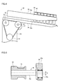
- FIG. 4 is a side view illustrating the alignment transfer section 30.
- the alignment rails 32 (that make a pair) are configured so that an upper side 32a thereof comes in contact with the step 66 of the measurement container 60 to support the measurement container 60 in a suspended state.
- the alignment rails 32 (that make a pair) are disposed in parallel with each other at an interval that is larger than the outer diameter R1 of the body 62 and is smaller than the outer diameter R2 of the neck 64.
- An upper side 34a of the upthrust plate 34 comes in contact with the bottom of the measurement container 60 that is supported by the alignment rails 32.
- the alignment transfer section 30 includes a drive pulley 70, a driver section (not illustrated in FIG. 4 ) that rotates the drive pulley 70, two driven pulleys 72, a timing belt 74 that connects the drive pulley 70 and the two driven pulleys 72, and two eccentric shafts 76 that are respectively provided to the two driven pulleys 72, and rotatably support the upthrust plate 34.
- the rotational motion of the driver section e.g., motor
- the rotational motion of the driver section is transmitted to the two eccentric shafts 76 through the drive pulley 70, the timing belt 74, and the driven pulleys 72, and converted into the upward-downward motion (vertical motion) of the upthrust plate 34.
- FIG. 5 is a schematic cross-sectional view illustrating the eccentric shaft 76.
- the driven pulley 72 is secured on a drive side 76a of the eccentric shaft 76, and a driven side 76b of the eccentric shaft 76 rotatably supports the upthrust plate 34 through a bearing.
- the driven side 76b of the eccentric shaft 76 is eccentric with respect to the drive side 76a by an eccentric amount X. Therefore, the driven side 76b produces a difference in height of 2X when the drive side 76a makes one revolution. Since the driven side 76b rotatably supports the upthrust plate 34, the upthrust plate 34 makes an upward-downward motion within the range of 2X (difference in height) when the drive side 76a makes one revolution.
- FIG. 6A is a schematic view illustrating the motion of the eccentric shaft 76 and the upthrust plate 34.
- the two eccentric shafts 76 are disposed to be parallel to each other so that the rotation angle ⁇ changes in the same phase. Therefore, the upthrust plate 34 makes an upward-downward motion (i.e., a circular motion that maintains a constant angle) while maintaining a constant slope angle when the drive side 76a of each of the two eccentric shafts 76 rotates.
- an upward-downward motion i.e., a circular motion that maintains a constant angle
- the solid lines indicate the positions of the eccentric shafts 76 and the upthrust plate 34 when the rotation angle ⁇ of the eccentric shafts 76 is 0° (or 360°), and the dotted lines indicate the positions of the eccentric shafts 76 and the upthrust plate 34 when the rotation angle ⁇ of the eccentric shafts 76 is 180°.
- the upthrust plate 34 makes an upward-downward motion in the vertical direction (i.e., the direction orthogonal to the longitudinal direction of the upthrust plate 34) within the range of 2X (difference in height) when the eccentric shafts 76 make one revolution. Since the alignment rails 32 are secured on the device, the distance between each alignment rail 32 and the upthrust plate 34 in the vertical direction changes as the upthrust plate 34 makes an upward-downward motion.
- FIG. 7 is a schematic view illustrating the motion of the measurement containers 60 that are supported by the alignment rails 32.
- FIG. 7 illustrates an example in which the upthrust plate 34 is caused to make an upward-downward motion once (i.e., the eccentric shafts 76 are caused to make one revolution) in a state in which the distance between each alignment rail 32 and the upthrust plate 34 is a maximum (i.e., a state in which the rotation angle ⁇ of the eccentric shafts 76 is 0° in FIG. 6A ) (hereinafter referred to as "start state").
- the measurement containers 60 are supported by the alignment rails 32 in a suspended state in which the step 66 thereof comes in contact with the upper side 32a of each alignment rail 32, and the bottom thereof comes in contact with the upper side 34a of the upthrust plate 34.
- the measurement containers 60 are thrust upward by the upthrust plate 34 (i.e., the step 66 is situated away from the upper side 32a of each alignment rail 32). Since the alignment rails 32 slope downward toward the end thereof (i.e., toward the supply section 40 (in the rightward direction in FIG. 7 )), the measurement containers 60 fall down toward the end of the alignment rails 32 (rotate clockwise around the bottom) due to their weight, and become still when the step 66 has come in contact with the upper side 32a of each alignment rail 32.
- the measurement containers 60 When the upthrust plate 34 has made a downward motion (i.e., has moved downward), the measurement containers 60 rotate counterclockwise around the point of contact between the step 66 and the upper side 32a of each alignment rail 32, and are supported by the alignment rails 32 in the suspended state. The measurement containers 60 thus move toward the end of the alignment rails 32 by the fall amount (moving amount L). It is possible to move the measurement containers 60 toward the end of the alignment rails 32 by repeatedly causing the upthrust plate 34 to make the above motion (upward-downward motion).
- the measurement container supply device 1 is thus configured so that the measurement containers 60 are transferred toward the end of the alignment rails 32 by causing the upthrust plate 34 to make an upward-downward motion so that a state in which the step 66 comes in contact with the upper side 32a of each alignment rail 32 and a state in which the step 66 is situated away from the upper side 32a of each alignment rail 32 are alternately repeated. This makes it possible to reliably transfer the measurement containers 60 along the alignment rails 32.
- FIG. 6A illustrates an example in which the upthrust plate 34 is caused to make an upward-downward motion by rotating the eccentric shafts 76 clockwise when the alignment rails 32 slope downward in the rightward direction
- the upthrust plate 34 may be caused to make an upward-downward motion by rotating the eccentric shafts 76 counterclockwise.
- the moving amount L of the measurement containers 60 when the eccentric shafts 76 are caused to make one revolution i.e., the upthrust plate 34 is caused to make an upward-downward motion once
- counterclockwise is larger than the moving amount L of the measurement containers 60 when the eccentric shafts 76 are caused to make one revolution clockwise.
- the upthrust plate 34 when the upthrust plate 34 is caused to make an upward-downward motion (i.e., a counterclockwise circular motion that maintains a constant angle) by rotating the eccentric shafts 76 counterclockwise, the upthrust plate 34 pushes the bottom of the measurement containers 60 in the upper left direction while the measurement containers 60 fall down clockwise due to their weight. Therefore, the moving amount L when the eccentric shafts 76 are rotated counterclockwise is larger than the moving amount L when the eccentric shafts 76 are rotated clockwise.
- an upward-downward motion i.e., a counterclockwise circular motion that maintains a constant angle
- the invention is not limited to the above embodiments. Various modifications and variations may be made of the above embodiments.
- the invention includes configurations that are substantially the same as the configurations described in connection with the above embodiments (e.g., in function, method and effect, or objective and effect).
- the invention also includes a configuration in which an unsubstantial element described in connection with the above embodiments is replaced by another element.
- the invention also includes a configuration having the same effects as those of the configurations described in connection with the above embodiments, or a configuration capable of achieving the same object as those of the configurations described in connection with the above embodiments.
- the invention further includes a configuration obtained by adding a known technique to the configurations described in connection with the above embodiments.
- the upthrust plate 34 may be biased in the vertical direction using a tension spring 80, and a solenoid 82 may be provided under the upthrust plate 34, and cause the upthrust plate 34 to make an upward-downward motion, for example.
- the upthrust plate 34 is pushed upward when power is supplied to the solenoid 82, and is moved downward due the action of the tension spring 80 when the supply of power to the solenoid 82 is stopped.
- the alignment rails 32 may be caused to make an upward-downward motion in a state in which the plate-like member is fixed.
- the measurement containers 60 are caused to fall down by moving the alignment rails 32 downward in the start state illustrated in FIG. 7 , and the alignment rails 32 are moved upward so that the measurement containers 60 are supported by the alignment rails 32 in a suspended state. The measurement containers 60 are thus moved (transferred) forward.
- the measurement container 60 that falls from the carry-out section 20 is easily fitted to the alignment rails 32, and it is possible to suppress a situation in which the measurement containers 60 are not transferred along the alignment rails 32.
- the alignment rails 32 and the upthrust plate 34 may be caused to make an upward-downward motion in an opposite phase.
- the measurement containers 60 are caused to fall down by moving the alignment rails 32 downward while moving the upthrust plate 34 upward in the start state illustrated in FIG. 7 , and the alignment rails 32 are moved upward while moving the upthrust plate 34 downward so that the measurement containers 60 are supported by the alignment rails 32 in a suspended state.
- the measurement containers 60 are thus moved (transferred) forward.
- the upper side 32a of the alignment rails 32 may be provided with steps (i.e., may have a step-like configuration) (see FIG. 9 ).
- the measurement containers 60 move forward stepwise along the alignment rails 32 each time the upthrust plate 34 or the alignment rails 32 make an upward-downward motion. This makes it possible to maintain the posture of the measurement container 60 supported by the alignment rails 32 so that the longitudinal direction thereof is parallel to the vertical axis.
- 1 measurement container supply device, 10: storage section, 20: carry-out section, 22: holding plate, 24: belt, 30: alignment transfer section, 32: alignment rail, 34: upthrust plate (plate-like member), 40: supply section, 42: support section, 50: holding section, 51: holding guide, 60: measurement container, 62: body, 64: neck, 65: opening, 66: step, 70: drive pulley, 72: driven pulley, 74: timing belt, 76: eccentric shaft, 80: tension spring, 82: solenoid
Landscapes
- Chemical & Material Sciences (AREA)
- Biochemistry (AREA)
- Physics & Mathematics (AREA)
- Health & Medical Sciences (AREA)
- Life Sciences & Earth Sciences (AREA)
- Analytical Chemistry (AREA)
- General Health & Medical Sciences (AREA)
- General Physics & Mathematics (AREA)
- Immunology (AREA)
- Pathology (AREA)
- Chemical Kinetics & Catalysis (AREA)
- Engineering & Computer Science (AREA)
- Mechanical Engineering (AREA)
- Automatic Analysis And Handling Materials Therefor (AREA)
Applications Claiming Priority (2)
| Application Number | Priority Date | Filing Date | Title |
|---|---|---|---|
| JP2013031126A JP6054769B2 (ja) | 2013-02-20 | 2013-02-20 | 測定容器供給装置 |
| PCT/JP2014/053469 WO2014129397A1 (fr) | 2013-02-20 | 2014-02-14 | Dispositif de fourniture de récipients de mesure |
Publications (2)
| Publication Number | Publication Date |
|---|---|
| EP2960656A1 true EP2960656A1 (fr) | 2015-12-30 |
| EP2960656A4 EP2960656A4 (fr) | 2016-10-12 |
Family
ID=51391190
Family Applications (1)
| Application Number | Title | Priority Date | Filing Date |
|---|---|---|---|
| EP14754652.7A Withdrawn EP2960656A4 (fr) | 2013-02-20 | 2014-02-14 | Dispositif de fourniture de récipients de mesure |
Country Status (4)
| Country | Link |
|---|---|
| US (1) | US9403645B2 (fr) |
| EP (1) | EP2960656A4 (fr) |
| JP (1) | JP6054769B2 (fr) |
| WO (1) | WO2014129397A1 (fr) |
Families Citing this family (5)
| Publication number | Priority date | Publication date | Assignee | Title |
|---|---|---|---|---|
| JP6152311B2 (ja) * | 2013-07-08 | 2017-06-21 | 日本電子株式会社 | 測定容器供給装置 |
| JP6549960B2 (ja) * | 2015-10-07 | 2019-07-24 | 日本電子株式会社 | 容器供給ユニット及び自動分析装置 |
| JP6668123B2 (ja) * | 2016-03-17 | 2020-03-18 | 株式会社日立ハイテク | 検体搬送システム |
| CN109126203B (zh) * | 2018-10-15 | 2024-12-17 | 上海昂鹭生物技术有限公司 | 一种用于有机溶液的自动过膜装置 |
| US12466711B2 (en) * | 2023-03-27 | 2025-11-11 | Toyota Motor Engineering & Manufacturing North America, Inc. | Apparatus, system, and method for automating parts unloading |
Family Cites Families (11)
| Publication number | Priority date | Publication date | Assignee | Title |
|---|---|---|---|---|
| GB701848A (en) * | 1951-08-27 | 1954-01-06 | Skoda Works Plzen Nat Corp | An automatic device for delivering articles from hoppers |
| DE2336001C3 (de) * | 1973-07-14 | 1979-05-17 | Rationator-Maschinenbau Gmbh, 6521 Hillesheim | Vorrichtung zum Vereinzeln und anschließenden Ausrichten von länglichen schmalen Teilen mit Köpfen, nämlich Aero¬ |
| JPS62289762A (ja) * | 1986-06-10 | 1987-12-16 | Tosoh Corp | 生化学反応測定装置 |
| JPH0669535B2 (ja) * | 1991-05-07 | 1994-09-07 | 幸泉 井上 | チップの自動整列機 |
| JPH0542215U (ja) * | 1991-11-18 | 1993-06-08 | 修次 秦野 | デイスポーザブルチツプ投入整列装置 |
| JP4901036B2 (ja) * | 2001-09-12 | 2012-03-21 | ベックマン コールター, インコーポレイテッド | パーツ送給装置 |
| JP4829677B2 (ja) * | 2006-05-18 | 2011-12-07 | シスメックス株式会社 | 試料分析装置 |
| JP2008096115A (ja) * | 2006-10-05 | 2008-04-24 | Sysmex Corp | キュベット |
| CN201165336Y (zh) * | 2008-01-21 | 2008-12-17 | 张建军 | 一种螺丝钉全自动包装机的自动供料机构 |
| JP5378284B2 (ja) * | 2010-03-29 | 2013-12-25 | シスメックス株式会社 | 容器供給装置及び試料分析装置 |
| JP5656625B2 (ja) * | 2010-12-29 | 2015-01-21 | シスメックス株式会社 | 試料分析装置 |
-
2013
- 2013-02-20 JP JP2013031126A patent/JP6054769B2/ja not_active Expired - Fee Related
-
2014
- 2014-02-14 US US14/768,785 patent/US9403645B2/en not_active Expired - Fee Related
- 2014-02-14 WO PCT/JP2014/053469 patent/WO2014129397A1/fr not_active Ceased
- 2014-02-14 EP EP14754652.7A patent/EP2960656A4/fr not_active Withdrawn
Also Published As
| Publication number | Publication date |
|---|---|
| JP2014160028A (ja) | 2014-09-04 |
| US20160001981A1 (en) | 2016-01-07 |
| US9403645B2 (en) | 2016-08-02 |
| WO2014129397A1 (fr) | 2014-08-28 |
| JP6054769B2 (ja) | 2016-12-27 |
| EP2960656A4 (fr) | 2016-10-12 |
Similar Documents
| Publication | Publication Date | Title |
|---|---|---|
| US9403645B2 (en) | Measuring container supplying device | |
| CA2828382C (fr) | Appareil de traitement d'echantillon | |
| KR101587359B1 (ko) | 스핀 처리 장치 | |
| US10024874B2 (en) | Measurement-container supply device | |
| EP2765426B1 (fr) | Système de traitement d'échantillon | |
| JP2015078069A (ja) | キュベット分離装置 | |
| JP2016176701A (ja) | 閉栓装置、閉栓ユニット及び閉栓方法 | |
| US20140166685A1 (en) | Apparatus and process for dispensing cuvettes | |
| JP2010074093A (ja) | 半導体ウエーハ搬送用ハンド | |
| CN104833814A (zh) | 输送装置 | |
| US12038452B2 (en) | Specimen carrier | |
| US20150226767A1 (en) | Prober | |
| KR20160117300A (ko) | 스핀 처리 장치 | |
| US9676564B2 (en) | Conveyance system and system for inspecting article to be conveyed | |
| JP6362737B2 (ja) | 自動分析装置における液体コンテナの輸送 | |
| CN109225918A (zh) | 一种内星轮上下料检测装置 | |
| CN115808145A (zh) | 一种用于晶圆厚度多点测量装置及方法 | |
| JPWO2018025608A1 (ja) | 栓処理装置およびそれを備えた検体検査自動化システム | |
| KR102213911B1 (ko) | 위치 정렬장치 | |
| US10948507B2 (en) | Specimen transport apparatus, specimen measurement apparatus, specimen transport method, and holder | |
| KR102424494B1 (ko) | 기판 스피닝 장치 | |
| EP3160652B1 (fr) | Centrifugeuse | |
| JP2006052995A (ja) | 試料容器回転装置 | |
| JP4712888B2 (ja) | 位置決め装置 | |
| JP2008311391A (ja) | ウエハ供給機能を有するウエハ位置合わせ装置 |
Legal Events
| Date | Code | Title | Description |
|---|---|---|---|
| PUAI | Public reference made under article 153(3) epc to a published international application that has entered the european phase |
Free format text: ORIGINAL CODE: 0009012 |
|
| 17P | Request for examination filed |
Effective date: 20150828 |
|
| AK | Designated contracting states |
Kind code of ref document: A1 Designated state(s): AL AT BE BG CH CY CZ DE DK EE ES FI FR GB GR HR HU IE IS IT LI LT LU LV MC MK MT NL NO PL PT RO RS SE SI SK SM TR |
|
| AX | Request for extension of the european patent |
Extension state: BA ME |
|
| DAX | Request for extension of the european patent (deleted) | ||
| A4 | Supplementary search report drawn up and despatched |
Effective date: 20160909 |
|
| RIC1 | Information provided on ipc code assigned before grant |
Ipc: G01N 35/04 20060101AFI20160905BHEP |
|
| STAA | Information on the status of an ep patent application or granted ep patent |
Free format text: STATUS: THE APPLICATION HAS BEEN WITHDRAWN |
|
| 18W | Application withdrawn |
Effective date: 20190813 |