EP2960683A1 - Étalonnage d'enregistrement de gradients de pression - Google Patents
Étalonnage d'enregistrement de gradients de pression Download PDFInfo
- Publication number
- EP2960683A1 EP2960683A1 EP15174209.5A EP15174209A EP2960683A1 EP 2960683 A1 EP2960683 A1 EP 2960683A1 EP 15174209 A EP15174209 A EP 15174209A EP 2960683 A1 EP2960683 A1 EP 2960683A1
- Authority
- EP
- European Patent Office
- Prior art keywords
- hydrophone
- receiver
- pressure signal
- pressure
- pressure signals
- Prior art date
- Legal status (The legal status is an assumption and is not a legal conclusion. Google has not performed a legal analysis and makes no representation as to the accuracy of the status listed.)
- Withdrawn
Links
Images


Classifications
-
- G—PHYSICS
- G01—MEASURING; TESTING
- G01V—GEOPHYSICS; GRAVITATIONAL MEASUREMENTS; DETECTING MASSES OR OBJECTS; TAGS
- G01V1/00—Seismology; Seismic or acoustic prospecting or detecting
- G01V1/16—Receiving elements for seismic signals; Arrangements or adaptations of receiving elements
- G01V1/20—Arrangements of receiving elements, e.g. geophone pattern
-
- G—PHYSICS
- G01—MEASURING; TESTING
- G01V—GEOPHYSICS; GRAVITATIONAL MEASUREMENTS; DETECTING MASSES OR OBJECTS; TAGS
- G01V1/00—Seismology; Seismic or acoustic prospecting or detecting
- G01V1/28—Processing seismic data, e.g. for interpretation or for event detection
- G01V1/36—Effecting static or dynamic corrections on records, e.g. correcting spread; Correlating seismic signals; Eliminating effects of unwanted energy
-
- G—PHYSICS
- G01—MEASURING; TESTING
- G01V—GEOPHYSICS; GRAVITATIONAL MEASUREMENTS; DETECTING MASSES OR OBJECTS; TAGS
- G01V1/00—Seismology; Seismic or acoustic prospecting or detecting
- G01V1/38—Seismology; Seismic or acoustic prospecting or detecting specially adapted for water-covered areas
-
- G—PHYSICS
- G01—MEASURING; TESTING
- G01V—GEOPHYSICS; GRAVITATIONAL MEASUREMENTS; DETECTING MASSES OR OBJECTS; TAGS
- G01V1/00—Seismology; Seismic or acoustic prospecting or detecting
- G01V1/38—Seismology; Seismic or acoustic prospecting or detecting specially adapted for water-covered areas
- G01V1/3808—Seismic data acquisition, e.g. survey design
Definitions
- Embodiments of the present invention generally relate to seismic data processing, and more particularly to a method for computing a pressure signal gradient.
- Seismic surveying is a method for determining the structure of subterranean formations in the earth.
- Seismic surveying typically utilizes seismic energy sources which generate seismic waves and seismic receivers which detect seismic waves.
- the seismic waves propagate into the formations in the earth, where a portion of the waves reflects from interfaces between subterranean formations.
- the amplitude and polarity of the reflected waves are determined by the differences in acoustic impedance between the rock layers comprising the subterranean formations.
- the acoustic impedance of a rock layer is the product of the acoustic propagation velocity within the layer and the density of the layer.
- the seismic receivers detect the reflected seismic waves and convert the reflected waves into representative electrical signals.
- the signals are typically transmitted by electrical, optical, radio or other means to devices which record the signals. Through analysis of the recorded signals (or traces), the shape, position and composition of the subterranean formations can be determined.
- Marine seismic surveying is a method for determining the structure of subterranean formations underlying bodies of water.
- Marine seismic surveying typically utilizes seismic energy sources and seismic receivers located in the water which are either towed behind a vessel or positioned on the water bottom from a vessel.
- the energy source is typically an explosive device or compressed air system which generates seismic energy, which then propagates as seismic waves through the body of water and into the earth formations below the bottom of the water.
- the seismic receivers typically used in marine seismic surveying are pressure sensors, such as hydrophones. Additionally, though, motion sensors, such as accelerometers may be used. Both the sources and receivers may be strategically repositioned to cover the survey area.
- Streamers of seismic receivers are often used in marine seismic surveying.
- the streamers typically contain hydrophones for recording pressure fluctuations caused by the seismic waves propagating in the water. Recently, it has been realized that the value of seismic data would be substantially enhanced if the particle motion vector of the seismic waves propagating in the water could be recorded.
- Some seismic streamers have included geophones or accelerometers for recording particle velocity or acceleration; however, such configurations have proven to be difficult due to noise and mechanical vibrations in the streamers.
- pressure gradient may be recorded or estimated, as opposed to particle velocity or acceleration.
- Pressure gradient may be recorded or estimated using closely spaced multiple streamers, such as over/under configurations.
- Unfortunately, such methods are often operationally complex and costly. Consequently, it has recently been proposed to use multiple hydrophones spaced closely apart within one streamer.
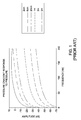
- One of the challenges encountered in using such streamers involves keeping the diameter of the streamers to a minimal to avoid negative consequences, such as drag and the like. Consequently, this requirement limits the amount of distance that can be placed between the receivers on the streamers in a pressure gradient configuration. It has been observed that the shorter the distance between the receivers, the lesser the amount of low frequencies that can be recovered.
- Various embodiments of the present invention are generally directed to a method for computing a pressure signal gradient.
- the method includes recording a plurality of pressure signals at at least one of a first receiver and a second receiver.
- the first receiver and the second receiver are disposed within a cluster.
- the method further includes recording a plurality of pressure signals at the second receiver; computing a calibration filter for removing the difference in distortions between the pressure signals recorded at the first receiver and the pressure signals recorded at the second receiver; and computing the pressure signal gradient between the pressure signals recorded at the first receiver and the pressure signals recorded at the second receiver using the calibration filter.
- the first and second receivers are disposed vertically above one another.
- the cost function ⁇ (k x , ⁇ ) is derived such that the space-time data window to which it is applied contains only up-going waves.
- the calibration filter may be determined by minimizing the cost function ⁇ (k x , ⁇ ) in a space-time data window containing only up-going waves.
- FIG. 2 illustrates a seismic vessel 200 towing a seismic source 210 and a seismic streamer 218 that may be used in connection with one or more embodiments of the invention.
- the seismic streamer 218 may be placed at about 60 meters below sea surface 212. However, those skilled in the art will recognize that the seismic streamer 218 may be placed at much shallower depth, such as 3 to 4 meters below the sea surface 212, or at depths greater than 60 meters below the sea surface 212.
- the dashed arrows 222a-d illustrate paths of seismic energy from the seismic source 210.
- Arrow 222a illustrates the initial down-going seismic energy.
- Arrow 222b illustrates a portion of the seismic energy that is transmitted through the sea floor 214.
- Arrow 222c illustrates an up-going reflection of seismic energy.
- Arrow 222d illustrates a down-going ghost reflected from the sea surface 212.
- FIG. 3 illustrates a streamer configuration 300 that may be used in connection with one or more embodiments of the invention.
- the streamer configuration 300 includes a streamer 330, which includes multiple hydrophones 332a, 332b, 332c and multiple pressure signal gradient measuring devices 334a, 334b and 334c.
- the hydrophones 332a, 332b, 332c are separated by a distance of less than about 12 meters.
- the pressure signal gradient measuring devices 334a, 334b and 334c are also separated by a distance of less than about 12 meters.
- Each pressure signal gradient measuring device 334 may be a cluster of hydrophones that includes two hydrophones that are vertically disposed one above the other. In such an embodiment, the two hydrophones may be perfectly aligned above each other.
- each pressure signal gradient measuring device 334 may be a cluster of hydrophones having three hydrophones disposed at the corners of a triangle configuration. In yet another embodiment, each pressure signal gradient measuring device 334 may be a cluster of hydrophones having four hydrophones disposed at the corners of a tetrahedron configuration.
- the streamer 330 may also include inclinometers (not shown) for measuring the orientation of the hydrophones disposed in the triangle or tetrahedron configurations.
- One advantage of using hydrophone clusters disposed in the triangle or tetrahedron configurations is the ability to recover vertical pressure signal gradients as well as the horizontal pressure signal gradients.
- FIG. 4 illustrates a flow diagram of a method 400 for computing an estimate of a pressure signal gradient in accordance with one or more embodiments of the invention.
- pressure signals are recorded at a first hydrophone within a cluster of hydrophones having two hydrophones vertically disposed one above the other.
- pressure signals are recorded at a second hydrophone within the same cluster. In this manner, the pressure signals are recorded at the first hydrophone separately from the pressure signals recorded at the second hydrophone.
- the recordings at steps 410 and 420 may be performed prior to, during or after a survey.
- One advantage of recording the pressure signals before or during a survey includes the ability to visualize or conduct a quality control on the pressure signal gradient measurements during the survey.
- the first hydrophone and the second hydrophone are vertically separated by a distance ⁇ z, which may be in a range from about 1.5 cm to about 15 cm.
- a calibration filter is computed using the recorded pressure signals.
- G( ⁇ ) represents the calibration filter
- ⁇ (k x , ⁇ ) represents the cost function
- ⁇ represents the density of water
- ⁇ represents the angular frequency
- P ⁇ 1 represents recorded pressure signals at the first hydrophone
- P ⁇ 2 represents recorded pressure signals at the second hydrophone
- ⁇ z represents the vertical distance separating the first hydrophone from the second hydrophone
- the cost function ⁇ (k x , ⁇ ) is derived such that the space-time data window to which it is applied contains only up-going waves.
- the calibration filter G( ⁇ ) may therefore be determined by minimizing the cost function ⁇ (k x , ⁇ ) in a space-time data window that contains only up-going waves.
- the calibration filter G( ⁇ ) may be determined by minimizing the cost function ⁇ (k x , ⁇ ) as a function of angular frequency. In this manner, the calibration filter is frequency dependent. Furthermore, in this embodiment, only inline propagation has been assumed and dependency on ky has been ignored.
- Equation (1) may be derived from the up-going and down-going portions of the vertical component of particle velocity V z .
- V z D 1 2 ⁇ V z + k z ⁇ ⁇ P .
- V z represents the vertical component of particle velocity
- V z D represents the down-going portion of the vertical component of particle velocity
- ⁇ represents the density of water
- ⁇ represents the angular frequency
- P represents pressure
- k z ⁇ (( ⁇ /c) 2 - k x 2 - k y 2 ), where k z represents the absolute value of the vertical wave number.
- V z - 1 i ⁇ ⁇ ⁇ ⁇ ⁇ ⁇ z ⁇ P
- ⁇ represents the density of water
- ⁇ represents the angular frequency
- P represents pressure
- ⁇ z P represents the vertical component of the pressure signal gradient
- Both F 1 ( ⁇ ) and F 2 ( ⁇ ) represent filters that are functions of frequency with a value of substantially equal to one for a substantial portion of the frequency band of interest.
- Equation (8) It can be seen from Equation (8) that the calibration problem for two closely spaced hydrophones may be solved by first determining a frequency dependent filter G( ⁇ ) in a space-time data window containing only up-going waves.
- the calibration filter is applied to the pressure signals recorded at the second hydrophone (step 440).
- the calibration filter may be applied by convolution, if the operation is performed in the time domain.
- the calibration filter may be applied by multiplication, if the operation is performed in the frequency domain. In this manner, the difference in distortions of the recorded pressure signals is removed so that the resulting pressure signals at both first and second hydrophones would have identical distortions. That is, the pressure signals recorded at both first and second hydrophones would have substantially identical characteristics.
- the calibration filter may be applied to the pressure signals recorded at the second hydrophone during the survey before computing the pressure signal gradient.
- the pressure signal gradient between the pressure signals recorded at the first and second hydrophones is computed.
- the x and y components of the pressure signal gradient may also be computed using the various above referenced methods used to compute the z component of the pressure signal gradient. Further, in order to calibrate the cross-line pressure signal gradient, the streamer may be rotated in the water and the calibration procedure may be repeated so that all components of the pressure signal gradient can be accurately calibrated. Once it has been calibrated properly in the vertical direction, the pressure signal gradient configuration is equally well suited for recording vertical as well as cross-line pressure signal gradient.
- the pressure signal gradient may be used in conventional seismic data processing, including deghosting, removing multiples and imaging.
- method 400 may be repeated for each pressure gradient configuration in the streamer.
- method 400 may be repeated for each pressure gradient configuration in the common receiver domain or in the common shot domain by using compact space filters that act on the recorded pressure signals as described in commonly assigned WO 2004/029662 , which is incorporated herein by reference.
- the method for computing an estimate of a pressure signal gradient is described with reference to a cluster of hydrophones having two hydrophones, other embodiments of the invention contemplate methods for computing pressure signal gradient estimates for a cluster of hydrophones having more than two hydrophones, such as, three or four hydrophones.
- embodiments of the invention are described with reference to a single streamer configuration, such as streamer 330, other embodiments of the invention may also be applied to multiple streamer configurations, such as over/under streamer configurations.
- embodiments of the invention are described herein with reference to hydrophones, other embodiments contemplate other types of receivers commonly known by persons of ordinary skill in the art.
- various embodiments of the invention discussed herein may be applied to seismic data acquired in a seabed seismic setting, a borehole seismic setting or an over/under seismic setting.
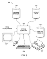
- FIG. 5 illustrates a computer network 500, into which embodiments of the invention may be implemented.
- the computer network 500 includes a system computer 530, which may be implemented as any conventional personal computer or workstation, such as a UNIX-based workstation.
- the system computer 530 is in communication with disk storage devices 529, 531, and 533, which may be external hard disk storage devices. It is contemplated that disk storage devices 529, 531, and 533 are conventional hard disk drives, and as such, will be implemented by way of a local area network or by remote access. Of course, while disk storage devices 529, 531, and 533 are illustrated as separate devices, a single disk storage device may be used to store any and all of the program instructions, measurement data, and results as desired.
- seismic data such as pressure signals
- the system computer 530 may retrieve the appropriate data from the disk storage device 531 to perform program instructions that correspond to the pressure signal gradient computation methods described herein.
- the program instructions may be written in a computer programming language, such as C++, Java and the like.
- the program instructions may be stored in a computer-readable memory, such as program disk storage device 533.
- the memory medium storing the program instructions may be of any conventional type used for the storage of computer programs, including hard disk drives, floppy disks, CD-ROMs and other optical media, magnetic tape, and the like.
- the system computer 530 presents output primarily onto graphics display 527, or alternatively via printer 528.
- the system computer 530 may store the results of the methods described above on disk storage 529, for later use and further analysis.
- the keyboard 526 and the pointing device (e.g., a mouse, trackball, or the like) 525 may be provided with the system computer 530 to enable interactive operation.
- the system computer 530 may be located at a data center remote from the survey region.
- the system computer 530 is in communication with hydrophones (either directly or via a recording unit, not shown), to receive signals indicative of the reflected seismic energy. These signals, after conventional formatting and other initial processing, are stored by the system computer 530 as digital data in the disk storage 531 for subsequent retrieval and processing in the manner described above. While Figure 5 illustrates the disk storage 531 as directly connected to the system computer 530, it is also contemplated that the disk storage device 531 may be accessible through a local area network or by remote access.
- disk storage devices 529, 531 are illustrated as separate devices for storing seismic data and analysis results, the disk storage devices 529, 531 may be implemented within a single disk drive (either together with or separately from program disk storage device 533), or in any other conventional manner as will be fully understood by one of skill in the art having reference to this specification.
- An aspect of the invention provides a method for computing a pressure signal gradient, comprising: recording a plurality of pressure signals at at least one of a first receiver and a second receiver; recording a plurality of pressure signals at the second receiver, wherein the first receiver and the second receiver are disposed within a cluster; and computing the pressure signal gradient between the pressure signals recorded at the first receiver and the pressure signals recorded at the second receiver.
- Computing the pressure signal gradient may comprise removing the difference in distortions between the pressure signals recorded at the first receiver and the pressure signals recorded at the second receiver.
- Computing the pressure signal gradient may comprise computing a calibration filter using the recorded pressure signals.
- the calibration filter may be frequency dependent.
- the cost function ⁇ (k x , ⁇ ) may be minimized in a space-time data window that contains only up-going waves.
- Computing the pressure signal gradient may further comprise applying the calibration filter to the pressure signals recorded at the second receiver.
- the calibration filter may be applied to the pressure signals recorded at the second receiver by convolution, or the calibration filter may be applied to the pressure signals recorded at the second receiver by multiplication.
- Computing the pressure signal gradient may further comprise subtracting the calibrated pressure signals recorded at the second receiver from the pressures signals recorded at the first receiver.
- Computing the pressure signal gradient may further comprise: subtracting the calibrated pressure signals recorded at the second receiver from the pressure signals recorded at the first receiver; and dividing the result by a distance between the first receiver and the second receiver.
- the pressure signals may be recorded at the first receiver separately from the pressure signals recorded at the second receiver.
- the pressure signals are recorded prior to a survey, during a survey, or after a survey.
- the first and second receivers may be hydrophones.
- the method may further comprise applying the pressure signal gradient to seismic data acquired in a towed marine seismic setting, to seismic data acquired in a seabed seismic setting, to seismic data acquired in a borehole seismic setting, or to seismic data acquired in an over/under multistreamer seismic setting.
- the first receiver may be separated from the second receiver by a distance from about 2 cm to about 15 cm.
- the first receiver may be vertically disposed above the second receiver.
- the method may further comprise: recording a plurality of pressure signals at a third receiver; and computing the pressure signal gradient between the pressure signals recorded at the first receiver, the pressure signals recorded at the second receiver and the pressure signals recorded at the third receiver.
- the method may further comprise: recording a plurality of pressure signals at a third receiver; recording a plurality of pressure signals at a fourth receiver; and computing the pressure signal gradient between the pressure signals recorded at the first receiver, the pressure signals recorded at the second receiver, the pressure signals recorded at the third receiver and the pressure signals recorded at the fourth receiver.
- a second aspect of the invention provides a method for computing a pressure signal gradient, comprising: recording a plurality of pressure signals at at least one of a first receiver and a second receiver; recording a plurality of pressure signals at the second receiver, wherein the first receiver and the second receiver are disposed within a cluster; computing a calibration filter for removing the difference in distortions between the pressure signals recorded at the first receiver and the pressure signals recorded at the second receiver; and computing the pressure signal gradient between the pressure signals recorded at the first receiver and the pressure signals recorded at the second receiver using the calibration filter.
- the cost function ⁇ (k x , ⁇ ) may be minimized in a space-time data window that contains only up-going waves.
Landscapes
- Life Sciences & Earth Sciences (AREA)
- Physics & Mathematics (AREA)
- Remote Sensing (AREA)
- Engineering & Computer Science (AREA)
- Geology (AREA)
- Environmental & Geological Engineering (AREA)
- Acoustics & Sound (AREA)
- General Life Sciences & Earth Sciences (AREA)
- General Physics & Mathematics (AREA)
- Geophysics (AREA)
- Oceanography (AREA)
- Geophysics And Detection Of Objects (AREA)
- Measuring Fluid Pressure (AREA)
Applications Claiming Priority (2)
| Application Number | Priority Date | Filing Date | Title |
|---|---|---|---|
| US11/079,704 US7319636B2 (en) | 2005-03-14 | 2005-03-14 | Calibration of pressure gradient recordings |
| EP06270030.7A EP1703303B1 (fr) | 2005-03-14 | 2006-03-14 | Étalonnage d'enregistrement de gradient de pression |
Related Parent Applications (2)
| Application Number | Title | Priority Date | Filing Date |
|---|---|---|---|
| EP06270030.7A Division-Into EP1703303B1 (fr) | 2005-03-14 | 2006-03-14 | Étalonnage d'enregistrement de gradient de pression |
| EP06270030.7A Division EP1703303B1 (fr) | 2005-03-14 | 2006-03-14 | Étalonnage d'enregistrement de gradient de pression |
Publications (1)
| Publication Number | Publication Date |
|---|---|
| EP2960683A1 true EP2960683A1 (fr) | 2015-12-30 |
Family
ID=36292708
Family Applications (2)
| Application Number | Title | Priority Date | Filing Date |
|---|---|---|---|
| EP06270030.7A Expired - Fee Related EP1703303B1 (fr) | 2005-03-14 | 2006-03-14 | Étalonnage d'enregistrement de gradient de pression |
| EP15174209.5A Withdrawn EP2960683A1 (fr) | 2005-03-14 | 2006-03-14 | Étalonnage d'enregistrement de gradients de pression |
Family Applications Before (1)
| Application Number | Title | Priority Date | Filing Date |
|---|---|---|---|
| EP06270030.7A Expired - Fee Related EP1703303B1 (fr) | 2005-03-14 | 2006-03-14 | Étalonnage d'enregistrement de gradient de pression |
Country Status (6)
| Country | Link |
|---|---|
| US (1) | US7319636B2 (fr) |
| EP (2) | EP1703303B1 (fr) |
| GB (1) | GB2424277B (fr) |
| MX (1) | MXPA06002869A (fr) |
| NO (1) | NO20061159L (fr) |
| RU (1) | RU2457508C2 (fr) |
Families Citing this family (17)
| Publication number | Priority date | Publication date | Assignee | Title |
|---|---|---|---|---|
| GB2410551B (en) * | 2004-01-30 | 2006-06-14 | Westerngeco Ltd | Marine seismic acquisition system |
| US7800977B2 (en) | 2004-06-01 | 2010-09-21 | Westerngeco L.L.C. | Pre-stack combining of over/under seismic data |
| GB2428089B (en) | 2005-07-05 | 2008-11-05 | Schlumberger Holdings | Borehole seismic acquisition system using pressure gradient sensors |
| US7466625B2 (en) * | 2006-06-23 | 2008-12-16 | Westerngeco L.L.C. | Noise estimation in a vector sensing streamer |
| US7480204B2 (en) * | 2006-07-07 | 2009-01-20 | Westerngeco L.L.C. | Seismic data processing |
| US7379385B2 (en) * | 2006-07-26 | 2008-05-27 | Westerngeco L.L.C. | Processing of seismic data acquired using over/under streamers and/or over/under sources |
| US8593907B2 (en) * | 2007-03-08 | 2013-11-26 | Westerngeco L.L.C. | Technique and system to cancel noise from measurements obtained from a multi-component streamer |
| US7679991B2 (en) * | 2007-03-16 | 2010-03-16 | Westerngeco L. L. C. | Processing of seismic data acquired using twin over/under streamers |
| US9279899B2 (en) * | 2007-07-18 | 2016-03-08 | Westerngeco L.L.C. | System and technique to estimate physical propagation parameters associated with a seismic survey |
| US20090040872A1 (en) * | 2007-08-09 | 2009-02-12 | Jahir Pabon | Removing Vibration Noise from Multicomponent Streamer Measurements |
| US7630276B2 (en) * | 2008-03-27 | 2009-12-08 | Fairfield Industries Incorporated | Method for determination of differential transfer function between two closely spaced hydrophones |
| WO2010059304A1 (fr) * | 2008-11-21 | 2010-05-27 | Exxonmobil Upstream Research Company | Transducteur à réponse de diffusion de porteuse exempte de charge permettant de détecter les gradients |
| US8902699B2 (en) * | 2010-03-30 | 2014-12-02 | Pgs Geophysical As | Method for separating up and down propagating pressure and vertical velocity fields from pressure and three-axial motion sensors in towed streamers |
| US9019797B2 (en) | 2010-06-10 | 2015-04-28 | Westerngeco L.L.C. | Deghosting using measurement data from seismic sensors |
| CA2806192A1 (fr) | 2010-07-26 | 2012-02-02 | Exxonmobil Upstream Research Company | Procede d'acquisition sismique pour separation de mode |
| RU2562711C2 (ru) * | 2010-09-02 | 2015-09-10 | Ион Геофизикал Корпорейшн | Многокомпонентный датчик акустических волн и способы |
| CN110207809B (zh) * | 2019-05-31 | 2020-04-14 | 浙江大学 | 基于空间频域平滑技术的换能器转移阻抗校准装置 |
Citations (7)
| Publication number | Priority date | Publication date | Assignee | Title |
|---|---|---|---|---|
| US3548631A (en) * | 1969-07-30 | 1970-12-22 | Us Navy | Pressure gradient hydrophone calibrator |
| US3803543A (en) * | 1967-03-17 | 1974-04-09 | Us Navy | Remotely formed multibeam hydrophone system |
| US4692907A (en) * | 1984-12-10 | 1987-09-08 | Western Geophysical Company Of America | Means for maintaining a fixed relative orientation of two sensors |
| US4995013A (en) * | 1988-12-20 | 1991-02-19 | Thomson-Csf | Directional modular linear hydrophonic antenna |
| US6041127A (en) * | 1997-04-03 | 2000-03-21 | Lucent Technologies Inc. | Steerable and variable first-order differential microphone array |
| WO2004029662A1 (fr) | 2002-09-27 | 2004-04-08 | Westerngeco Seismic Holdings Limited | Traitement de donnees sismiques |
| US20040141355A1 (en) * | 2001-03-13 | 2004-07-22 | Robertsson Johan O.A. | Determining the orientation of a seismic receiver, a seismic receiver, and a method or seismic surveying |
Family Cites Families (20)
| Publication number | Priority date | Publication date | Assignee | Title |
|---|---|---|---|---|
| US2757356A (en) * | 1954-01-08 | 1956-07-31 | Texas Instruments Inc | Method and apparatus for canceling reverberations in water layers |
| US3286224A (en) * | 1965-02-15 | 1966-11-15 | Gen Dynamics Corp | Acoustic direction finding system |
| US4437175A (en) | 1981-11-20 | 1984-03-13 | Shell Oil Company | Marine seismic system |
| US4520467A (en) | 1982-03-18 | 1985-05-28 | Shell Oil Company | Marine seismic system |
| US4752916A (en) * | 1984-08-28 | 1988-06-21 | Dan Loewenthal | Method and system for removing the effect of the source wavelet from seismic data |
| US4648082A (en) * | 1985-03-04 | 1987-03-03 | Western Geophysical Company Of America | Marine acoustic gradient sensor |
| US4789968A (en) * | 1987-04-24 | 1988-12-06 | Exxon Production Research Company | Method and system for seismic exploration employing a dual-dipole hydrophone streamer |
| US4935903A (en) | 1989-05-30 | 1990-06-19 | Halliburton Geophysical Services, Inc. | Reinforcement of surface seismic wavefields |
| EG19158A (en) * | 1989-08-25 | 1996-02-29 | Halliburton Geophys Service | System for attenuation of water-column reverberation |
| US5051961A (en) * | 1989-10-26 | 1991-09-24 | Atlantic Richfield Company | Method and apparatus for seismic survey including using vertical gradient estimation to separate downgoing seismic wavefield |
| US5365492A (en) * | 1993-08-04 | 1994-11-15 | Western Atlas International, Inc. | Method for reverberation suppression |
| US5581514A (en) * | 1993-11-10 | 1996-12-03 | Geco-Prakla, Inc. | Surface seismic profile system and method using vertical sensor |
| GB9800741D0 (en) * | 1998-01-15 | 1998-03-11 | Geco As | Multiple attenuation of multi-component sea-bottom data |
| GB9906456D0 (en) * | 1999-03-22 | 1999-05-12 | Geco Prakla Uk Ltd | Method and system for reducing effects of sea surface ghost contamination in seismic data |
| US6477470B2 (en) * | 2000-12-01 | 2002-11-05 | Pgs Americas, Inc. | Method and system for deghosting |
| GB2384068B (en) | 2002-01-11 | 2005-04-13 | Westerngeco Ltd | A method of and apparatus for processing seismic data |
| US7123543B2 (en) | 2003-07-16 | 2006-10-17 | Pgs Americas, Inc. | Method for seismic exploration utilizing motion sensor and pressure sensor data |
| GB2410551B (en) * | 2004-01-30 | 2006-06-14 | Westerngeco Ltd | Marine seismic acquisition system |
| US7359283B2 (en) | 2004-03-03 | 2008-04-15 | Pgs Americas, Inc. | System for combining signals of pressure sensors and particle motion sensors in marine seismic streamers |
| US7800977B2 (en) * | 2004-06-01 | 2010-09-21 | Westerngeco L.L.C. | Pre-stack combining of over/under seismic data |
-
2005
- 2005-03-14 US US11/079,704 patent/US7319636B2/en not_active Expired - Fee Related
-
2006
- 2006-03-10 NO NO20061159A patent/NO20061159L/no not_active Application Discontinuation
- 2006-03-13 RU RU2006107884/28A patent/RU2457508C2/ru not_active IP Right Cessation
- 2006-03-14 GB GB0605088A patent/GB2424277B/en not_active Expired - Fee Related
- 2006-03-14 EP EP06270030.7A patent/EP1703303B1/fr not_active Expired - Fee Related
- 2006-03-14 MX MXPA06002869A patent/MXPA06002869A/es active IP Right Grant
- 2006-03-14 EP EP15174209.5A patent/EP2960683A1/fr not_active Withdrawn
Patent Citations (7)
| Publication number | Priority date | Publication date | Assignee | Title |
|---|---|---|---|---|
| US3803543A (en) * | 1967-03-17 | 1974-04-09 | Us Navy | Remotely formed multibeam hydrophone system |
| US3548631A (en) * | 1969-07-30 | 1970-12-22 | Us Navy | Pressure gradient hydrophone calibrator |
| US4692907A (en) * | 1984-12-10 | 1987-09-08 | Western Geophysical Company Of America | Means for maintaining a fixed relative orientation of two sensors |
| US4995013A (en) * | 1988-12-20 | 1991-02-19 | Thomson-Csf | Directional modular linear hydrophonic antenna |
| US6041127A (en) * | 1997-04-03 | 2000-03-21 | Lucent Technologies Inc. | Steerable and variable first-order differential microphone array |
| US20040141355A1 (en) * | 2001-03-13 | 2004-07-22 | Robertsson Johan O.A. | Determining the orientation of a seismic receiver, a seismic receiver, and a method or seismic surveying |
| WO2004029662A1 (fr) | 2002-09-27 | 2004-04-08 | Westerngeco Seismic Holdings Limited | Traitement de donnees sismiques |
Also Published As
| Publication number | Publication date |
|---|---|
| US7319636B2 (en) | 2008-01-15 |
| RU2457508C2 (ru) | 2012-07-27 |
| RU2006107884A (ru) | 2007-09-20 |
| GB0605088D0 (en) | 2006-04-26 |
| EP1703303B1 (fr) | 2016-08-24 |
| GB2424277A (en) | 2006-09-20 |
| MXPA06002869A (es) | 2006-09-18 |
| GB2424277B (en) | 2008-09-17 |
| EP1703303A3 (fr) | 2008-07-23 |
| US20060203611A1 (en) | 2006-09-14 |
| EP1703303A2 (fr) | 2006-09-20 |
| NO20061159L (no) | 2006-09-15 |
Similar Documents
| Publication | Publication Date | Title |
|---|---|---|
| US10989825B2 (en) | Method and system for determining source signatures after source ghost removal | |
| CN102016643B (zh) | 用于衰减双传感器地震拖缆中的低频噪声的方法 | |
| US7768869B2 (en) | Method for deghosting and water layer multiple reflection attenuation in marine seismic data | |
| US7616523B1 (en) | Method for combining pressure and motion seismic signals from streamers where sensors are not at a common depth | |
| US7872942B2 (en) | Method for imaging a sea-surface reflector from towed dual-sensor streamer data | |
| EP2420864B1 (fr) | Procédé de décomposition d'ondes utilisant des capteurs de mouvement à plusieurs composants | |
| US7359283B2 (en) | System for combining signals of pressure sensors and particle motion sensors in marine seismic streamers | |
| EP1703303B1 (fr) | Étalonnage d'enregistrement de gradient de pression | |
| CN103959099B (zh) | 使用梯度传感器的波场分离 | |
| CN102207553A (zh) | 用于分离向上和向下传播的压力和垂直速度场的方法 | |
| US7864628B2 (en) | Flexural wave attenuation | |
| US20080270035A1 (en) | System and Technique to Remove Perturbation Noise from Seismic Sensor Data | |
| CN101881836A (zh) | 用于根据地震信号来计算地震属性的方法 | |
| CN102121997A (zh) | 用于海洋地震拖缆数据的完全带宽源消幻影的方法 | |
| EP2299296B1 (fr) | Procédé de combinaison de signaux de pression et capteurs de mouvement de particules dans des flûtes sismiques marines | |
| US20230114991A1 (en) | Seismic wavefield modeling honoring avo/ava with applications to full waveform inversion and least-squares imaging | |
| US20080144435A1 (en) | Deep low frequency towed-array marine survey | |
| Poletto* et al. | Seismic acquisition and processing of onshore dual fields by a reciprocal experiment |
Legal Events
| Date | Code | Title | Description |
|---|---|---|---|
| PUAI | Public reference made under article 153(3) epc to a published international application that has entered the european phase |
Free format text: ORIGINAL CODE: 0009012 |
|
| AC | Divisional application: reference to earlier application |
Ref document number: 1703303 Country of ref document: EP Kind code of ref document: P |
|
| AK | Designated contracting states |
Kind code of ref document: A1 Designated state(s): FR |
|
| 17P | Request for examination filed |
Effective date: 20160624 |
|
| RBV | Designated contracting states (corrected) |
Designated state(s): FR |
|
| GRAP | Despatch of communication of intention to grant a patent |
Free format text: ORIGINAL CODE: EPIDOSNIGR1 |
|
| INTG | Intention to grant announced |
Effective date: 20160822 |
|
| STAA | Information on the status of an ep patent application or granted ep patent |
Free format text: STATUS: GRANT OF PATENT IS INTENDED |
|
| STAA | Information on the status of an ep patent application or granted ep patent |
Free format text: STATUS: THE APPLICATION IS DEEMED TO BE WITHDRAWN |
|
| 18D | Application deemed to be withdrawn |
Effective date: 20170103 |