EP2960918A1 - Schalter und knopf dafür - Google Patents
Schalter und knopf dafür Download PDFInfo
- Publication number
- EP2960918A1 EP2960918A1 EP13875799.2A EP13875799A EP2960918A1 EP 2960918 A1 EP2960918 A1 EP 2960918A1 EP 13875799 A EP13875799 A EP 13875799A EP 2960918 A1 EP2960918 A1 EP 2960918A1
- Authority
- EP
- European Patent Office
- Prior art keywords
- pushing rod
- button
- bridge
- elastic member
- tube portion
- Prior art date
- Legal status (The legal status is an assumption and is not a legal conclusion. Google has not performed a legal analysis and makes no representation as to the accuracy of the status listed.)
- Granted
Links
Images

Classifications
-
- H—ELECTRICITY
- H01—ELECTRIC ELEMENTS
- H01H—ELECTRIC SWITCHES; RELAYS; SELECTORS; EMERGENCY PROTECTIVE DEVICES
- H01H13/00—Switches having rectilinearly-movable operating part or parts adapted for pushing or pulling in one direction only, e.g. push-button switch
- H01H13/02—Details
- H01H13/12—Movable parts; Contacts mounted thereon
- H01H13/14—Operating parts, e.g. push-button
-
- H—ELECTRICITY
- H01—ELECTRIC ELEMENTS
- H01H—ELECTRIC SWITCHES; RELAYS; SELECTORS; EMERGENCY PROTECTIVE DEVICES
- H01H13/00—Switches having rectilinearly-movable operating part or parts adapted for pushing or pulling in one direction only, e.g. push-button switch
- H01H13/02—Details
- H01H13/12—Movable parts; Contacts mounted thereon
- H01H13/20—Driving mechanisms
-
- H—ELECTRICITY
- H01—ELECTRIC ELEMENTS
- H01H—ELECTRIC SWITCHES; RELAYS; SELECTORS; EMERGENCY PROTECTIVE DEVICES
- H01H13/00—Switches having rectilinearly-movable operating part or parts adapted for pushing or pulling in one direction only, e.g. push-button switch
- H01H13/50—Switches having rectilinearly-movable operating part or parts adapted for pushing or pulling in one direction only, e.g. push-button switch having a single operating member
- H01H13/64—Switches having rectilinearly-movable operating part or parts adapted for pushing or pulling in one direction only, e.g. push-button switch having a single operating member wherein the switch has more than two electrically distinguishable positions, e.g. multi-position push-button switches
- H01H13/66—Switches having rectilinearly-movable operating part or parts adapted for pushing or pulling in one direction only, e.g. push-button switch having a single operating member wherein the switch has more than two electrically distinguishable positions, e.g. multi-position push-button switches the operating member having only two positions
-
- H—ELECTRICITY
- H01—ELECTRIC ELEMENTS
- H01H—ELECTRIC SWITCHES; RELAYS; SELECTORS; EMERGENCY PROTECTIVE DEVICES
- H01H2221/00—Actuators
- H01H2221/036—Return force
- H01H2221/044—Elastic part on actuator or casing
Definitions
- the present invention relates to a switch and a button thereof.
- Switches in the prior art generally comprise a button and a three-position contact module, wherein the button is used to control the three-position contact module in order to change the state of the contacts, e.g. a similar structure is disclosed in US patent announcement no. US 4282414 .
- the structure of the three-position contact module is rather complex, with poor stability and high costs.
- an existing button cannot achieve three-position on/off switching if an ordinary two-position contact module is used.
- the present invention is intended to provide a button which can be used to control a two-position contact module to achieve three-position on/off switching.
- the present invention is also intended to provide a switch which uses the button.
- a button comprising a housing, an operating portion, a mount, a first pushing rod, a bridge, an elastic member and a second pushing rod;
- the mount is mounted in the housing;
- the first pushing rod is movably disposed in the mount;
- a projection is formed on the first pushing rod;
- the bridge and the operating portion are disposed on two ends of the first pushing rod;
- the second pushing rod is movably disposed on the bridge and is acted upon by the elastic member;
- a step is formed in the housing; the step is located between the mount and the bridge;
- the elastic member is disposed on the first pushing rod and is located between the projection and the step; the first pushing rod can slide relative to the mount under the action of the operating portion or the elastic member, and drive the bridge and/or the second pushing rod to move.
- the elastic member is a spring surrounding the first pushing rod.
- the button further comprises a spacer; the spacer surrounds the first pushing rod and is sandwiched between the elastic member and the step.
- the bridge comprises a body, a sidewall and a gap; the first pushing rod is connected to the body; the sidewall is disposed on the body; the gap is formed in the sidewall and the body; two recessed portions are formed on an inner surface of the sidewall and located on two sides of the gap;the second pushing rod comprises a base body and two extension arms; the base body is located in the gap of the bridge and in contact with the spacer; the two extension arms are disposed on two sides of the base body, located inside the bridge and respectively in contact with the two recessed portions.
- the sidewall is arcuate; the two extension arms are arcuate.
- the bridge further comprises two extending portions; the two extending portions are disposed perpendicularly on the body; a guiding structure is formed on an outer surface of each of the two extending portions.
- the housing comprises a first tube portion and a second tube portion; the diameter of the first tube portion is larger than the diameter of the second tube portion; the operating portion and the mount are located in the first tube portion; the second tube portion is in communication with the first tube portion; the bridge, the elastic member and the second pushing rod are located in the second tube portion; the step is formed in the second tube portion.
- a fixing portion is provided on an inner surface of the first tube portion; the mount is mounted in the first tube portion by means of the fixing portion.
- a switch comprising a generic two-position contact module; the generic two-position contact module comprises a normally-open contact and a normally-closed contact; the switch also comprises the button described above; the first pushing rod of the button drives the bridge of the button to move in order to control the on/off switching of the normally-open contact; movement of the second pushing rod of the button controls the on/off switching of the normally-closed contact.
- the button has an equilibrium position; when the button is in the equilibrium position, the second pushing rod is in contact with the bridge, and the second pushing rod triggers the disconnection of the normally-closed contact under the action of the elastic member of the button; the normally-open contact is in a disconnected state; the button is pressed so that the first pushing rod slides towards the generic two-position contact module, and so that the elastic member is compressed; the bridge moves with the first pushing rod until the bridge triggers the connection of the normally-open contact; the second pushing rod is supported by the normally-closed contact and so does not move; when the button is released, the button returns to the equilibrium position, under the action of the restoring elastic force of the elastic member; pulling the button up from the equilibrium position causes the first pushing rod to move in a direction away from the generic two-position contact module, and the elastic member to be compressed; the bridge drives the second pushing rod to move together with the bridge in the direction away from the generic two-position contact module, until the second pushing rod triggers through the connection of the normally-closed contact.
- the button in an embodiment of the present invention and the switch which uses the button can use the first pushing rod to drive the bridge to move so as to control the on/off switching of the normally-open contact of the generic two-position contact module, and use the second pushing rod mounted on the bridge to control the on/off switching of the normally-closed contact of the generic two-position contact module, thereby achieving three-position on/off switching.
- the generic two-position contact module has a simple structure, and cost body, while mounting and replacement are convenient.
- a generic two-position contact module with a lower cost can be used to achieve three-position on/off switching, with lower costs and convenient mounting and replacement.
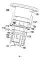
- Fig. 1 shows a schematic diagram of a button 100 in an embodiment of the present invention.
- the button 100 comprises a housing 110, an operating portion 120, a mount 130, a first pushing rod 150, a bridge 160, an elastic member 170, a spacer 180 and a second pushing rod 190.
- the mount 130 is mounted in the housing 110; the first pushing rod 150 is movably disposed in the mount 130; the bridge 160 is disposed on the first pushing rod 150; the second pushing rod 190 is movably disposed on the bridge 160; the elastic member 170 and spacer 180 are disposed on the first pushing rod 150 and are located between the mount 130 and the bridge 160; the first pushing rod 150 can slide relative to the mount 130 under the action of the operating portion 120 or elastic member 170, and drive the bridge 160 and/or second pushing rod 190 to move.
- the housing 110 is substantially tubular, comprising a first tube portion 112 and a second tube portion 113.
- the diameter of the first tube portion 112 is larger than the diameter of the second tube portion 113.
- the first tube portion 112 may be used to accommodate the operating portion 120 and mount 130.
- a fixing portion 1121 is provided on an inner surface of the first tube portion 112, for mounting the mount 130 in the first tube portion 112.
- the second tube portion 113 is in communication with the first tube portion 112, and may be used to accommodate the first pushing rod 150, bridge 160, elastic member 170, spacer 180 and second pushing rod 190.
- a step 1132 is provided on an inner surface of the second tube portion 113, for defining the position of the spacer 180.
- the first pushing rod 150 is disposed in the housing 110 and movably disposed in the mount 130.
- the first pushing rod 150 extends substantially in an axial direction D1 of the housing 110.
- the first pushing rod 150 comprises a first end and a second end.
- a first end of the first pushing rod 150 is located in the first tube portion 112, and connected to the operating portion 120; thus, the operating portion 120 can drive the first pushing rod 150 to slide in the housing 110 relative to the mount 130 in the axial direction D1.
- a second end of the first pushing rod 150 is located in the second tube portion 113.
- a projection 152 in contact with an upper part of the elastic member 170 (when the button 100 is in the position shown in Fig. 1 ) can be provided on the first pushing rod 150, for applying an acting force to the elastic member 170.
- the bridge 160 is disposed on the second end of the first pushing rod 150 and is located in the second tube portion 113.
- the bridge 160 can move together with the first pushing rod 150.
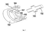
- the bridge 160 comprises a body 162, two extending portions 163 and a sidewall 165.
- the body 162 is substantially annular, may be used for mounting the first pushing rod 150, and may be used for triggering the connection of a normally-open contact in a two-position contact module.
- the two extending portions 163 are disposed on the body 162 in a substantially perpendicular manner, and can serve a guiding function.
- a guiding structure 164 such as a groove (as shown in Fig.
- a protrusion may be formed on an outer surface of the extending portion 163; in this case, a protrusion or groove may be correspondingly disposed on an inner surface of the second tube portion 113, in order to guide the sliding of the bridge 160 in the second tube portion 113.
- the sidewall 165 is disposed on the body 110 in a substantially perpendicular manner and is located between the two extending portions 163. In one embodiment, the sidewall 165 is arranged along a periphery of the body 110 and is arcuate.
- a gap 166 is formed in the sidewall 165 and body 110; two recessed portions 167 are formed on an inner surface of the sidewall 165 and located on two sides of the gap 166, so that parts of the sidewall 165 which are close to the gap 166 become a thin-walled structure to mount the second pushing rod 190.
- the elastic member 170 and spacer 180 are disposed on the first pushing rod 150 and located between the mount 130 and the step 1132 of the second tube portion 113.
- the elastic member 170 is a spring which surrounds the first pushing rod 150; one end of the elastic member 170 is in contact with the projection 152 on the first pushing rod 150, while the other end is in contact with the spacer 180.
- the spacer 180 surrounds the first pushing rod 150 and is sandwiched between the elastic member 170 and the step 1132 of the second tube portion 113.
- the second pushing rod 190 comprises a base body 192 and two extension arms 193.
- the base body 192 is substantially rod-shaped, and can be disposed in the gap 166 of the bridge 160.
- the two extension arms 193 are disposed on two sides of the base body 192, and are disposed to correspond to the two recessed portions 167 on the bridge 160.
- the two extension arms 193 are located inside the bridge 160 and are respectively in contact with the two recessed portions 167, so that the second pushing rod 190 is slidably disposed on the bridge 160.
- the two extension arms 193 are arcuate.
- buttons 100 in an embodiment of the present invention.
- a method of using the button 100 is explained briefly below, taking as an example the use of the button 100 to control a generic two-position contact module (i.e. the button 100 and the generic two-position contact module form a switch) to achieve three-position on/off switching.
- a generic two-position contact module i.e. the button 100 and the generic two-position contact module form a switch
- the generic two-position contact module comprises a normally-open contact and a normally-closed contact.
- the button 100 When the button 100 is in the position shown in Fig. 1 , the button 100 is in an equilibrium position; at this time, a lower part of the second pushing rod 190 is in contact with the body 162 of the bridge 160, while an upper part of the second pushing rod 190 is acted upon by the elastic member 170 and the spacer 180 and is thereby held in the position shown in Fig. 1 .
- a bottom end or free end of the second pushing rod 190 can be made to trigger the disconnection of the normally-closed contact of the two-position contact module, i.e. both the normally-open contact and the normally-closed contact of the generic two-position contact module are in a disconnected state.
- the button 100 is pressed so that the first pushing rod 150 slides in the mount 130 towards the generic two-position contact module in the direction from the first tube portion 112 to the second tube portion 113; at the same time, the bridge 160 also slides in the second tube portion 113 until the bridge 160 triggers the connection of the normally-open contact of the generic two-position contact module.
- the projection 152 on the first pushing rod 150 compresses the elastic member 170; since the bottom end or free end of the second pushing rod 190 is supported by the normally-closed contact of the generic two-position contact module (the normally-closed contact may have a spring structure, wherein the elastic force of the spring can support the second pushing rod 190) and so cannot move, the normally-closed contact of the generic two-position contact module remains in a disconnected state, whereas the normally-open contact of the generic two-position contact module is in a connected state.
- the button 100 is released, the first pushing rod 150 and bridge 160 return to the position shown in Fig. 1 , under the action of the restoring elastic force of the elastic member 170.
- the first pushing rod 150 moves in the mount 130 in the direction from the second tube portion 113 to the first tube portion 112; during this process, the elastic member 170 is compressed, and the bridge 160 can drive the second pushing rod 190 to move together with the bridge away from the generic two-position contact module in the direction from the second tube portion 113 to the first tube portion 112, until connection of the normally-closed contact of the generic two-position contact module is triggered.
- the normally-closed contact of the generic two-position contact module is in a connected state, whereas the normally-open contact of the generic two-position contact module is in a disconnected state.
- the button 100 in an embodiment of the present invention can use the first pushing rod 150 to drive the bridge 160 to move so as to control the on/off switching of the normally-open contact of the generic two-position contact module, and use the second pushing rod 190 mounted on the bridge 160 to control the on/off switching of the normally-closed contact of the generic two-position contact module, thereby achieving three-position on/off switching.
- the generic two-position contact module has a simple structure, and cost body, while mounting and replacement are convenient.
- a generic two-position contact module with a lower cost can be used to achieve three-position on/off switching, with lower costs and convenient mounting and replacement.
- the present invention discloses a button, comprising a housing, an operating portion, a mount, a first pushing rod, a bridge, an elastic member and a second pushing rod;
- the mount is mounted in the housing;
- the first pushing rod is movably disposed in the mount;
- a projection is formed on the first pushing rod;
- the bridge and the operating portion are disposed on two ends of the first pushing rod;
- the second pushing rod is movably disposed on the bridge and is acted upon by the elastic member;
- a step is formed in the housing; the step is located between the mount and the bridge;
- the elastic member is disposed on the first pushing rod and is located between the projection and the step; the first pushing rod can slide relative to the mount under the action of the operating portion or the elastic member, and drive the bridge and/or the second pushing rod to move.
Landscapes
- Push-Button Switches (AREA)
Applications Claiming Priority (1)
| Application Number | Priority Date | Filing Date | Title |
|---|---|---|---|
| PCT/CN2013/071775 WO2014127524A1 (zh) | 2013-02-22 | 2013-02-22 | 开关及其按钮 |
Publications (3)
| Publication Number | Publication Date |
|---|---|
| EP2960918A1 true EP2960918A1 (de) | 2015-12-30 |
| EP2960918A4 EP2960918A4 (de) | 2016-10-19 |
| EP2960918B1 EP2960918B1 (de) | 2018-06-06 |
Family
ID=51390482
Family Applications (1)
| Application Number | Title | Priority Date | Filing Date |
|---|---|---|---|
| EP13875799.2A Not-in-force EP2960918B1 (de) | 2013-02-22 | 2013-02-22 | Schalter und knopf dafür |
Country Status (3)
| Country | Link |
|---|---|
| US (1) | US9711300B2 (de) |
| EP (1) | EP2960918B1 (de) |
| WO (1) | WO2014127524A1 (de) |
Cited By (1)
| Publication number | Priority date | Publication date | Assignee | Title |
|---|---|---|---|---|
| EP3319177A1 (de) * | 2016-11-08 | 2018-05-09 | Switchlab Inc. | Modularisierte struktur einer schaltdrahtverbindungsvorrichtung |
Families Citing this family (1)
| Publication number | Priority date | Publication date | Assignee | Title |
|---|---|---|---|---|
| KR102615952B1 (ko) * | 2021-10-28 | 2023-12-22 | (주)코텍 | 카지노머신용 버튼장치 |
Family Cites Families (7)
| Publication number | Priority date | Publication date | Assignee | Title |
|---|---|---|---|---|
| GB753678A (en) | 1954-02-18 | 1956-07-25 | Hetherington Inc | Improvements in snap-action electric switch |
| US2671140A (en) | 1951-04-02 | 1954-03-02 | Hetherington Inc | Safety switch |
| US4188518A (en) | 1976-06-16 | 1980-02-12 | Isostat | Miniature electrical push button contactor |
| US4250368A (en) | 1979-06-04 | 1981-02-10 | Westinghouse Electric Corp. | Detachable switch structure |
| US4282414A (en) | 1979-08-30 | 1981-08-04 | Westinghouse Electric Corp. | Convertible switch operator |
| CN2149680Y (zh) | 1993-03-02 | 1993-12-15 | 王斌 | 揿键式开关 |
| CN2768175Y (zh) | 2004-11-01 | 2006-03-29 | 上海阳刚电子有限公司 | 按钮开关 |
-
2013
- 2013-02-22 EP EP13875799.2A patent/EP2960918B1/de not_active Not-in-force
- 2013-02-22 US US14/761,332 patent/US9711300B2/en not_active Expired - Fee Related
- 2013-02-22 WO PCT/CN2013/071775 patent/WO2014127524A1/zh not_active Ceased
Cited By (1)
| Publication number | Priority date | Publication date | Assignee | Title |
|---|---|---|---|---|
| EP3319177A1 (de) * | 2016-11-08 | 2018-05-09 | Switchlab Inc. | Modularisierte struktur einer schaltdrahtverbindungsvorrichtung |
Also Published As
| Publication number | Publication date |
|---|---|
| US20150357131A1 (en) | 2015-12-10 |
| EP2960918A4 (de) | 2016-10-19 |
| EP2960918B1 (de) | 2018-06-06 |
| US9711300B2 (en) | 2017-07-18 |
| WO2014127524A1 (zh) | 2014-08-28 |
Similar Documents
| Publication | Publication Date | Title |
|---|---|---|
| US10079123B2 (en) | Switch actuator with enhanced haptic feedback | |
| KR102108894B1 (ko) | 릴레이 | |
| CN104576220A (zh) | 磁接触器 | |
| WO2018035969A1 (zh) | 电磁式自动复位行程开关 | |
| CN108604509B (zh) | 带有抗堵塞引导系统的按钮操作开关 | |
| EP2960918B1 (de) | Schalter und knopf dafür | |
| CN114937574A (zh) | 辅助触点结构及继电器 | |
| EP3745436A1 (de) | Integrierter schalter | |
| US8742271B2 (en) | Electric plug | |
| CN105470053A (zh) | 电磁接触器的辅助触点机构 | |
| CN102804304B (zh) | 紧急停止装置 | |
| CN105264626A (zh) | 按钮装置 | |
| AU543979B2 (en) | Switching device | |
| KR101678000B1 (ko) | 가스절연개폐장치 차단기의 이중동작 구조 | |
| CN103000437B (zh) | 合闸机构及包括该合闸机构的隔离开关 | |
| JP2016058178A (ja) | 接点開閉装置 | |
| CN104269303B (zh) | 能够实现精确控制的开关 | |
| JP2018129145A (ja) | 揺動スイッチ装置 | |
| KR101717658B1 (ko) | 전자접촉기의 보조 접점기구 | |
| US10451261B2 (en) | Safety switch end cap for illuminating device and illuminated device comprising the same | |
| KR101729046B1 (ko) | 원격 제어용 접점 장치 | |
| CN105333404B (zh) | 照明装置的端盖和照明装置 | |
| CN115692087A (zh) | 合闸电阻传动结构及断路器 | |
| CN109887786B (zh) | 一种带磁保持功能的按动开关及使用方法 | |
| KR101638949B1 (ko) | 릴레이 장치 |
Legal Events
| Date | Code | Title | Description |
|---|---|---|---|
| PUAI | Public reference made under article 153(3) epc to a published international application that has entered the european phase |
Free format text: ORIGINAL CODE: 0009012 |
|
| 17P | Request for examination filed |
Effective date: 20150918 |
|
| AK | Designated contracting states |
Kind code of ref document: A1 Designated state(s): AL AT BE BG CH CY CZ DE DK EE ES FI FR GB GR HR HU IE IS IT LI LT LU LV MC MK MT NL NO PL PT RO RS SE SI SK SM TR |
|
| AX | Request for extension of the european patent |
Extension state: BA ME |
|
| DAX | Request for extension of the european patent (deleted) | ||
| A4 | Supplementary search report drawn up and despatched |
Effective date: 20160919 |
|
| RIC1 | Information provided on ipc code assigned before grant |
Ipc: H01H 13/14 20060101AFI20160913BHEP |
|
| RAP1 | Party data changed (applicant data changed or rights of an application transferred) |
Owner name: SIEMENS AKTIENGESELLSCHAFT |
|
| GRAP | Despatch of communication of intention to grant a patent |
Free format text: ORIGINAL CODE: EPIDOSNIGR1 |
|
| STAA | Information on the status of an ep patent application or granted ep patent |
Free format text: STATUS: GRANT OF PATENT IS INTENDED |
|
| INTG | Intention to grant announced |
Effective date: 20180122 |
|
| GRAS | Grant fee paid |
Free format text: ORIGINAL CODE: EPIDOSNIGR3 |
|
| GRAA | (expected) grant |
Free format text: ORIGINAL CODE: 0009210 |
|
| STAA | Information on the status of an ep patent application or granted ep patent |
Free format text: STATUS: THE PATENT HAS BEEN GRANTED |
|
| AK | Designated contracting states |
Kind code of ref document: B1 Designated state(s): AL AT BE BG CH CY CZ DE DK EE ES FI FR GB GR HR HU IE IS IT LI LT LU LV MC MK MT NL NO PL PT RO RS SE SI SK SM TR |
|
| REG | Reference to a national code |
Ref country code: GB Ref legal event code: FG4D |
|
| REG | Reference to a national code |
Ref country code: CH Ref legal event code: EP Ref country code: AT Ref legal event code: REF Ref document number: 1006974 Country of ref document: AT Kind code of ref document: T Effective date: 20180615 |
|
| REG | Reference to a national code |
Ref country code: IE Ref legal event code: FG4D |
|
| REG | Reference to a national code |
Ref country code: DE Ref legal event code: R096 Ref document number: 602013038716 Country of ref document: DE |
|
| REG | Reference to a national code |
Ref country code: NL Ref legal event code: MP Effective date: 20180606 |
|
| REG | Reference to a national code |
Ref country code: LT Ref legal event code: MG4D |
|
| PG25 | Lapsed in a contracting state [announced via postgrant information from national office to epo] |
Ref country code: BG Free format text: LAPSE BECAUSE OF FAILURE TO SUBMIT A TRANSLATION OF THE DESCRIPTION OR TO PAY THE FEE WITHIN THE PRESCRIBED TIME-LIMIT Effective date: 20180906 Ref country code: NO Free format text: LAPSE BECAUSE OF FAILURE TO SUBMIT A TRANSLATION OF THE DESCRIPTION OR TO PAY THE FEE WITHIN THE PRESCRIBED TIME-LIMIT Effective date: 20180906 Ref country code: FI Free format text: LAPSE BECAUSE OF FAILURE TO SUBMIT A TRANSLATION OF THE DESCRIPTION OR TO PAY THE FEE WITHIN THE PRESCRIBED TIME-LIMIT Effective date: 20180606 Ref country code: SE Free format text: LAPSE BECAUSE OF FAILURE TO SUBMIT A TRANSLATION OF THE DESCRIPTION OR TO PAY THE FEE WITHIN THE PRESCRIBED TIME-LIMIT Effective date: 20180606 Ref country code: LT Free format text: LAPSE BECAUSE OF FAILURE TO SUBMIT A TRANSLATION OF THE DESCRIPTION OR TO PAY THE FEE WITHIN THE PRESCRIBED TIME-LIMIT Effective date: 20180606 Ref country code: ES Free format text: LAPSE BECAUSE OF FAILURE TO SUBMIT A TRANSLATION OF THE DESCRIPTION OR TO PAY THE FEE WITHIN THE PRESCRIBED TIME-LIMIT Effective date: 20180606 Ref country code: CY Free format text: LAPSE BECAUSE OF FAILURE TO SUBMIT A TRANSLATION OF THE DESCRIPTION OR TO PAY THE FEE WITHIN THE PRESCRIBED TIME-LIMIT Effective date: 20180606 |
|
| PG25 | Lapsed in a contracting state [announced via postgrant information from national office to epo] |
Ref country code: HR Free format text: LAPSE BECAUSE OF FAILURE TO SUBMIT A TRANSLATION OF THE DESCRIPTION OR TO PAY THE FEE WITHIN THE PRESCRIBED TIME-LIMIT Effective date: 20180606 Ref country code: RS Free format text: LAPSE BECAUSE OF FAILURE TO SUBMIT A TRANSLATION OF THE DESCRIPTION OR TO PAY THE FEE WITHIN THE PRESCRIBED TIME-LIMIT Effective date: 20180606 Ref country code: GR Free format text: LAPSE BECAUSE OF FAILURE TO SUBMIT A TRANSLATION OF THE DESCRIPTION OR TO PAY THE FEE WITHIN THE PRESCRIBED TIME-LIMIT Effective date: 20180907 Ref country code: LV Free format text: LAPSE BECAUSE OF FAILURE TO SUBMIT A TRANSLATION OF THE DESCRIPTION OR TO PAY THE FEE WITHIN THE PRESCRIBED TIME-LIMIT Effective date: 20180606 |
|
| REG | Reference to a national code |
Ref country code: AT Ref legal event code: MK05 Ref document number: 1006974 Country of ref document: AT Kind code of ref document: T Effective date: 20180606 |
|
| PG25 | Lapsed in a contracting state [announced via postgrant information from national office to epo] |
Ref country code: NL Free format text: LAPSE BECAUSE OF FAILURE TO SUBMIT A TRANSLATION OF THE DESCRIPTION OR TO PAY THE FEE WITHIN THE PRESCRIBED TIME-LIMIT Effective date: 20180606 |
|
| PG25 | Lapsed in a contracting state [announced via postgrant information from national office to epo] |
Ref country code: RO Free format text: LAPSE BECAUSE OF FAILURE TO SUBMIT A TRANSLATION OF THE DESCRIPTION OR TO PAY THE FEE WITHIN THE PRESCRIBED TIME-LIMIT Effective date: 20180606 Ref country code: SK Free format text: LAPSE BECAUSE OF FAILURE TO SUBMIT A TRANSLATION OF THE DESCRIPTION OR TO PAY THE FEE WITHIN THE PRESCRIBED TIME-LIMIT Effective date: 20180606 Ref country code: IS Free format text: LAPSE BECAUSE OF FAILURE TO SUBMIT A TRANSLATION OF THE DESCRIPTION OR TO PAY THE FEE WITHIN THE PRESCRIBED TIME-LIMIT Effective date: 20181006 Ref country code: EE Free format text: LAPSE BECAUSE OF FAILURE TO SUBMIT A TRANSLATION OF THE DESCRIPTION OR TO PAY THE FEE WITHIN THE PRESCRIBED TIME-LIMIT Effective date: 20180606 Ref country code: AT Free format text: LAPSE BECAUSE OF FAILURE TO SUBMIT A TRANSLATION OF THE DESCRIPTION OR TO PAY THE FEE WITHIN THE PRESCRIBED TIME-LIMIT Effective date: 20180606 Ref country code: PL Free format text: LAPSE BECAUSE OF FAILURE TO SUBMIT A TRANSLATION OF THE DESCRIPTION OR TO PAY THE FEE WITHIN THE PRESCRIBED TIME-LIMIT Effective date: 20180606 Ref country code: CZ Free format text: LAPSE BECAUSE OF FAILURE TO SUBMIT A TRANSLATION OF THE DESCRIPTION OR TO PAY THE FEE WITHIN THE PRESCRIBED TIME-LIMIT Effective date: 20180606 |
|
| PG25 | Lapsed in a contracting state [announced via postgrant information from national office to epo] |
Ref country code: SM Free format text: LAPSE BECAUSE OF FAILURE TO SUBMIT A TRANSLATION OF THE DESCRIPTION OR TO PAY THE FEE WITHIN THE PRESCRIBED TIME-LIMIT Effective date: 20180606 |
|
| REG | Reference to a national code |
Ref country code: DE Ref legal event code: R097 Ref document number: 602013038716 Country of ref document: DE |
|
| PLBE | No opposition filed within time limit |
Free format text: ORIGINAL CODE: 0009261 |
|
| STAA | Information on the status of an ep patent application or granted ep patent |
Free format text: STATUS: NO OPPOSITION FILED WITHIN TIME LIMIT |
|
| 26N | No opposition filed |
Effective date: 20190307 |
|
| PG25 | Lapsed in a contracting state [announced via postgrant information from national office to epo] |
Ref country code: DK Free format text: LAPSE BECAUSE OF FAILURE TO SUBMIT A TRANSLATION OF THE DESCRIPTION OR TO PAY THE FEE WITHIN THE PRESCRIBED TIME-LIMIT Effective date: 20180606 Ref country code: SI Free format text: LAPSE BECAUSE OF FAILURE TO SUBMIT A TRANSLATION OF THE DESCRIPTION OR TO PAY THE FEE WITHIN THE PRESCRIBED TIME-LIMIT Effective date: 20180606 |
|
| REG | Reference to a national code |
Ref country code: CH Ref legal event code: PL |
|
| GBPC | Gb: european patent ceased through non-payment of renewal fee |
Effective date: 20190222 |
|
| PG25 | Lapsed in a contracting state [announced via postgrant information from national office to epo] |
Ref country code: LU Free format text: LAPSE BECAUSE OF NON-PAYMENT OF DUE FEES Effective date: 20190222 Ref country code: MC Free format text: LAPSE BECAUSE OF FAILURE TO SUBMIT A TRANSLATION OF THE DESCRIPTION OR TO PAY THE FEE WITHIN THE PRESCRIBED TIME-LIMIT Effective date: 20180606 |
|
| REG | Reference to a national code |
Ref country code: BE Ref legal event code: MM Effective date: 20190228 |
|
| REG | Reference to a national code |
Ref country code: IE Ref legal event code: MM4A |
|
| PG25 | Lapsed in a contracting state [announced via postgrant information from national office to epo] |
Ref country code: AL Free format text: LAPSE BECAUSE OF FAILURE TO SUBMIT A TRANSLATION OF THE DESCRIPTION OR TO PAY THE FEE WITHIN THE PRESCRIBED TIME-LIMIT Effective date: 20180606 |
|
| PG25 | Lapsed in a contracting state [announced via postgrant information from national office to epo] |
Ref country code: CH Free format text: LAPSE BECAUSE OF NON-PAYMENT OF DUE FEES Effective date: 20190228 Ref country code: LI Free format text: LAPSE BECAUSE OF NON-PAYMENT OF DUE FEES Effective date: 20190228 |
|
| PG25 | Lapsed in a contracting state [announced via postgrant information from national office to epo] |
Ref country code: IE Free format text: LAPSE BECAUSE OF NON-PAYMENT OF DUE FEES Effective date: 20190222 Ref country code: GB Free format text: LAPSE BECAUSE OF NON-PAYMENT OF DUE FEES Effective date: 20190222 |
|
| PG25 | Lapsed in a contracting state [announced via postgrant information from national office to epo] |
Ref country code: BE Free format text: LAPSE BECAUSE OF NON-PAYMENT OF DUE FEES Effective date: 20190228 |
|
| PG25 | Lapsed in a contracting state [announced via postgrant information from national office to epo] |
Ref country code: TR Free format text: LAPSE BECAUSE OF FAILURE TO SUBMIT A TRANSLATION OF THE DESCRIPTION OR TO PAY THE FEE WITHIN THE PRESCRIBED TIME-LIMIT Effective date: 20180606 |
|
| PG25 | Lapsed in a contracting state [announced via postgrant information from national office to epo] |
Ref country code: MT Free format text: LAPSE BECAUSE OF NON-PAYMENT OF DUE FEES Effective date: 20190222 Ref country code: PT Free format text: LAPSE BECAUSE OF FAILURE TO SUBMIT A TRANSLATION OF THE DESCRIPTION OR TO PAY THE FEE WITHIN THE PRESCRIBED TIME-LIMIT Effective date: 20181008 |
|
| PGFP | Annual fee paid to national office [announced via postgrant information from national office to epo] |
Ref country code: IT Payment date: 20210219 Year of fee payment: 9 Ref country code: FR Payment date: 20210215 Year of fee payment: 9 |
|
| PG25 | Lapsed in a contracting state [announced via postgrant information from national office to epo] |
Ref country code: HU Free format text: LAPSE BECAUSE OF FAILURE TO SUBMIT A TRANSLATION OF THE DESCRIPTION OR TO PAY THE FEE WITHIN THE PRESCRIBED TIME-LIMIT; INVALID AB INITIO Effective date: 20130222 |
|
| PG25 | Lapsed in a contracting state [announced via postgrant information from national office to epo] |
Ref country code: MK Free format text: LAPSE BECAUSE OF FAILURE TO SUBMIT A TRANSLATION OF THE DESCRIPTION OR TO PAY THE FEE WITHIN THE PRESCRIBED TIME-LIMIT Effective date: 20180606 |
|
| PG25 | Lapsed in a contracting state [announced via postgrant information from national office to epo] |
Ref country code: FR Free format text: LAPSE BECAUSE OF NON-PAYMENT OF DUE FEES Effective date: 20220228 |
|
| PG25 | Lapsed in a contracting state [announced via postgrant information from national office to epo] |
Ref country code: IT Free format text: LAPSE BECAUSE OF NON-PAYMENT OF DUE FEES Effective date: 20220222 |
|
| PGFP | Annual fee paid to national office [announced via postgrant information from national office to epo] |
Ref country code: DE Payment date: 20240418 Year of fee payment: 12 |
|
| REG | Reference to a national code |
Ref country code: DE Ref legal event code: R119 Ref document number: 602013038716 Country of ref document: DE |
|
| PG25 | Lapsed in a contracting state [announced via postgrant information from national office to epo] |
Ref country code: DE Free format text: LAPSE BECAUSE OF NON-PAYMENT OF DUE FEES Effective date: 20250902 |