EP2960991B1 - Verbindungsband für anschlussklemme, verfahren zur herstellung einer gecrimpten anschlussklemme, drahtcrimpvorrichtung und drahtcrimpverfahren - Google Patents
Verbindungsband für anschlussklemme, verfahren zur herstellung einer gecrimpten anschlussklemme, drahtcrimpvorrichtung und drahtcrimpverfahren Download PDFInfo
- Publication number
- EP2960991B1 EP2960991B1 EP13875763.8A EP13875763A EP2960991B1 EP 2960991 B1 EP2960991 B1 EP 2960991B1 EP 13875763 A EP13875763 A EP 13875763A EP 2960991 B1 EP2960991 B1 EP 2960991B1
- Authority
- EP
- European Patent Office
- Prior art keywords
- terminal
- carrier
- crimping section
- crimping
- wire
- Prior art date
- Legal status (The legal status is an assumption and is not a legal conclusion. Google has not performed a legal analysis and makes no representation as to the accuracy of the status listed.)
- Active
Links
Images





Classifications
-
- H—ELECTRICITY
- H01—ELECTRIC ELEMENTS
- H01R—ELECTRICALLY-CONDUCTIVE CONNECTIONS; STRUCTURAL ASSOCIATIONS OF A PLURALITY OF MUTUALLY-INSULATED ELECTRICAL CONNECTING ELEMENTS; COUPLING DEVICES; CURRENT COLLECTORS
- H01R43/00—Apparatus or processes specially adapted for manufacturing, assembling, maintaining, or repairing of line connectors or current collectors or for joining electric conductors
- H01R43/16—Apparatus or processes specially adapted for manufacturing, assembling, maintaining, or repairing of line connectors or current collectors or for joining electric conductors for manufacturing contact members, e.g. by punching and by bending
-
- H—ELECTRICITY
- H01—ELECTRIC ELEMENTS
- H01R—ELECTRICALLY-CONDUCTIVE CONNECTIONS; STRUCTURAL ASSOCIATIONS OF A PLURALITY OF MUTUALLY-INSULATED ELECTRICAL CONNECTING ELEMENTS; COUPLING DEVICES; CURRENT COLLECTORS
- H01R4/00—Electrically-conductive connections between two or more conductive members in direct contact, i.e. touching one another; Means for effecting or maintaining such contact; Electrically-conductive connections having two or more spaced connecting locations for conductors and using contact members penetrating insulation
- H01R4/10—Electrically-conductive connections between two or more conductive members in direct contact, i.e. touching one another; Means for effecting or maintaining such contact; Electrically-conductive connections having two or more spaced connecting locations for conductors and using contact members penetrating insulation effected solely by twisting, wrapping, bending, crimping, or other permanent deformation
- H01R4/18—Electrically-conductive connections between two or more conductive members in direct contact, i.e. touching one another; Means for effecting or maintaining such contact; Electrically-conductive connections having two or more spaced connecting locations for conductors and using contact members penetrating insulation effected solely by twisting, wrapping, bending, crimping, or other permanent deformation by crimping
- H01R4/183—Electrically-conductive connections between two or more conductive members in direct contact, i.e. touching one another; Means for effecting or maintaining such contact; Electrically-conductive connections having two or more spaced connecting locations for conductors and using contact members penetrating insulation effected solely by twisting, wrapping, bending, crimping, or other permanent deformation by crimping for cylindrical elongated bodies, e.g. cables having circular cross-section
-
- H—ELECTRICITY
- H01—ELECTRIC ELEMENTS
- H01R—ELECTRICALLY-CONDUCTIVE CONNECTIONS; STRUCTURAL ASSOCIATIONS OF A PLURALITY OF MUTUALLY-INSULATED ELECTRICAL CONNECTING ELEMENTS; COUPLING DEVICES; CURRENT COLLECTORS
- H01R4/00—Electrically-conductive connections between two or more conductive members in direct contact, i.e. touching one another; Means for effecting or maintaining such contact; Electrically-conductive connections having two or more spaced connecting locations for conductors and using contact members penetrating insulation
- H01R4/10—Electrically-conductive connections between two or more conductive members in direct contact, i.e. touching one another; Means for effecting or maintaining such contact; Electrically-conductive connections having two or more spaced connecting locations for conductors and using contact members penetrating insulation effected solely by twisting, wrapping, bending, crimping, or other permanent deformation
- H01R4/18—Electrically-conductive connections between two or more conductive members in direct contact, i.e. touching one another; Means for effecting or maintaining such contact; Electrically-conductive connections having two or more spaced connecting locations for conductors and using contact members penetrating insulation effected solely by twisting, wrapping, bending, crimping, or other permanent deformation by crimping
- H01R4/187—Electrically-conductive connections between two or more conductive members in direct contact, i.e. touching one another; Means for effecting or maintaining such contact; Electrically-conductive connections having two or more spaced connecting locations for conductors and using contact members penetrating insulation effected solely by twisting, wrapping, bending, crimping, or other permanent deformation by crimping combined with soldering or welding
-
- H—ELECTRICITY
- H01—ELECTRIC ELEMENTS
- H01R—ELECTRICALLY-CONDUCTIVE CONNECTIONS; STRUCTURAL ASSOCIATIONS OF A PLURALITY OF MUTUALLY-INSULATED ELECTRICAL CONNECTING ELEMENTS; COUPLING DEVICES; CURRENT COLLECTORS
- H01R4/00—Electrically-conductive connections between two or more conductive members in direct contact, i.e. touching one another; Means for effecting or maintaining such contact; Electrically-conductive connections having two or more spaced connecting locations for conductors and using contact members penetrating insulation
- H01R4/10—Electrically-conductive connections between two or more conductive members in direct contact, i.e. touching one another; Means for effecting or maintaining such contact; Electrically-conductive connections having two or more spaced connecting locations for conductors and using contact members penetrating insulation effected solely by twisting, wrapping, bending, crimping, or other permanent deformation
- H01R4/18—Electrically-conductive connections between two or more conductive members in direct contact, i.e. touching one another; Means for effecting or maintaining such contact; Electrically-conductive connections having two or more spaced connecting locations for conductors and using contact members penetrating insulation effected solely by twisting, wrapping, bending, crimping, or other permanent deformation by crimping
- H01R4/20—Electrically-conductive connections between two or more conductive members in direct contact, i.e. touching one another; Means for effecting or maintaining such contact; Electrically-conductive connections having two or more spaced connecting locations for conductors and using contact members penetrating insulation effected solely by twisting, wrapping, bending, crimping, or other permanent deformation by crimping using a crimping sleeve
-
- H—ELECTRICITY
- H01—ELECTRIC ELEMENTS
- H01R—ELECTRICALLY-CONDUCTIVE CONNECTIONS; STRUCTURAL ASSOCIATIONS OF A PLURALITY OF MUTUALLY-INSULATED ELECTRICAL CONNECTING ELEMENTS; COUPLING DEVICES; CURRENT COLLECTORS
- H01R43/00—Apparatus or processes specially adapted for manufacturing, assembling, maintaining, or repairing of line connectors or current collectors or for joining electric conductors
- H01R43/02—Apparatus or processes specially adapted for manufacturing, assembling, maintaining, or repairing of line connectors or current collectors or for joining electric conductors for soldered or welded connections
-
- H—ELECTRICITY
- H01—ELECTRIC ELEMENTS
- H01R—ELECTRICALLY-CONDUCTIVE CONNECTIONS; STRUCTURAL ASSOCIATIONS OF A PLURALITY OF MUTUALLY-INSULATED ELECTRICAL CONNECTING ELEMENTS; COUPLING DEVICES; CURRENT COLLECTORS
- H01R43/00—Apparatus or processes specially adapted for manufacturing, assembling, maintaining, or repairing of line connectors or current collectors or for joining electric conductors
- H01R43/02—Apparatus or processes specially adapted for manufacturing, assembling, maintaining, or repairing of line connectors or current collectors or for joining electric conductors for soldered or welded connections
- H01R43/0221—Laser welding
-
- H—ELECTRICITY
- H01—ELECTRIC ELEMENTS
- H01R—ELECTRICALLY-CONDUCTIVE CONNECTIONS; STRUCTURAL ASSOCIATIONS OF A PLURALITY OF MUTUALLY-INSULATED ELECTRICAL CONNECTING ELEMENTS; COUPLING DEVICES; CURRENT COLLECTORS
- H01R43/00—Apparatus or processes specially adapted for manufacturing, assembling, maintaining, or repairing of line connectors or current collectors or for joining electric conductors
- H01R43/04—Apparatus or processes specially adapted for manufacturing, assembling, maintaining, or repairing of line connectors or current collectors or for joining electric conductors for forming connections by deformation, e.g. crimping tool
- H01R43/048—Crimping apparatus or processes
-
- H—ELECTRICITY
- H01—ELECTRIC ELEMENTS
- H01R—ELECTRICALLY-CONDUCTIVE CONNECTIONS; STRUCTURAL ASSOCIATIONS OF A PLURALITY OF MUTUALLY-INSULATED ELECTRICAL CONNECTING ELEMENTS; COUPLING DEVICES; CURRENT COLLECTORS
- H01R43/00—Apparatus or processes specially adapted for manufacturing, assembling, maintaining, or repairing of line connectors or current collectors or for joining electric conductors
- H01R43/04—Apparatus or processes specially adapted for manufacturing, assembling, maintaining, or repairing of line connectors or current collectors or for joining electric conductors for forming connections by deformation, e.g. crimping tool
- H01R43/048—Crimping apparatus or processes
- H01R43/05—Crimping apparatus or processes with wire-insulation stripping
-
- Y—GENERAL TAGGING OF NEW TECHNOLOGICAL DEVELOPMENTS; GENERAL TAGGING OF CROSS-SECTIONAL TECHNOLOGIES SPANNING OVER SEVERAL SECTIONS OF THE IPC; TECHNICAL SUBJECTS COVERED BY FORMER USPC CROSS-REFERENCE ART COLLECTIONS [XRACs] AND DIGESTS
- Y10—TECHNICAL SUBJECTS COVERED BY FORMER USPC
- Y10T—TECHNICAL SUBJECTS COVERED BY FORMER US CLASSIFICATION
- Y10T29/00—Metal working
- Y10T29/49—Method of mechanical manufacture
- Y10T29/49002—Electrical device making
- Y10T29/49117—Conductor or circuit manufacturing
- Y10T29/49204—Contact or terminal manufacturing
- Y10T29/49208—Contact or terminal manufacturing by assembling plural parts
- Y10T29/4921—Contact or terminal manufacturing by assembling plural parts with bonding
- Y10T29/49211—Contact or terminal manufacturing by assembling plural parts with bonding of fused material
- Y10T29/49213—Metal
- Y10T29/49215—Metal by impregnating a porous mass
-
- Y—GENERAL TAGGING OF NEW TECHNOLOGICAL DEVELOPMENTS; GENERAL TAGGING OF CROSS-SECTIONAL TECHNOLOGIES SPANNING OVER SEVERAL SECTIONS OF THE IPC; TECHNICAL SUBJECTS COVERED BY FORMER USPC CROSS-REFERENCE ART COLLECTIONS [XRACs] AND DIGESTS
- Y10—TECHNICAL SUBJECTS COVERED BY FORMER USPC
- Y10T—TECHNICAL SUBJECTS COVERED BY FORMER US CLASSIFICATION
- Y10T29/00—Metal working
- Y10T29/49—Method of mechanical manufacture
- Y10T29/49002—Electrical device making
- Y10T29/49117—Conductor or circuit manufacturing
- Y10T29/49204—Contact or terminal manufacturing
- Y10T29/49208—Contact or terminal manufacturing by assembling plural parts
- Y10T29/4922—Contact or terminal manufacturing by assembling plural parts with molding of insulation
-
- Y—GENERAL TAGGING OF NEW TECHNOLOGICAL DEVELOPMENTS; GENERAL TAGGING OF CROSS-SECTIONAL TECHNOLOGIES SPANNING OVER SEVERAL SECTIONS OF THE IPC; TECHNICAL SUBJECTS COVERED BY FORMER USPC CROSS-REFERENCE ART COLLECTIONS [XRACs] AND DIGESTS
- Y10—TECHNICAL SUBJECTS COVERED BY FORMER USPC
- Y10T—TECHNICAL SUBJECTS COVERED BY FORMER US CLASSIFICATION
- Y10T29/00—Metal working
- Y10T29/53—Means to assemble or disassemble
- Y10T29/5313—Means to assemble electrical device
- Y10T29/532—Conductor
- Y10T29/53209—Terminal or connector
- Y10T29/53213—Assembled to wire-type conductor
- Y10T29/53235—Means to fasten by deformation
Definitions
- the present invention relates to a terminal connection strip which is used in manufacturing a crimp terminal mounted on a connector of an automobile-use wire harness or the like, for example, and is constituted of a carrier formed in a strip shape and a plurality of terminal fittings projecting from at least one end side of the carrier in the width direction by way of press working of a base material.
- An electric device on an automobile or the like is connected with other electric devices and a power source device via a wire harness formed by binding insulated wires thus constituting an electric circuit.
- the wire harness is connected with the electric devices and the power source device by connecting connectors which are mounted on these components to each other.
- a crimp terminal which is connected to the insulated wire by crimping is incorporated in the inside of the connector.
- a female connector and a male connector which are connected to each other in the concave and convex relationship are configured to be engaged with each other by fitting engagement.
- Such connectors are used in many connection places where the wire harness is connected with the electric device and the power source device. Accordingly, a large number of crimp terminals are used in various places in the vehicle.
- Such connectors are used under various environments and hence, there may be a case where unintended moisture adheres to a surface of the insulated wire due to condensation brought about by a change in ambient temperature or the like.
- a closed-barrel-type crimp terminal provided with a cylindrical crimping section which crimps a wire conductor inserted into the inside of the crimping section in the form that the wire conductor is surrounded over the whole circumference.
- Such a closed-barrel-type crimp terminal has been individually manufactured by molding, brazing or the like. In connecting the crimping section to the wire conductor by crimping, such connection is performed using continuous crimp terminals described in Japanese Utility-Model Publication No. 2-35196 , for example.
- the continuous crimp terminals are a resin-made integral body formed of cylindrical sleeves which individually hold crimp terminals in fitting engagement, and a connection belt which connects these sleeves to each other.
- connection belt is fed to dies of an automatic crimping machine for respective sleeves in a state where the crimping sections of the respective crimp terminals are held in the sleeves by fitting engagement, and the crimping section and the wire inserted into the crimping section are connected to each other by crimping one by one by the dies for respective sleeves.
- the closed-barrel-type crimp terminal is manufactured by molding one by one and hence, also at the time of crimping the wire, it is necessary to hold the crimping section of the closed-barrel-type crimp terminal in the sleeve of the continuous crimp terminals by fitting engagement individually. Accordingly, the manufacturing efficiency of a closed-barrel-type crimp terminal provided with a hollow crimping section is remarkably low.
- a crimping section is crimped to an insulated wire using a device such as a terminal crimping device disclosed in Japanese Unexamined Utility-Model Publication No. 7-27086 .
- a terminal connection strip which is formed as an integral body consisting of a carrier having a strip shape and a plurality of crimp terminals which are provided to at least one edge side of the carrier in the width direction by way of connecting portions in a chained manner is paid off from a reel, is intermittently fed to a terminal crimping device and, at the same time, an insulated wire is arranged in the inside of the crimp terminal. Thereafter, a crimping section is caulked by anvils and crimpers so that the crimping section is crimped to a conductor thus connecting the crimp terminal to an insulated wire. At the same time, the crimp terminal and the carrier are separated from each other by a slide cutter and hence, wire connection structural body can be continuously manufactured on a mass production basis.
- EP 1 703 600 A1 discloses chained terminals in which a multitude of terminal fittings are coupled to one lateral edge of a carrier.
- the carrier is formed with feed holes for increasing a conveying speed.
- the terminal fittings are made of two spaced bent portions, a first portion of clamping an insulator and a second portion for clamping an electric wire.
- JP2004071437A discloses a waterproof connection structure for an automobile ground terminal and an electric wire.
- the ground terminal has a round electric contact portion having a continuous electric contact portion.
- a flat substrate portion is provided at a core wire crimping barrel.
- the present invention has been made in view of the above-mentioned drawbacks, and it is an object of the present invention to provide a terminal connection strip by which a crimp terminal provided with a hollow crimping section having high quality and excellent water-blocking performance and excellent conductivity can be efficiently manufactured.
- the present invention is directed to a terminal connection strip having the features of claim 1.
- the terminal connection strip includes: a carrier formed in a strip shape; and a plurality of terminal fittings which project from at least one edge side of the carrier in a width direction, wherein each of the terminal fittings includes a crimping section which connects by crimping at least a conductor tip of an insulated wire provided with the conductor tip where a conductor is exposed by peeling off an insulating cover on a distal end side of the insulated wire to the terminal fitting, wherein the crimping section is formed into a hollow shape which allows the insertion of at least the conductor tip from a proximal end side of the crimping section and allows the crimping section to surround the conductor tip.
- the terminal connection strip is configured such that the plurality of terminal fittings each provided with a hollow crimping section are connected to the carrier and hence, the terminal fittings are configured to be intermittently fed along the long length direction of the carrier. Accordingly, high-quality crimp terminals each provided with the hollow crimping section can be efficiently manufactured.
- the conductor may be formed of a stranded wire formed by stranding raw wires or may be formed of a single wire. Further, the conductor may be made of the same metal as a crimp terminal which is made of a copper alloy, for example. Further, the conductor may be made of a dissimilar metal such as aluminum or an aluminum alloy which is a less noble metal with respect to a metal for forming the crimp terminal.
- the terminal connection strip may be configured that, in the crimping section, a crimping base material which corresponds to the crimping section of the terminal fitting is bent around an axis of the terminal fitting, and a welded portion which is formed by welding opposedly-facing edge portions which face each other in an opposed manner is formed along a long length direction of the terminal, and at least a proximal end side of the welded portion in the terminal long length direction is formed at a place which is not disposed on the same plane as a carrier surface of the carrier in a circumferential direction of the crimping section.
- a high-quality crimp terminal provided with a hollow crimping section can be manufactured efficiently and, at the same time, the crimping section can be crimped to the conductor tip in a crimped state with excellent water-blocking performance.
- the heat imparting means may move on the carrier surface after passing the proximal end side of the crimping section. Even in such a case, by forming at least the proximal end side of the welded portion in the terminal long length direction at the place which is not disposed on the same plane as the carrier surface of the carrier, a damage which is given to a connection portion that connects the terminal fitting, the carrier or the like can be decreased. Further, there is no possibility that the connection portion that connects the terminal fitting is melted or cut and hence, it is possible to ensure the reliability of a connection state of the terminal connection strip where the crimping section and the carrier are connected with each other.
- the opposedly-facing edge portions can be surely welded to each other without forming a gap up to the proximal end side of the crimping section in the long length direction and hence, the crimping section can be accurately formed into a hollow shape whereby a high-quality crimp terminal provided with a hollow crimping section having excellent water-blocking performance can be formed.
- the crimping section of the terminal fitting can be welded in a hollow shape and hence, high-quality crimp terminals can be efficiently manufactured on a mass-production basis.
- the terminal connection strip may be configured such that a positioning hole which allows the insertion of a positioning pin which positions the carrier is arranged for every connection portion which connects the terminal fitting to the carrier in the long length direction.
- the carrier can be fed at fixed intervals (predetermined pitches).
- the opposedly-facing edge portions which is obtained by bending the crimping base material around the axis of the terminal fitting to face each other in an opposed manner
- the hole center for example, of the positioning hole positioned on the extension of the opposedly-facing edge portions as a target, it is possible to make the heat imparting means accurately travel along the opposedly-facing edge portions such that the heat imparting means is not positionally displaced with respect to the opposedly-facing edge portions.
- a high-quality crimp terminal provided with a hollow crimping section having no gap at the opposedly-facing edge portions can be formed and, at the same time, the opposedly-facing edge portions of the hollow crimping section can be accurately and easily welded to each other and hence, crimp terminals can be manufactured efficiently on a mass production basis.
- the positioning hole may be formed into a circular shape as viewed from the front side such as a perfect circle or an elliptical circle. Further, the positioning hole may be formed into an elongated shape, a polygonal shape, a tongue shape or a so-called home-base shape where a quadrangular shape and a triangular shape have made respective predetermined one sides thereof agree with each other.
- a notch may be formed at an edge portion of the positioning hole, an arrow or the like may be printed on the edge portion of the positioning hole, or a recessed portion or a projecting portion may be formed on the edge portion of the positioning hole.
- the terminal connection strip may be configured such that, out of the positioning hole provided in plural, a positioning hole for every predetermined number of terminal fittings is formed into a hole shape different from a hole shape of other positioning holes.
- the terminal fitting having a defect can be accurately and readily identified.
- the present invention is also directed to a terminal connection strip which includes: a carrier formed in a strip shape; and a plurality of terminal fittings which project from at least one edge side of the carrier in a width direction, wherein each of the terminal fittings includes a crimping section which connects by crimping at least a conductor tip of an insulated wire provided with the conductor tip where a conductor is exposed by peeling off an insulating cover on a distal end side of the insulated wire to the terminal fitting, wherein the crimping section is formed of: a crimping-section bottom surface; and barrel members which, in a state where crimping base materials which correspond to the crimping section of the terminal fitting are bent around an axis of the terminal fitting, project toward the outside in a terminal width direction from the crimping-section bottom surface such that opposedly-facing edge portions where the crimping base materials face each other in an opposed manner are not disposed on the same plane as a carrier surface of the carrier.
- the barrel members provided to the crimping section are arranged such that the opposedly-facing edge portions where the crimping base materials face each other in an opposed manner are not dispose on the same plane as the carrier surface of the carrier.
- the opposedly-facing edge portions can be reliably welded to a proximal end side of the crimping section in the longitudinal direction and hence, the crimping section can be accurately formed into a hollow shape whereby a high-quality crimp terminal provided with a hollow crimping section having excellent water-blocking performance can be formed.
- a method of manufacturing a crimp terminal includes: a blanking step where a terminal connection strip which is formed of a carrier formed in a strip shape and a plurality of terminal fittings which project from at least one edge side of the carrier in a width direction is blanked from a base material; a bending step in which each of the terminal fittings is formed into a stereoscopic shape by bending the terminal fitting in a planner shape; a welding step in which a crimping base material of the terminal fitting which corresponds to a crimping section which connects by crimping at least a conductor tip of an insulated wire provided with the conductor tip formed by exposing a conductor by peeling off an insulating cover on a distal end side of the insulated wire is bent about an axis of the terminal fitting, and opposedly-facing edge portions of the crimping base material are welded to each other; and a separation step in which the terminal fitting is separated from the carrier, the steps being performed in the order, wherein a cylindrical
- the opposedly-facing edge portions can be surely welded to a proximal end side of the crimping section in the long length direction and hence, the crimping section can be accurately formed into a hollow shape whereby a high-quality crimp terminal provided with a hollow crimping section having excellent water-blocking performance and conductivity can be formed.
- the heat imparting means passes the proximal end side of the crimping section and reaches a position above the carrier surface. Even in such a case, a focal point of laser welding is not on the carrier surface and hence, there is no possibility that the connection portion that connects the terminal fitting is inadvertently melted or cut. Accordingly, in the terminal connection strip where the plurality of terminal fittings are connected to the strip-shaped carrier, the crimping section of the terminal fitting can be welded in a hollow shape so that high-quality crimp terminals can be efficiently manufactured on a mass-production basis.
- a position away from the opposedly-facing edge portions of the crimping base material by a distance which falls within a welding allowable threshold value by a laser beam is not limited to a position at which a focal point of laser welding is on the opposedly-facing edge portions of the crimping base material, and includes a position which is slightly displaced from the position at which a focal point of laser welding is on the opposedly-facing edge portions provided that the opposedly-facing edge portions of the crimping base material can be welded by a laser beam.
- a wire crimping device connects by crimping an insulated wire where a conductor is covered with an insulating cover and a wire tip is formed by exposing the conductor by peeling off the insulating cover on a distal end side of the insulated wire, and a closed-barrel-type crimp terminal provided with a hollow crimping section which allows the connection by crimping of the wire tip to each other due to crimping between the crimping section and the wire tip, the wire crimping device including: a carrier cutting means which separates the crimp terminal from a terminal connection strip which is constituted of a carrier formed in a strip shape, and the crimp terminal provided in plural each of which is connected at a wire insertion opening side thereof which opens to allow the insertion of the wire tip into the inside of the crimping section in a terminal axis direction to the carrier in a projecting manner along a carrier width direction, the crimp terminals connected to the carrier by way of connecting portions at predetermined interval
- the carrier cutting means is slidably moved from the standby position to the cutting position and to shear the connecting portion in the carrier thickness direction. Accordingly, in a state where the carrier cutting means is arranged at the cutting position, there is no possibility that the wire tip and the carrier cutting means interfere with each other and hence, the wire tip can be surely inserted into the inside of the crimping section through the wire insertion opening.
- the hollow crimping section of the closed-barrel-type crimp terminal and the conductor tip inserted into the crimping section can be surely and efficiently crimped to each other.
- the crimp terminal can be separated from the terminal connection strip and, at the same time, the wire tip can be surely inserted into the hollow crimping section and the wire tip and the crimping section can be surely crimped to each other and hence, the wire connection structural body formed by connecting the closed-barrel-type crimp terminal and the insulated wire to each other can be continuously manufactured thus realizing the mass production of the wire connection structural bodies.
- the above-mentioned hollow crimping section may be formed of a circular or angular cylindrical crimping section. Further, the hollow crimping section may be formed of a circular or an angular cylindrical crimping section where an end portion of the crimping section on a side opposite to the wire insertion opening is sealed.
- the wire crimping device may further include a terminal holding means which holds the crimp terminal.
- the wire tip can be inserted into the inside of the crimping section through the wire insertion opening which opens toward a carrier side in the terminal axis direction of the crimping section, and the crimping section and the wire tip inserted into the inside of the crimping section through the wire insertion opening can be crimped to each other. Accordingly, these steps can be performed in a stable manner and hence, a high-quality wire connection structural body formed by connecting the closed-barrel-type crimp terminal and the insulated wire can be efficiently manufactured.
- the wire crimping device may further include a wire inserting means which inserts at least the wire tip of the insulated wire into the inside of the crimping section through the wire insertion opening.
- the insertion of the wire tip into the inside of the crimping section through the wire insertion opening is not particularly limited, and includes the insertion of the wire tip while an operator manually grips the insulated wire.
- the insertion of the wire tip by the wire inserting means can be automatically performed by incorporating the insertion of the wire tip into a series of steps such as the crimping of the crimping section and the wire tip and the separation of the crimp terminal from the carrier and hence, the wire tip can be efficiently and accurately inserted into the inside of the crimping section.
- the wire crimping method including: a carrier cutting step in which a terminal connection strip which is constituted of a carrier formed in a strip shape, and the crimp terminal provided in plural each of which is connected at a wire insertion opening side thereof which opens to allow the insertion of the wire tip into the inside of the crimping section in a terminal axis direction to the carrier in a projecting manner along a carrier width direction, the crimp terminals connected to the carrier by way
- the carrier cutting means in the carrier cutting step, the carrier cutting means is slidably moved from the standby position to the cutting position, and the carrier cutting means is held in a state where the carrier cutting means is arranged at the cutting position.
- the hollow crimping section of the closed-barrel-type crimp terminal and the conductor tip inserted into the crimping section can be surely and efficiently crimped to each other.
- the crimp terminal can be separated from the terminal connection strip and, at the same time, the wire tip can be surely inserted into the hollow crimping section and the wire tip and the crimping section can be surely crimped to each other and hence, the wire connection structural body formed by connecting the closed-barrel-type crimp terminal and the insulated wire to each other can be continuously manufactured thus realizing the mass production of the wire connection structural bodies.
- At least one of the carrier cutting step and the wire inserting step may be performed in a state where the crimp terminal is held.
- the terminal connection strip can be accurately and smoothly separated into the carrier and the crimp terminal.
- the wire inserting step in a state where the crimp terminal is held, it is possible to hold the crimp terminal so as to prevent the crimp terminal which is separated from the carrier in the carrier cutting step from inadvertently moving and hence, the wire tip can be accurately and smoothly inserted into the inside of the crimping section through the wire insertion opening.
- the present invention can provide a terminal connection strip by which a crimp terminal provided with a hollow crimping section having high quality and excellent water-blocking performance and excellent conductivity can be efficiently manufactured.
- Fig. 1(a) is a perspective view of a terminal connection strip 100 according to this embodiment. This will be described in more detail.
- Fig. 1(a) shows a state immediately before a wire tip 200a is inserted into a crimping section 130 of a female crimp terminal 110.
- Fig. 1(b) is a perspective view showing a state immediately after a welding step, and is a perspective view of a terminal connection strip 100C before a sealing portion forming step.
- the terminal connection strip 100C is formed of an integral body constituted of a carrier 150 formed into a strip shape, and a plurality of female terminal fittings 110D which project from at least one edge side of the carrier 150 in a carrier width direction Wc.
- the terminal fitting 110D can be separated from the carrier 150 as a closed-barrel-type female crimp terminal 110 by cutting a connection portion 151 that connects the carrier 150. Further, a wire provided with a crimp terminal (not shown in the drawing) can be formed by connecting by crimping an insulated wire 200 to the crimping section 130 of the female crimp terminal 110 described later.
- the insulated wire 200 which is connected to the female crimp terminal 110 by crimping is formed by covering a conductor 201 which is an aluminum core wire formed by binding aluminum raw wires 210aa made of aluminum or an aluminum alloy with an insulating cover 202 made of an insulating resin. This will be described in more detail.
- the conductor 201 is formed by stranding aluminum alloy wires such that the conductor 201 has a cross-sectional area of 0.75 mm 2 .
- the conductor 201 of the insulated wire 200 is not limited to the conductor 201 formed of the aluminum core wire which is formed by binding the aluminum raw wires 201aa, and may be a copper-based conductor formed of a core wire which is formed by binding copper-based raw wires made of copper or a copper alloy. Further, the conductor 201 may be a dissimilar metal mixed conductor formed of a stranded core wire where copper-based raw wires are arranged around aluminum raw wires 201aa. The conductor 201 may be a dissimilar metal mixed conductor formed of a bound core wire having the opposite structure where aluminum raw wires 201aa are arranged around copper-based raw wires.
- a wire tip 200a arranged on a distal end side of the insulated wire 200 is inserted into the crimping section 130.
- the wire tip 200a is a portion at a distal end portion of the insulated wire 200 where a cover tip 202a and a conductor tip 201a are arranged in series in this order toward the distal end side of the insulated wire 200.
- the conductor tip 201a is a portion where the conductor 201 is exposed by peeling off the insulating cover 202 on a front side of the insulated wire 200.
- the cover tip 202a is also a distal end portion of the insulated wire 200, the cover tip 202a is a portion arranged behind the conductor tip 201a where the conductor 201 is covered with the insulating cover 202.
- the carrier 150 is formed into a strip shape, and a plurality of terminal fittings 110D are provided to the carrier 150 at fixed intervals (predetermined pitches) in a carrier long length direction Lc.
- the terminal fittings 110D project from one edge side of the carrier 150 in a carrier width direction Wc toward the outside in the carrier width direction Wc by way of connection portions 151 (see Fig. 1(a) ).
- Positioning holes 160 are formed in the carrier 150.
- the positioning hole 160 allows the insertion of a positioning pin of a carrier feeding mechanism not shown in the drawing for positioning the carrier 150 while feeding the carrier 150 along one side of the carrier long length direction Lc at the time of manufacturing the female crimp terminals 110.
- the positioning holes 160 are formed of two kinds of holes, that is, first positioning holes 161 and second positioning holes 162 in accordance with the difference in pitches. Both holes are formed in the carrier 150 along a center axis portion in the carrier width direction Wc.
- a plurality of first positioning holes 161 and a plurality of second positioning holes 162 are formed in the carrier 150 along the carrier long length direction Lc with different shapes.
- the first positioning hole 161 is arranged in the carrier 150 for every connection portion 151 that connects the terminal fitting 110D in the carrier long length direction Lc, and the plurality of respective first positioning holes 161 are formed into a perfect circle hole shape in a plan view. This will be described in more detail.
- the first positioning hole 161 having a perfect circle shape is formed such that a center portion 161a (see Fig. 2 ) is disposed at an intersecting point between a center axis CL2 in the carrier width direction Wc and an extension of a terminal center axis CL1 in the terminal width direction Wt.
- the first positioning hole 161 is arranged along the carrier long length direction Lc of the carrier 150 such that the center portion 161a of the first positioning hole 161 is positioned on an extension of opposedly-facing edge portions 130t which face each other in an opposed manner by bending a crimping base material 130B for forming the crimping section 130 of the terminal fitting 110D about an axis of the terminal fitting 110D, that is, on the center axis CL1 in the terminal width direction Wt.
- the second positioning holes 162 are formed into a quadrangular hole shape in a plan view.
- the second positioning holes 162 are arranged in the carrier 150 at predetermined pitches in the carrier long length direction Lc such that each second positioning hole 162 is positioned between the connection portions 151 that connect the terminal fittings 110D.
- connection portion 151 connects the crimping section 130 of the terminal fitting 110D and the carrier 150 to each other. It is desirable that a width of the connection portion 151 is 1/16 or more and 1/4 or less of an outer peripheral length of the crimping section 130.
- connection portion 151 By setting the width of the connection portion 151 to 1/16 or more of the outer peripheral length of the crimping section 130, the connection portion 151 can maintain strength for holding the terminal fitting 110D and the carrier 150 in a connection state.
- connection portion 151 by setting the width of the connection portion 151 to 1/4 or less of the outer peripheral length of the crimping section 130, at the time of cutting the connection portion 151, it is possible to prevent the crimping section 130 from being distorted or the generation of burrs at a cut portion along with the cutting of the connection portion 151.
- the female crimp terminal 110 is formed of an integral body constituted of: a box section 120 which extends from a front side which is a distal end side in the terminal long length direction Lt to a rear side and allows the insertion of an insertion tab of a male crimp terminal not shown in the drawing; and the crimping section 130 which is arranged behind the box section 120 by way of a transition section 140 having a predetermined length.
- the crimp terminal is formed of the female crimp terminal 110 which is constituted of the box section 120 and the crimping section 130.
- the crimp terminal is a crimp terminal provided with the crimping section 130
- the crimp terminal may be a male crimp terminal which is constituted of an inserting tab not shown in the drawing which is inserted into and connected to the box section 120 of the above-mentioned female crimp terminal 110 and a crimping section 130
- the crimp terminal may be a crimp terminal which is constituted of only a crimping section 130 and performs connection by binding conductors 201 of a plurality of insulated wires 200.
- the terminal long length direction Lt is, as shown in Fig. 1(a) , the direction which agrees with a long length direction of the insulated wire 200 which is connected to the female crimp terminal 110 by crimping the crimping section 130 and the carrier width direction Wc.
- the terminal width direction Wt corresponds to a width direction of the female crimp terminal 110, and is the direction which intersects with the terminal long length direction Lt in the planar direction.
- the terminal width direction Wt is also the direction which agrees with the carrier long length direction Lc.
- a side where the box section 120 is arranged with respect to the crimping section 130 is set as a front side (distal end side), and a side where the crimping section 130 is arranged with respect to the box section 120 is set as a rear side (proximal end side) reversely.
- the box section 120 is formed into a hollow quadratic prism body in a laid-down state.
- a resilient contact lug 121 bent backward in the terminal long length direction Lt is formed in the inside of the box section 120.
- the resilient contact lug 121 is brought into contact with an inserting tab (not shown in the drawing) of an inserted male-type connector.
- the box section 120 having the hollow quadratic prism body shape is formed into an approximately rectangular shape as viewed from a distal end side in the terminal long length direction Lt by bending and overlapping side surface portions which are contiguously formed at both side portions of a bottom surface portion in the terminal width direction Wt orthogonal to the terminal long length direction Lt.
- the crimping section 130 is formed of a continuous integral body consisting of the wire crimping section 131 and the sealing portion 132 which are arranged toward a front side from a rear side and are continuously formed over the whole circumference (see Fig. 1(a) ).
- the sealing portion 132 is formed into a flat plate shape such that predetermined portions of the plate-shaped terminal fitting 110A (terminal base material) which forms the female crimp terminal 110 overlap with each other in the circumferential direction by depressing an end portion of the crimping section 130 in front of the wire crimping section 131 into an approximately flat plate shape.
- the wire crimping section 131 is formed by continuously arranging the cover crimping section 131a and the conductor crimping section 131b in series toward a front side from a rear side in this order.
- the wire crimping section 131 is formed into a hollow shape (cylindrical shape) where only a rear side is opened so as to allow the insertion of the wire tip 200a into the wire crimping section 131, and a front end side and the whole circumferential portion are not opened.
- the cover crimping section 131a is a portion which corresponds to the cover tip 202a in the terminal long length direction Lt of the wire crimping section 131 in a state where the wire tip 200a is inserted into the wire crimping section 131, and is formed into a hollow shape so as to surround the cover tip 202a.
- the conductor crimping section 131b is a portion which corresponds to a conductor tip 201a in the terminal long length direction Lt of the wire crimping section 131 in a state where the wire tip 200a is inserted into the wire crimping section 131, and is formed in a hollow shape so as to surround the conductor tip 201a.
- the cover crimping section 131a and the conductor crimping section 131b are formed into a cylindrical shape having the substantially same inner diameter, and the inner diameters are approximately equal to an outer diameter of the cover tip 202a or are slightly larger than an outer diameter of the cover tip 202a.
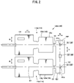
- Fig. 2 is a plan view of the terminal connection strip 100A after a blanking step
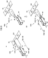
- Fig. 3 is a plan view of the terminal connection strip 100B after a bending step
- Fig. 4(a) to Fig. 4(c) are explanatory views of a welding step. This will be described in more detail.
- Fig. 4(a) shows a state where fiber laser welding is applied to the crimping base material 130B of the terminal connection strip 100B after the bending step
- both Fig. 4(b) and Fig. 4(c) are operation explanatory views showing a state where an intermediate portion of the crimping section 130 from a distal end side to a proximal end side of the crimping section 130 are welded
- Fig. 4(a) shows a state where fiber laser welding is applied to the crimping base material 130B of the terminal connection strip 100B after the bending step
- both Fig. 4(b) and Fig. 4(c) are operation explanatory
- FIG. 4(b) is a longitudinal cross-sectional view of the crimping base material 130B of the terminal connection strip 100B as viewed in the terminal width direction Wt
- Fig. 4(c) is a plan view of the crimping base material 130B of the terminal connection strip 100B and an area around the crimping base material 130B.
- FIG. 4(a) The illustration of a clamping jig 300 is omitted in Fig. 4(a) .
- Both Fig. 5(a1) and Fig. 5(a2) are operation explanatory views showing a state where a proximal end portion 130P2 of the crimping base material 130B is welded, wherein Fig. 5(a1) is a longitudinal cross-sectional view of the crimping base material 130B of the terminal connection strip 100B as viewed in the terminal width direction Wt, and Fig. 5(a2) is a plan view showing the crimping base material 130B of the terminal connection strip 100B and an area around the crimping base material 130B.
- Both Fig. 5(b1) and Fig. 5(b2) are operation explanatory views showing a state where a laser beam L is emitted to a connection portion 151 that connects a carrier 150, the laser beam L having passed a proximal end portion 130P2 of the crimping section 130C, wherein Fig. 5(b1) is a longitudinal cross-sectional view of the crimping base material 130C of the terminal connection strip 100C as viewed in the terminal width direction Wt, and Fig. 5(b2) is a plan view showing the crimping base material 130C of the terminal connection strip 100C and an area around the crimping base material 130C.
- the female crimp terminal 110 can be manufactured by performing a blanking step, a bending step, a welding step, a sealing portion forming step, and a separating step in this order.
- the blanking step is a step where the terminal connection strip 100A is blanked from a base material.
- the terminal connection strip 100A is a plate-shaped base material for forming the female crimp terminal 110, and is a copper alloy strip made of brass or the like (not shown in the drawing) and having a surface thereof plated with tin (Sn plating).
- the terminal connection strip 100A is blanked from the base material into a strip shape where a plurality of terminal fittings 110A are projected from one end of the carrier 150 in the carrier width direction Wc by way of connection portions 151 at fixed intervals.
- the terminal fitting 110A has a terminal shape obtained by developing the female crimp terminal 110 in plane, and a crimping base material 130A corresponding to the crimping section 130 in a pre-crimping state includes barrel members 130z extending from both sides of a crimping base material 130A in the terminal width direction Wt.
- the terminal fitting 110A in a planar state is bent so that the terminal fitting 110A is formed into a stereoscopic shape.
- the terminal fitting 110A is bent into a stereoscopic terminal shape consisting of a box section 120 formed of a hollow quadrangular columnar body and a crimping section 130B having an approximately circular shape as viewed from a rear side.
- the crimping base material 130A is bent in a cylindrical shape such that the opposedly-facing edge portions 130t of the crimping base material 130A which face each other in an opposed manner in the circumferential direction face each other in an opposed manner at the place which is not disposed on the same plane as a carrier surface 150F of the carrier 150, at least the conductor tip 201a can be inserted into the crimping section 130B from a proximal end side of the crimping section 130B, and the crimping base material 130A can surround the conductor tip 201a.
- the welding step is a step where a crimping section 130B of the terminal fitting 110B corresponding to the crimping section 130 which is connected to the wire tip 200a of the insulated wire 200 by crimping is bent around an axis of the terminal fitting 110B, the opposedly-facing edge portions 130t which face each other in an opposed manner are welded to each other by a laser beam L thus forming a cylindrical crimping section 130C.
- the opposedly-facing edge portions 130t are welded to each other by a laser beam while making the opposedly-facing edge portions 130t move along the terminal long length direction Lt of the crimping section 130B (long length direction welding step).
- the welding is applied to the opposedly-facing edge portions 130t of the crimping base material 130A which is bent in the bending step such that the opposedly-facing edge portions 130t face each other in an opposed manner at the place which is not disposed on the same plane as the carrier surface 150F of the carrier 150. Accordingly, the welded portion 141 can be formed at the place which is not disposed on the same plane as the carrier surface 150F of the carrier 150.
- the terminal fitting 110B is positioned by a clamping jig 300 constituted of a clamping jig body 310 which fixes the terminal fitting 110B and a positioning portion 320 which performs the positioning of the terminal fitting 110B.
- the clamping jig body 310 is formed in an elongated manner along the terminal long length direction Lt so as to cover an upper portion of the terminal fitting 110B.
- a slit 311 is formed in the clamping jig body 310 along the terminal long length direction Lt so as to allow a laser beam L to be emitted to the opposedly-facing edge portions 130t of the terminal fitting 110B.
- the positioning portion 320 is positioned on a proximal end side of the clamping jig body 310 above the carrier 150. A position of the terminal fitting 110B and a position of the clamping jig 300 are fixed by inserting a positioning jig pin 321 of the positioning portion 320 which extends downward into a positioning hole 160 formed in the carrier 150.
- the sealing portion forming step is a step where a distal end side of the crimping section 130C is compressed by a crimper and an anvil not shown in the drawing until a portion of the crimping section 130C on a distal end side from the wire crimping section 131 is sealed.
- Sealing property of the sealing portion 132 may be enhanced by applying welding to the sealing portion 132 while sliding the fiber laser welding device Fw along the terminal width direction Wt of the sealing portion 132 after the sealing portion forming step.
- the terminal fitting 110D is separated from the carrier 150 by cutting the connection portion 151 or the like.
- connection portion 151 In cutting the connection portion 151 in the carrier separating step, it is desirable to cut the connection portion 151 such that the connection portion 151 slightly remains on the crimping base material 130C from a boundary between the crimping base material 130C and the connection portion 151.
- a specific position of a cut portion is at a position on the connection portion 151 away from the boundary between the crimping base material 130C and the connection portion 151 by a length of the remaining connection portion 151, that is, 0.1 to 0.2 mm.
- the female crimp terminal 110 can be manufactured using the terminal connection strip 100.
- the wire tip 200a is inserted into the wire crimping section 131 of the crimping section 130.
- a cover tip 202a of the wire tip 200a is inserted into the inside of the wire crimping section 131a from a rear side of the crimping section 130, and a conductor tip 201a of the wire tip 200a is inserted into the inside of the conductor crimping section 131b.
- the female crimp terminal 110 can be connected to the wire tip 200a by crimping. Due to such operations, a crimp-terminal-equipped wire can be manufactured.
- the crimping section 130 of the female crimp terminal 110 and the wire tip 200a are not necessarily connected to each other by crimping after the separating step where the terminal fitting 110D is separated from the carrier 150.
- the wire tip 200a may be connected by crimping to the terminal fitting 110D which is integrally connected to the carrier 150.
- the carrier separating step may be performed simultaneously with the crimping connection step where the crimping section 130 of the female crimp terminal 110 and the wire tip 200a are connected to each other by crimping, or may be performed after the crimping connection step.
- proximal end portion 130P2 of the welded portion 141 in the terminal long length direction Lt is formed at a portion upwardly spaced apart from the carrier 150 by an amount corresponding to a diameter of the crimping section 130 such that the proximal end portion 130P2 is not disposed on the same plane as the carrier surface 150F of the carrier 150 in the circumferential direction of the crimping section 130C.
- the fiber laser welding device Fw is moved along the terminal long length direction Lt of the crimping base material 130B while emitting the laser beam L to the opposedly-facing edge portions 130t from the fiber laser welding device Fw.
- the fiber laser welding device Fw In the case of emitting the laser beam L to the opposedly-facing edge portions 130t, when the fiber laser welding device Fw reaches the proximal end portion 130P2 of the crimping section 130 in the terminal long length direction Lt as shown in Fig. 5(a1) and Fig. 5(a2) and, thereafter, passes the proximal end portion 130P2 and reaches the connection portion 151 between the carrier 150 and the terminal fitting 110C as shown in Fig. 5(b1) and Fig. 5(b2) , the fiber laser welding device Fw emits the laser beam L to the connection portion 151.
- At least the proximal end portion 130P2 of the welded portion 141 in the terminal long length direction Lt is formed at the place which is not disposed on the same plane as the carrier surface 150F of the carrier 150 in the circumferential direction of the crimping section 130C. Due to such a constitution, particularly, as shown in Fig. 5(b1) , a focal point Lp of heat emitted from the fiber laser welding device Fw is displaced from the connection portion 151 (carrier surface 150F).
- a distance from a laser beam emitting portion Fw1 of the fiber laser welding device Fw to the carrier surface 150F is larger than a distance from the laser beam emitting portion Fw1 to the opposedly-facing edge portions 130t of the crimping section 130. Accordingly, the laser beam L is emitted such that a focal point of the laser beam L is on the opposedly-facing edge portions 130t of the crimping section 130, and a focal point Lp of the laser beam L is not on the carrier surface 150F.
- connection portion 151 even when the laser beam L passes through the proximal end portion 130P2 of the welded portion 141 in the terminal long length direction Lt, and is emitted to the connection portion 151 between the terminal fitting 110C and the carrier 150, a damage which is given to the connection portion 151 or the carrier 150 can be decreased so that there is no possibility that the connection portion 151 is unexpectedly melted or that a cut portion is formed on the connection portion 151. Accordingly, it is possible to maintain reliability of the connection portion 151 where the crimping base material 130C and the carrier 150 are connected to each other.
- connection portion 151 is unexpectedly separated before the wire tip 200a is crimped to the crimping section 130.
- connection portion 151 it is possible to prevent the connection portion 151 from being unexpectedly separated in welding the opposedly-facing edge portions 130t of the crimping section 130C by the laser beam L and hence, as shown in Fig. 5(a1) and Fig. 5(a2) , the opposedly-facing edge portions 130t of the crimping section 130C can be surely welded to each other up to the proximal end portion 130P2 of the crimping section 130C in the terminal long length direction Lt.
- the crimping section 130 can be accurately formed into a hollow shape and hence, it is possible to form a high-quality crimp terminal provided with a hollow crimping section 130 having excellent water-blocking performance and excellent conductivity.
- the crimping section 130 of each terminal fitting 110D can be surely formed into a hollow shape by welding and hence, it is possible to efficiently manufacture high-quality female crimp terminals 110 on a mass production basis.
- Positioning holes 160 (first positioning holes 161) each of which allows the insertion of a positioning pin which performs the positioning of the carrier 150 are formed in the carrier 150 of the terminal connection strip 100 along the carrier long length direction Lc.
- the positioning hole 160 is provided for each connection portion 151 which connects the terminal fitting 110D to the carrier 150. This will be described in more detail.
- the positioning holes 160 are formed in the carrier 150 on a center axis CL1 in the terminal width direction Wt.
- the carrier 150 by sliding the carrier 150 along the carrier long length direction Lc in a state where the positioning pin is inserted into the positioning hole 160, the carrier 150 can be fed at fixed intervals.
- the crimping section 130A of the terminal fitting 110A is bent about the axis of the terminal fitting and the opposedly-facing edge portions 130t which face each other in an opposed manner are welded to each other. Accordingly, in emitting a laser beam L along the terminal long length direction Lt of the crimping section 130B by the fiber laser welding device Fw, by using a center 161a of the positioning hole 160 positioned on an extension line of the opposedly-facing edge portion 130t as a target, it is possible to allow the fiber laser welding device Fw to accurately emit the laser beam L to the opposedly-facing edge portions 130t without displacing an emitting position in the terminal width direction Wt.
- a rear side (proximal end side) of the crimping section 130 is connected to the carrier 150 by way of the connection portion 151 and hence, the wire tip 200a can be easily inserted into the crimping section 130, and it is also possible to reduce a material cost of a base material for forming the terminal connection strip 100.
- a resilient contact lug 121 which projects to a distal end side from the terminal fitting 110A and the carrier 150 are connected to each other by way of the connection portion 151.
- a connection portion 151 it is assumed that the box section 120 and the carrier 150 are connected to each other by way of a connection portion 151 longer than the resilient contact lug 121 at a position of the terminal fitting 110A displaced from the resilient contact lug 121 in the carrier long length direction Lc.
- connection portion 151 including the resilient contact lug 121 is elongated.
- the connection portion 151 is elongated in a single manner. Accordingly, the terminal fitting 110A in a cantilever manner with respect to the carrier 150 is easily deflected by own weight.
- the box section 120 side of the deflected terminal fitting 110D is connected to the carrier 150 and hence, even when a deflection amount of the terminal fitting 110D with respect to the carrier 150 is small, a displace amount of the crimping section 130 due to deflection is large on a rear side of the crimping section 130 into which the wire tip 200a is inserted. Accordingly, it becomes difficult to insert the wire tip 200a into the inside of the wire crimping section 131.
- a distance between the positioning hole 160 formed in the carrier 150 and the rear side of the crimping section 130 into which the wire tip 200a is inserted becomes long compared to a case where a crimping section 130 side of the terminal fitting 110A and the carrier 150 are connected to each other.
- the terminal connection strip 100 having the elongated connection portion 151 requires to blank an extra material in blanking the terminal connection strip 100 from the base material in the blanking step and hence, a material cost is pushed up.
- connection portion 151 when the resilient contact lug 121 projecting from the terminal fitting 110A to a distal end side and the carrier 150 are connected to each other by way of the connection portion 151, a boundary between a distal end portion of the resilient contact lug 121 of the terminal fitting 110A and the connection portion 151 is cut. Accordingly, there is a possibility that a burr is formed on the distal end portion of the resilient contact lug 121 along with the cutting of the connection portion 151.
- connection portion 151 a rear side of the crimping section 130 into which the wire tip 200a is inserted and the carrier 150 are connected to each other by way of the connection portion 151. Accordingly, it is possible to set a length of the connection portion 151 to a necessary minimum length.
- a length of the connection portion 151 can be shortened and, at the same time, a distance between the positioning hole 160 formed in the carrier 150 and the rear side of the crimping section 130 into which the wire tip 200a is inserted is shortened and hence, a deformation amount of the crimping section 130 on the rear side of the crimping section 130 along with the deflection or rotation of the terminal fitting 110A can be suppressed to a minimum amount so that the wire tip 200a can be easily inserted into the crimping section 130.
- the female crimp terminal 110 can maintain favorable electrical connection performance with a male crimp terminal not shown in the drawing.
- connection portion 151 can be set to a necessary minimum length and hence, a material cost can be lowered.
- the female crimp terminal 110 of this embodiment it is possible to accurately and efficiently manufacture a closed-barrel-type female crimp terminal 110 provided with the crimping section 130 formed into a hollow shape.
- a closed-barrel-type crimp terminal is manufactured by molding or brazing one by one individually.
- each of the terminal fittings 110A, 110B, 110C, 110D provided to the terminal connection strip 100 can be accurately positioned with respect to the predetermined processing positions while conveying the terminal connection strip 100 to a downstream side in the processing direction.
- the opposedly-facing edge portions 130t which are made to abut against each other by bending a portion of the terminal fitting 110B corresponding to the crimping section 130B about an axis of the terminal fitting are welded by the fiber laser beam L thus forming the cylindrical crimping section 130C.
- an extremely small spot can be set as a focal point in the fiber laser welding and hence, it is possible to realize laser welding with high output and, at the same time, a laser beam can be emitted in a continuous manner.
- the opposedly-facing edge portions 130t of the crimping section 130B can be accurately welded to each other.
- the terminal connection strip 100 having the positioning holes 160 is used and, at the same time, the closed-barrel-type female crimp terminal 110 is manufactured using the fiber laser welding device Fw and hence, it is possible to manufacture the high-quality closed-barrel-type female crimp terminals 110 each provided with a crimping section 130 formed into a hollow shape with no gap on a mass production basis.
- a positioning hole 160 for every predetermined number of positioning holes 160 may have a hole shape different from a hole shape of other positioning holes 160.
- the plurality of first positioning holes 161 are formed in the carrier 150 along the carrier long length direction Lc. Out of the plurality of first positioning holes 161, the first positioning hole 161 arranged for every predetermined number of first positioning holes 161 in the carrier long length direction Lc has a shape different from a hole shape of other first positioning holes 161.
- the first positioning hole 161 for every predetermined number of first positioning holes 161 is formed into a hole shape different from the perfect circular shape.
- the first positioning hole 161 having a different hole shape is set as a different-shaped first positioning hole 161s.
- the different-shaped first positioning hole 161s has a cut-away portion 161x which is formed by cutting away a portion of a hole having a perfect circular shape in the circumferential direction.
- the female crimp terminals 110 may be manufactured by applying working to a plurality of respective terminal fittings 110D which are connected to each other in the carrier long length direction Lc in a chained manner one by one while sequentially feeding the carrier 150.
- the manufacture of the female crimp terminals 110 is not limited to such a manufacturing method.
- a plurality of female crimp terminals 110 may be collectively manufactured in such a manner that a plurality of terminal fittings (a group of terminal fittings) 110D are set as one lot, and working is applied to the plurality of terminal fittings (a group of terminal fittings) 110D simultaneously in a collective manner on a lot-by-lot basis while feeding the carrier 150.
- the plurality of female crimp terminals 110 can be collectively manufactured by simultaneously applying working to a group of terminal fittings on a lot-by-lot basis while feeding the carrier 150 in a state where the positioning pin is inserted for every different-shaped first positioning hole 161s arranged in the carrier long length direction Lc.
- the different-shaped first positioning hole 161s is formed for every predetermined number of terminal fittings 110D included in each group of terminal fittings which constitute one lot. If it is possible to identify a lot in which a defect occurs, the position of a different-shaped first positioning hole 161s corresponding to the lot can be identified in the carrier long length direction Lc. By identifying the position of the different-shaped first positioning hole 161s in this manner, terminal fittings 110D included in the lot can be easily allocated so that the certain terminal fitting 110D in which the defect occurs can be easily and surely identified.
- the plurality of female crimp terminals 110 can be efficiently manufactured in a continuous manner from the plurality of terminal base materials 110A connected in a chain state in the carrier long length direction Lc on the mass production basis.
- a shape of the first positioning hole 161, a shape of the different-shaped first positioning hole 161s, and a shape of the second positioning hole 162 are not limited to the above-mentioned shapes, and may be other shapes.
- the terminal connection strip of the present invention adopts the constitution where, at least on the proximal end side of the crimping section 130 in the terminal long length direction Lt, the welded portion 141 is formed at the place which is not disposed on the same plane as the carrier surface 150F of the carrier 150 in the circumferential direction of the crimping section 130, the constitution of the terminal connection strip is not limited to the above-mentioned terminal connection strip 100, and the terminal connection strip may adopt a constitution of another embodiment.
- the terminal connection strip may include a terminal fitting 110Pa provided with a sealing portion 132 having a shape deformed in the thickness direction by compression on a distal end side of the crimping section 130 such that a base material faces each other on an upper surface side of the terminal fitting 110Pa.
- the terminal connection strip may include a terminal fitting 110Pb where a box section 120 and a crimping section 130 are formed separately, and the box section 120 and the crimping section 130 are integrally connected to each other at a transition section 140 as shown in Fig. 8(b2) .
- the welded portion 141 is formed at the place which is not disposed on the same plane as a carrier surface 150F of the carrier 150. Accordingly, in the same manner as the above-mentioned terminal connection strip 100, it is possible to acquire the advantageous effect that the high-quality crimp terminal provided with the hollow crimping section 130 can be manufactured efficiently and, at the same time, the crimping section 130 can be crimped to the conductor tip 201a in a crimped state with excellent water-blocking performance and excellent conductivity.
- the pair of opposedly-facing edge portions 130t is welded to each other while sliding the fiber laser welding device Fw along the terminal long length direction Lt from the distal end portion 130P1 (box section 120 side) of the crimping section 130B to a proximal end portion 130P2 (carrier 150 side) of the crimping section 130B thus forming the welded portion 141 at the opposedly-facing edge portion 130t (see Fig. 4(a) to Fig. 4(c) ).
- a welding method and the constitution are not limited to such a welding method and constitution.
- the method of welding is not limited to that the fiber laser welding device Fw is moved along the terminal long length direction Lt of the crimping section 130B. At least one of the fiber laser welding device Fw and the terminal fitting 110B may be moved such that a laser beam L emitted from the fiber laser welding device Fw is emitted to the opposedly-facing edge portions 130t of the crimping section 130B along the terminal long length direction Lt.
- the method of welding is not limited to that the opposedly-facing edge portions 130t of the crimping section 130B are welded to each other while moving at least one of the fiber laser welding device Fw and the terminal fitting 110B.
- the fiber laser welding may be performed using a mirror called a galvano mirror not shown in the drawing.
- the galvano mirror is a mirror which reflects a laser beam for scanning and, at the same time, is rotated by an amount corresponding to a level of an inputted drive voltage for allowing the laser beam to be polarized at a reflection angle of a desired angle.
- the opposedly-facing edge portions 130t can be surely welded.
- connection portion 151 Even when the laser beam L passes the proximal end portion 130P2 of the crimping section 130B due to the oscillation angle of the galvano mirror and is emitted to the connection portion 151, a focal point Lp of the laser beam L emitted from the fiber laser welding device Fw is not on the connection portion 151 (carrier surface 150F). Accordingly, there is no possibility that the connection portion 151 is unexpectedly melt or a cut portion is formed on the connection portion 151 and hence, the welded portion 141 can be accurately formed on the opposedly-facing edge portions 130t of the crimping section 130B.
- the terminal connection strip may include a terminal fitting 110Pc provided with a crimping section 130D where an orthogonal cross section of the crimping section 130D which is taken along a line orthogonal to the terminal long length direction Lt has an elliptical circular shape.
- the crimping section 130D is formed into an elliptical circular shape having a long axis in the vertical direction in cross section.
- the wire tip 200a can be surely inserted into the inside of the crimping section 130D avoiding the interference with the carrier cutting device 340.
- the constitution of the carrier of the present invention is not limited to the constitution where the first positioning hole 161 and the second positioning hole 162 are formed in the carrier as the above-mentioned positioning hole 160, wherein the first positioning hole 161 and the second positioning hole 162 are used at the time of feeding the terminal connection strip 100 along the carrier long length direction Lc by allowing the insertion of the positioning pin which a carrier feeding mechanism not shown in the drawing includes.
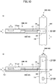
- the carrier may adopt the constitution shown in Fig. 10(a) where only the first positioning holes 161 are formed in the carrier, or the constitution shown in Fig. 10(b) where only the second positioning holes 162 are formed on the carrier.
- the first positioning hole 161 is arranged at a position on the terminal long length direction Lt of the welded portion 141 of the terminal fitting 110B, that is, on an extension line of the welded portion 141. Accordingly, a distance from a positioning jig pin 321 inserted into the first positioning hole 161 to the terminal fitting 110B can be set to a minimum distance and hence, the clamping jig 300 can be small sized.
- a moving amount (stroke amount) of the clamping jig 300 or the like can be set to a minimum value and hence, an operation time in the welding step can be shortened.
- the constitution of the positioning holes 160 can be suitably set according to a specification of the female crimp terminal 110 to be manufactured, manufacturing conditions or the like. That is, the positioning holes 160 may be formed only of the first positioning holes 161 or formed only of the second positioning holes 162. Alternatively, the positioning holes 160 may be formed by both the first positioning holes 161 and the second positioning holes 162.
- a shape of the cover crimping section 131a and a shape of the conductor crimping section 131b of the present invention are not limited to cylindrical shapes having a substantially equal diameter.
- the crimping section 130 may be formed into a so-called bellmouth shape where a diameter of a proximal end portion of the cover crimping section is increased compared to other portions of the cover crimping section for allowing the conductor crimping section to have a diameter narrower than a diameter of the cover crimping section.
- the crimping section 130 may be formed such that the cover crimping section and the conductor crimping section have different diameters by forming a stepped portion at a boundary portion between the cover crimping section 1310a and the conductor crimping section 1310b.
- Fig. 11(a) is a perspective view of the female crimp terminal 1100
- Fig. 11(b) is a longitudinal cross-sectional view describing a state after the wire inserting step
- Fig. 11(c) is a longitudinal cross-sectional view describing a state after the crimping connection step.
- the proximal end portion of the cover crimping section When the proximal end portion of the cover crimping section is formed into a bellmouth shape, it is possible to prevent the state where a rear end portion of the cover crimping section bites into the insulating cover 202 in a post-crimping state with the wire tip 200a thus damaging the insulating cover 202. Accordingly, the high-quality crimp-terminal-equipped wire (not shown in the drawing) can be formed.
- a deformation amount of the conductor crimping section 1310b at the time of crimping the conductor crimping section 1310b to the wire tip 200a can be reduced compared to the conductor crimping section 131b of the wire crimping section 131 where a stepped portion is not formed at a boundary portion.
- an inner diameter of the cover crimping section 1310a is set substantially equal to or slightly larger than an outer diameter of the cover tip 202a and, at the same time, an inner diameter of the conductor crimping section 1310b is set substantially equal to or slightly larger than an outer diameter of the conductor tip 201a.
- the stepped portion 1310x of the wire crimping section 1310 where the cover crimping section 1310a and the conductor crimping section 1310b are formed in a stepwise manner is not formed into a stepped shape which is orthogonal to the terminal long length direction Lt, but is formed into a stepped shape gradually and smoothly lowered from the cover crimping section 1310a to the conductor crimping section 1310b.
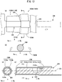
- Fig. 12(a) is a plan view showing a state where the core rod 330 is placed on a crimping base material 1300A
- Fig. 12(b) is a cross-sectional view taken along line B-B in Fig. 12(a)
- Fig. 12(c) is a longitudinal cross-sectional view showing a state where the crimping section 1300 is formed into a hollow shape
- Fig. 12(d) is a cross-sectional view taken along line C-C in Fig. 12(c) .
- a terminal base material is blanked into a shape obtained by developing the hollow crimping section 1300 formed into a stepped shape in plane.
- the core rod 330 is placed on the terminal base material such that, as shown in Fig. 12(a) , a stepped portion 332 of the core rod 330 is positioned at a stepped portion corresponding portion 1310y which corresponds to a stepped portion 1310x of the wire crimping section 1310.
- both end portions of the crimping base material 1300A in the terminal width direction Wt are bent about the core rod axis 331 and, as shown in Fig. 12(c) and Fig. 12(d) , the crimping base material 1300A is formed into a hollow shape which surrounds the core rod 330 by a press die not shown in the drawing.
- Fig. 13 is a cross-sectional view of the conductor crimping section 1310b and the conductor tip 201a in a state where the conductor crimping section 1310b and the conductor tip 201a are connected to each other by crimping with the wire crimping section 1310 formed into a stepped shape.
- Fig. 14 is a cross-sectional view of the conductor crimping section 131b and the conductor tip 201a in a state where the conductor crimping section 131b and the conductor tip 201a are connected to each other by crimping with the wire crimping section 131 not formed into a stepped shape.
- a deformation amount of the conductor crimping section 1310b at the time of crimping the conductor crimping section 1310b to the wire tip 200a can be reduced so that an amount of an excessively large thick wall portion generated at the conductor crimping section 1310b along with the crimping can be reduced.
- the cover crimping section 131a and the conductor crimping section 131b are formed into cylindrical shapes having a substantially equal diameter, that is, the cover crimping section 131a and the conductor crimping section 131b are not formed into a stepped manner.
- an amount of deformation along with the crimping is large in the conductor crimping section 131b crimped to the conductor tip 201a than in the cover crimping section 131a crimped to the cover tip 202a. Accordingly, an excessively large thick wall portion is generated at the conductor crimping section 131b.
- the excessively large thick wall portion generated at the conductor crimping section 131b forms an inwardly-falling portion 131z which projects in a falling manner toward the center of the wire crimping section 131 as shown in Fig. 14 .
- the inwardly-falling portion 131z serves as an obstacle when the conductor crimping section 131b and the conductor tip 201a are crimped to each other. Accordingly, as shown in an enlarged view in Fig. 14 , the conductor tip 201a does not reach a corner portion of the conductor crimping section 131b and hence, there exists a possibility that a gap is generated between the conductor crimping section 131b and the conductor tip 201a.
- the wire crimping section 131 where the gap is generated between the conductor crimping section 131b and the conductor tip 201a has, in a state where the conductor crimping section 131b and the conductor tip 201a are connected to each other by crimping, the deteriorated electrical connection or the moisture intrusion due to the capillarity. Accordingly, such a wire crimping section 131 has deteriorated electrical characteristics.
- a gap formed between the conductor crimping section 1310b and the conductor tip 201a becomes smaller than a gap formed between the conductor crimping section 131b and the conductor tip 201a in the case where the boundary portion between the cover crimping section 131a and the conductor crimping section 131b is not formed into a stepped shape.
- an amount of deformation of the conductor crimping section 1310b along with the crimping can be decreased so that the generation of the excessively large thick wall portion can be suppressed. Accordingly, the generation of the inwardly-falling portion at the conductor crimping section 1310b can be prevented so that the conductor crimping section 1310b and the conductor tip 201a can be closely connected to each other by crimping.
- the stepped portion 1310x of the wire crimping section 1310 is formed into a stepped shape which is gradually and smoothly lowered from the cover crimping section 1310a to the conductor crimping section 1310b. Accordingly, the wire tip 200a can be easily inserted into the wire crimping section 1310.
- the female crimp terminal 1100 is manufactured using the core rod 330. Accordingly, even when the female crimp terminals 1100 are manufactured on a mass production basis, there is no possibility that a position of the stepped portion 1310x of the wire crimping section 1310 is changed for every female crimp terminal 1100. That is, the stepped portion 1310x of the wire crimping section 1310 can be formed at a desired position.
- the conductor crimping section is formed with a length larger than a desired length in the terminal long length direction Lt.
- an inner diameter of the cover crimping section 1310a is set substantially equal to or slightly larger than an outer diameter of the cover tip 202a
- an inner diameter of the conductor crimping section 1310b is set substantially equal to or slightly larger than an outer diameter of the conductor tip 201a as described above
- the cover tip 202a may be caught by the stepped portion of the wire crimping section at the time of inserting the wire tip 200a into the wire crimping section. Accordingly, there exists a possibility that the wire tip 200a cannot be firmly inserted into the wire crimping section.
- the cover crimping section is formed with a length larger than a desired length in the terminal long length direction Lt.
- the insertion of the wire tip 200a may be continued until the cover tip 202a is made to abut against the stepped portion of a crimping section body. Accordingly, there exists a possibility that the conductor tip 201a is bent.
- the cover crimping section is formed with a length larger than a desired length in the terminal long length direction Lt.
- a cover crimping section is positioned around the conductor tip 201a at the boundary portion between the conductor tip 201a and the cover tip 202a.
- a gap formed between the conductor tip 201a at the boundary portion between the conductor tip 201a and the cover tip 202a and the wire crimping section becomes larger than a gap formed between a distal end side of the conductor tip 201a and the wire crimping section. That is, the conductor crimping section in such a case has a possibility of forming an inwardly-falling portion at the time of connecting the conductor crimping section to the conductor tip 201a by crimping.
- the wire tip 200a can be inserted into the wire crimping section 1310 at a desired position without giving rise to a drawback that the insertion of the wire tip 200a into the wire crimping section 1310 is insufficient, a drawback that the distal end of the conductor tip 201a is bent, or a drawback that a gap formed between the conductor crimping section 1310b and the conductor tip 201a becomes large.
- the desired position is a position on the terminal long length direction Lt where the boundary portion between the conductor tip 201a and the cover tip 202a corresponds to the stepped portion 1310x of the wire crimping section 1310.
- the wire crimping section 1310 and the wire tip 200a can maintain a state where the wire crimping section 1310 and the wire tip 200a are closely connected to each other by crimping. Accordingly, it is possible to acquire a wire provided with a terminal having favorable electrical connection performance.
Landscapes
- Engineering & Computer Science (AREA)
- Manufacturing & Machinery (AREA)
- Manufacturing Of Electrical Connectors (AREA)
- Physics & Mathematics (AREA)
- Optics & Photonics (AREA)
- Connections Effected By Soldering, Adhesion, Or Permanent Deformation (AREA)
Claims (3)
- Anschlussleiste (100, 100A bis 100C, 100Pa bis 100Pc), umfassend:einen leistenförmig ausgebildeten Träger (150); undeine Vielzahl von Anschlusskontakten (110A bis 110D, 110Pa bis 110Pc), die von wenigstens einer Kantenseite des Trägers (150) in einer Trägerbreitenrichtung (Wc) vorstehen, wobeijeder der Anschlusskontakte (110A bis 110D, 110Pa bis 110Pc) einen Crimpteil (130, 130A bis 130D) beinhaltet,wobei jeder Crimpteil (130, 130A bis 130D) dafür eingerichtet ist, wenigstens eine Leiterspitze eines Drahtes aufzunehmen, wobei es sich bei der Leiterspitze um einen Abschnitt des Drahtes handelt, der durch Abziehen einer isolierenden Abdeckung des isolierten Drahtes an einer distalen Endseite freigelegt wird, wobei eine proximale Endseite des Crimpteils (130, 130A bis 130D) und der Träger (150) mithilfe eines Verbindungsabschnitts (151) miteinander verbunden sind,wobei jeder Crimpteil (130, 130A bis 130D) aus einem plattenförmigen Basismaterial gebildet ist, das Trommelelemente (130z) aufweist, die sich von beiden Seiten des Basismaterials in einer Anschlussbreitenrichtung (Wt) erstrecken,wobei die Anschlussbreitenrichtung (Wt) orthogonal zur Trägerbreitenrichtung (Wc) ist,dadurch gekennzeichnet, dassdie Trommelelemente (130z) anschließend gebogen werden, bis die Kantenabschnitte (130t) der Trommelelemente (130z) aneinander anstoßen, um eine hohlzylindrische Form zu bilden, wobei die beiden Kantenabschnitte (130t) anschließend miteinander verschweißt werden, um einen geschweißten Abschnitt (141) zu bilden, unddass wenigstens eine proximale Endseite des geschweißten Abschnitts (141) in der Anschlusslängsrichtung (Lt) an einer Stelle gebildet ist, die nicht auf der gleichen Ebene wie eine Trägeroberfläche (150F) des Trägers (150) angeordnet ist, unddass der Crimpteil (130, 130A bis 130D) aus einem durchgehenden integralen Körper gebildet ist, der aus einem Drahtcrimpteil (131) und einem Dichtungsabschnitt (132) besteht, die von einer proximalen Endseite zu einer distalen Endseite angeordnet sind, wobei die Abdichtung des Dichtungsabschnitts erfolgt, indem ein Abschnitt des Crimpabschnitts (130C) an einer distalen Endseite ausgehend von dem Drahtcrimpabschnitt (131) zusammengedrückt wird, woraus sich ergibt, dass jeder Crimpteil (130, 130A bis 130D) in einem gecrimpten Zustand eine wasserblockierende Leistung aufweist.
- Anschlussleiste (100, 100A bis 100C, 100Pa bis 100Pc) nach Anspruch 1, wobei der Verbindungsabschnitt (151) mit einer Breite ausgebildet ist, die 1/16 oder mehr und 1/4 oder weniger einer äußeren Umfangslänge des Crimpteils beträgt.
- Anschlussleiste (100, 100A bis 100C, 100Pa bis 100Pc) nach einem der Ansprüche 1 oder 2, wobei erste Positionierungslöcher (161) in dem Träger (150) entlang eines Mittelachsenabschnitts in der Trägerbreitenrichtung (Wc) gebildet sind und entlang der Trägerlängsrichtung (Lc) des Trägers (150) derart angeordnet sind, dass sich ein Mittelabschnitt (161a) jedes ersten Positionierungslochs an einem Schnittpunkt zwischen einer Mittelachse (CL2) in der Trägerbreitenrichtung (Wc) und einer Erstreckung einer Anschlussmittelachse (CL1) in der Anschlussbreitenrichtung (Wt) befindet, wobei jedes erste Positionierungsloch (161) in einer Draufsicht in einer Kreislochform ausgebildet ist und für jeden Verbindungsabschnitt (151) angeordnet ist und das Einsetzen eines Positionierungsstifts ermöglicht, der den Träger (150) positioniert, wobei zweite Positionierungslöcher (162) in vorbestimmten Abständen in der Trägerlängsrichtung (Lc) des Trägers (150) angeordnet sind, sodass jedes zweite Positionierungsloch (162) zwischen Verbindungsabschnitten (151) positioniert ist, die die Anschlusskontakte (110D) verbinden, und wobei die zweiten Positionierungslöcher (162) in einer Draufsicht in einer Vierecklochform ausgebildet sind.
Applications Claiming Priority (4)
| Application Number | Priority Date | Filing Date | Title |
|---|---|---|---|
| JP2013032843 | 2013-02-22 | ||
| JP2013033970 | 2013-02-23 | ||
| JP2013107737 | 2013-05-22 | ||
| PCT/JP2013/084406 WO2014129078A1 (ja) | 2013-02-22 | 2013-12-24 | 端子連結帯、圧着端子の製造方法、電線圧着装置、及び電線圧着方法 |
Publications (3)
| Publication Number | Publication Date |
|---|---|
| EP2960991A1 EP2960991A1 (de) | 2015-12-30 |
| EP2960991A4 EP2960991A4 (de) | 2017-03-08 |
| EP2960991B1 true EP2960991B1 (de) | 2022-06-08 |
Family
ID=51390889
Family Applications (1)
| Application Number | Title | Priority Date | Filing Date |
|---|---|---|---|
| EP13875763.8A Active EP2960991B1 (de) | 2013-02-22 | 2013-12-24 | Verbindungsband für anschlussklemme, verfahren zur herstellung einer gecrimpten anschlussklemme, drahtcrimpvorrichtung und drahtcrimpverfahren |
Country Status (6)
| Country | Link |
|---|---|
| US (2) | US9601840B2 (de) |
| EP (1) | EP2960991B1 (de) |
| JP (3) | JP5579341B1 (de) |
| KR (1) | KR101822954B1 (de) |
| CN (2) | CN105075018B (de) |
| WO (1) | WO2014129078A1 (de) |
Families Citing this family (33)
| Publication number | Priority date | Publication date | Assignee | Title |
|---|---|---|---|---|
| US10574016B2 (en) * | 2011-03-13 | 2020-02-25 | Norman R BYRNE | Process for forming end product with initial and simultaneous formation of subcomponents from separate work pieces |
| WO2014129640A1 (ja) * | 2013-02-22 | 2014-08-28 | 古河電気工業株式会社 | 圧着端子の製造方法、圧着端子及びワイヤハーネス |
| FR3011691B1 (fr) * | 2013-10-04 | 2017-05-12 | Axon Cable Sa | Procede de fabrication de contact electrique, et contact electrique correspondant |
| US9859627B2 (en) * | 2016-04-26 | 2018-01-02 | Yazaki Corporation | Connection structure of terminal fitting and connection method of terminal fitting |
| KR20160149905A (ko) * | 2015-06-19 | 2016-12-28 | 에스케이하이닉스 주식회사 | 슬라이딩 접속 구조를 포함하는 반도체 패키지 |
| JP6322602B2 (ja) * | 2015-06-22 | 2018-05-09 | 日本オートマチックマシン株式会社 | 端子圧着アプリケータ、端子圧着機及び端子圧着電線の製造方法 |
| JP6506728B2 (ja) * | 2016-10-13 | 2019-04-24 | 矢崎総業株式会社 | 圧着端子および端子圧着装置 |
| JP6404295B2 (ja) * | 2016-10-13 | 2018-10-10 | 矢崎総業株式会社 | 端子圧着装置 |
| JP1583222S (de) * | 2016-12-13 | 2017-08-07 | ||
| JP1583221S (de) * | 2016-12-13 | 2017-08-07 | ||
| JP1583220S (de) * | 2016-12-13 | 2017-08-07 | ||
| JP1590185S (de) * | 2017-03-09 | 2017-11-06 | ||
| JP1590186S (de) * | 2017-03-09 | 2017-11-06 | ||
| JP1587159S (de) * | 2017-03-09 | 2017-10-02 | ||
| JP1587160S (de) * | 2017-03-09 | 2017-10-02 | ||
| FR3065330B1 (fr) * | 2017-04-13 | 2019-05-03 | Tyco Electronics France Sas | Outil pour souder un conducteur electrique avec un dispositif de connexion |
| JP6572936B2 (ja) * | 2017-05-10 | 2019-09-11 | 住友電装株式会社 | 端子圧着装置 |
| JP6556787B2 (ja) * | 2017-06-09 | 2019-08-07 | 矢崎総業株式会社 | 端子付き電線および端子圧着装置 |
| DE102017124693B3 (de) * | 2017-10-23 | 2018-11-29 | Lisa Dräxlmaier GmbH | Verfahren zum stoffschlüssigen Fügen einer elektrischen Leitung an ein elektrisches Kontaktteil |
| CN111295805A (zh) * | 2017-10-25 | 2020-06-16 | 株式会社自动网络技术研究所 | 线束部件 |
| JP2019144545A (ja) * | 2018-02-15 | 2019-08-29 | 株式会社川島製作所 | 端子付き導光体の製造方法、治具及び製造装置 |
| WO2019235389A1 (ja) * | 2018-06-05 | 2019-12-12 | 株式会社オートネットワーク技術研究所 | ジョイントコネクタ |
| FR3086875B1 (fr) * | 2018-10-05 | 2021-04-30 | Tyco Electronics France Sas | Dispositif pour souder un conducteur electrique avec un dispositif de connexion |
| JP7074080B2 (ja) * | 2019-01-15 | 2022-05-24 | 住友電装株式会社 | 端子付き電線 |
| JP2021034301A (ja) * | 2019-08-28 | 2021-03-01 | 株式会社オートネットワーク技術研究所 | 接続部品、接続部品付き電線、及びワイヤハーネス |
| CN111370971B (zh) * | 2020-03-24 | 2021-06-25 | 佛山市东信机械有限公司 | 一种电连接器接线端子的切断设备 |
| JP7435329B2 (ja) * | 2020-07-14 | 2024-02-21 | 住友電装株式会社 | 端子金具 |
| JP7402419B2 (ja) * | 2020-09-16 | 2023-12-21 | 住友電装株式会社 | 端子付き電線 |
| DE102021134299A1 (de) | 2021-12-22 | 2023-06-22 | Te Connectivity Germany Gmbh | Elektrischer Steckverbinder und Verfahren zum Montieren eines elektrischen Steckverbinders |
| CN114114577B (zh) * | 2022-01-21 | 2022-05-17 | 华海通信技术有限公司 | 一种海缆岸滩登入的光电分离装置 |
| CN116979340B (zh) * | 2023-08-03 | 2024-09-06 | 广州煜立光电科技有限公司 | 一种电连接端子的制作方法及该方法制成的电连接端子 |
| KR20250085426A (ko) * | 2023-12-05 | 2025-06-12 | 주식회사 엘지에너지솔루션 | 커넥터 핀 언폴딩 장치, 커넥터 핀 언폴딩 방법 및 커넥터 핀 분석 방법 |
| CN119009625B (zh) * | 2024-10-18 | 2025-01-24 | 常州协创智联电子有限公司 | 一种用于ccs电芯连接组件的加工设备 |
Family Cites Families (38)
| Publication number | Priority date | Publication date | Assignee | Title |
|---|---|---|---|---|
| US3473219A (en) * | 1967-07-10 | 1969-10-21 | Artos Engineering Co | Art of producing electrical terminals |
| US3516157A (en) * | 1967-09-08 | 1970-06-23 | Western Electric Co | Methods of and apparatus for assembling terminal strips |
| US3795889A (en) * | 1972-06-05 | 1974-03-05 | Amp Inc | Pin and socket type electrical contact terminals |
| US3857995A (en) * | 1972-11-24 | 1974-12-31 | Amp Inc | Electrical connector |
| US3864008A (en) * | 1973-08-07 | 1975-02-04 | Du Pont | Lead wire assembly |
| US4466689A (en) * | 1982-04-02 | 1984-08-21 | At&T Technologies, Inc. | Methods of making a terminal and products produced thereby |
| JPS60187480U (ja) | 1984-05-23 | 1985-12-12 | 株式会社 ニチフ端子工業 | 連続圧着端子 |
| JPH0235196U (de) | 1988-08-31 | 1990-03-07 | ||
| JPH0381083A (ja) | 1989-08-23 | 1991-04-05 | Amada Co Ltd | 熱切断加工機における加工ヘッド |
| JPH0381983A (ja) * | 1989-08-24 | 1991-04-08 | Nippon Chemicon Corp | 電子部品の製造方法および製造装置 |
| US5067916A (en) * | 1990-10-12 | 1991-11-26 | Amp Incorporated | Method for making an electrical contact |
| JPH06302341A (ja) | 1993-04-16 | 1994-10-28 | Yazaki Corp | レーザ溶接構造及びレーザ溶接端子 |
| US5340337A (en) * | 1993-06-04 | 1994-08-23 | The Whitaker Corporation | Protective sleeve for cantilevered spring contacts and method of making the same |
| JP2604338Y2 (ja) | 1993-10-26 | 2000-05-08 | 日本オートマチックマシン株式会社 | 端子圧着装置 |
| JP3318175B2 (ja) * | 1995-12-12 | 2002-08-26 | 矢崎総業株式会社 | 線材の接合方法 |
| JPH10328862A (ja) * | 1997-06-05 | 1998-12-15 | Harness Sogo Gijutsu Kenkyusho:Kk | レーザ溶接方法 |
| JP2002343529A (ja) * | 2001-05-21 | 2002-11-29 | Smk Corp | 横連鎖状端子の切断・加締め装置 |
| JP3994822B2 (ja) * | 2002-08-08 | 2007-10-24 | 住友電装株式会社 | 自動車用アース端子と電線の防水接続構造 |
| CN2561131Y (zh) * | 2002-08-08 | 2003-07-16 | 田正任 | 薄状电路片与端子之压着装置 |
| CN1266805C (zh) * | 2002-11-23 | 2006-07-26 | 富士康(昆山)电脑接插件有限公司 | 线缆连接器组件及其制造方法 |
| JP3982480B2 (ja) * | 2003-10-31 | 2007-09-26 | 住友電装株式会社 | マルチ圧着装置及び端子供給モジュール |
| US20050109501A1 (en) * | 2003-11-26 | 2005-05-26 | Ludwig Wesley N. | Perforating gun with improved carrier strip |
| CN2701110Y (zh) * | 2004-04-05 | 2005-05-18 | 黎木德 | 具铣沟槽体的导线端子压著部结构 |
| JP2006260978A (ja) * | 2005-03-17 | 2006-09-28 | Sumitomo Wiring Syst Ltd | 連鎖端子 |
| WO2008087938A1 (ja) * | 2007-01-16 | 2008-07-24 | Japan Automatic Machine Co., Ltd. | 端子圧着方法、端子圧着装置及び端子圧着電線製造装置 |
| JP4676452B2 (ja) * | 2007-03-19 | 2011-04-27 | 古河電気工業株式会社 | 端子付き電線の製造方法及び端子圧着部材 |
| JP5094604B2 (ja) * | 2008-07-14 | 2012-12-12 | 矢崎総業株式会社 | インナーターミナル |
| JP2010055874A (ja) * | 2008-08-27 | 2010-03-11 | Sumitomo Wiring Syst Ltd | 端子金具と電線の接続構造 |
| US20100105256A1 (en) * | 2008-10-28 | 2010-04-29 | Tektronix, Inc. | Electrical Contact Assembly and Method of Manufacture |
| JP5394713B2 (ja) * | 2008-12-10 | 2014-01-22 | 矢崎総業株式会社 | 圧着端子 |
| CN101888024B (zh) * | 2009-05-14 | 2012-11-28 | 富士康(昆山)电脑接插件有限公司 | 线缆连接器组件及其制造方法、导电端子及其料带 |
| US8083554B2 (en) * | 2009-06-05 | 2011-12-27 | Tyco Electronics Corporation | Connector assembly having a unitary housing |
| JP5430274B2 (ja) * | 2009-07-31 | 2014-02-26 | 矢崎総業株式会社 | 連鎖端子 |
| JP2011096452A (ja) * | 2009-10-28 | 2011-05-12 | Yazaki Corp | 圧着端子 |
| US8506336B2 (en) * | 2011-09-02 | 2013-08-13 | Tyco Electronics Corporation | Stamped and formed contact |
| CN102394410A (zh) * | 2011-09-28 | 2012-03-28 | 深圳市智泰电子有限公司 | 带线材电源连接器制造方法及其制品 |
| KR101428965B1 (ko) * | 2012-07-27 | 2014-09-03 | 후루카와 덴키 고교 가부시키가이샤 | 단자, 단자의 제조 방법 및 전선의 종단 접속 구조체 |
| KR101490095B1 (ko) * | 2013-02-23 | 2015-02-04 | 후루카와 덴키 고교 가부시키가이샤 | 단자, 전선 접속 구조체 및 단자의 제조방법 |
-
2013
- 2013-12-24 JP JP2014506650A patent/JP5579341B1/ja active Active
- 2013-12-24 EP EP13875763.8A patent/EP2960991B1/de active Active
- 2013-12-24 CN CN201380073684.1A patent/CN105075018B/zh active Active
- 2013-12-24 KR KR1020157024324A patent/KR101822954B1/ko active Active
- 2013-12-24 CN CN201810336566.XA patent/CN108565563B/zh active Active
- 2013-12-24 WO PCT/JP2013/084406 patent/WO2014129078A1/ja not_active Ceased
-
2014
- 2014-05-19 JP JP2014103447A patent/JP5598887B1/ja active Active
- 2014-07-25 JP JP2014151581A patent/JP6210557B2/ja active Active
-
2015
- 2015-08-21 US US14/832,894 patent/US9601840B2/en active Active
-
2017
- 2017-02-07 US US15/426,814 patent/US10424891B2/en active Active
Also Published As
| Publication number | Publication date |
|---|---|
| US20150364838A1 (en) | 2015-12-17 |
| US10424891B2 (en) | 2019-09-24 |
| JP5598887B1 (ja) | 2014-10-01 |
| CN105075018A (zh) | 2015-11-18 |
| KR20150120407A (ko) | 2015-10-27 |
| CN108565563B (zh) | 2020-05-08 |
| CN105075018B (zh) | 2018-05-08 |
| JP2015005500A (ja) | 2015-01-08 |
| KR101822954B1 (ko) | 2018-01-29 |
| EP2960991A4 (de) | 2017-03-08 |
| CN108565563A (zh) | 2018-09-21 |
| US20170149192A1 (en) | 2017-05-25 |
| JPWO2014129078A1 (ja) | 2017-02-02 |
| JP6210557B2 (ja) | 2017-10-11 |
| US9601840B2 (en) | 2017-03-21 |
| JP2015005521A (ja) | 2015-01-08 |
| WO2014129078A1 (ja) | 2014-08-28 |
| EP2960991A1 (de) | 2015-12-30 |
| JP5579341B1 (ja) | 2014-08-27 |
Similar Documents
| Publication | Publication Date | Title |
|---|---|---|
| EP2960991B1 (de) | Verbindungsband für anschlussklemme, verfahren zur herstellung einer gecrimpten anschlussklemme, drahtcrimpvorrichtung und drahtcrimpverfahren | |
| US9281574B2 (en) | Crimp terminal, connection structural body, connector, wire harness, method of manufacturing crimp terminal, and method of manufacturing connection structural body | |
| EP2871718B1 (de) | Druckfixierbarer anschluss, verbindungsstruktur und verbinder | |
| JP2015005521A5 (de) | ||
| US9564691B2 (en) | Method for manufacturing crimp terminal, crimp terminal, and wire harness | |
| JP5567236B1 (ja) | 圧着端子、圧着接続構造体及び圧着接続構造体の製造方法 | |
| CN104969415B (zh) | 压接端子、压接端子的制造方法、电线连接结构体和电线连接结构体的制造方法 | |
| JP5567237B1 (ja) | 圧着端子、圧着接続構造体及び圧着接続構造体の製造方法 | |
| EP2961011B1 (de) | Verpresste leiterklemme sowie herstellungsverfahren für verpresste leiterklemmen | |
| JP2015018816A (ja) | 端子金具 | |
| US10122095B2 (en) | Crimp terminal, connecting structure, manufacturing method of the crimp terminal, and laser welding method | |
| JP6200366B2 (ja) | 接続構造体、ワイヤーハーネス、及び接続構造体の製造方法 | |
| JP2014164835A (ja) | 電線圧着装置、及び電線接続構造体の製造方法 | |
| JP5535287B2 (ja) | 接続構造体の製造方法、接続構造体、コネクタ、ワイヤハーネス |
Legal Events
| Date | Code | Title | Description |
|---|---|---|---|
| PUAI | Public reference made under article 153(3) epc to a published international application that has entered the european phase |
Free format text: ORIGINAL CODE: 0009012 |
|
| 17P | Request for examination filed |
Effective date: 20150825 |
|
| AK | Designated contracting states |
Kind code of ref document: A1 Designated state(s): AL AT BE BG CH CY CZ DE DK EE ES FI FR GB GR HR HU IE IS IT LI LT LU LV MC MK MT NL NO PL PT RO RS SE SI SK SM TR |
|
| AX | Request for extension of the european patent |
Extension state: BA ME |
|
| DAX | Request for extension of the european patent (deleted) | ||
| A4 | Supplementary search report drawn up and despatched |
Effective date: 20170202 |
|
| RIC1 | Information provided on ipc code assigned before grant |
Ipc: H01R 43/16 20060101AFI20170127BHEP Ipc: H01R 4/18 20060101ALN20170127BHEP Ipc: H01R 43/048 20060101ALN20170127BHEP Ipc: H01R 4/20 20060101ALN20170127BHEP |
|
| STAA | Information on the status of an ep patent application or granted ep patent |
Free format text: STATUS: EXAMINATION IS IN PROGRESS |
|
| 17Q | First examination report despatched |
Effective date: 20190410 |
|
| REG | Reference to a national code |
Ref country code: DE Ref legal event code: R079 Ref document number: 602013081827 Country of ref document: DE Free format text: PREVIOUS MAIN CLASS: H01R0004180000 Ipc: H01R0043160000 |
|
| RIC1 | Information provided on ipc code assigned before grant |
Ipc: H01R 4/18 20060101ALN20211201BHEP Ipc: H01R 43/048 20060101ALN20211201BHEP Ipc: H01R 4/20 20060101ALN20211201BHEP Ipc: H01R 43/16 20060101AFI20211201BHEP |
|
| GRAP | Despatch of communication of intention to grant a patent |
Free format text: ORIGINAL CODE: EPIDOSNIGR1 |
|
| STAA | Information on the status of an ep patent application or granted ep patent |
Free format text: STATUS: GRANT OF PATENT IS INTENDED |
|
| RIC1 | Information provided on ipc code assigned before grant |
Ipc: H01R 4/18 20060101ALN20211213BHEP Ipc: H01R 43/048 20060101ALN20211213BHEP Ipc: H01R 4/20 20060101ALN20211213BHEP Ipc: H01R 43/16 20060101AFI20211213BHEP |
|
| INTG | Intention to grant announced |
Effective date: 20220114 |
|
| GRAS | Grant fee paid |
Free format text: ORIGINAL CODE: EPIDOSNIGR3 |
|
| GRAA | (expected) grant |
Free format text: ORIGINAL CODE: 0009210 |
|
| STAA | Information on the status of an ep patent application or granted ep patent |
Free format text: STATUS: THE PATENT HAS BEEN GRANTED |
|
| AK | Designated contracting states |
Kind code of ref document: B1 Designated state(s): AL AT BE BG CH CY CZ DE DK EE ES FI FR GB GR HR HU IE IS IT LI LT LU LV MC MK MT NL NO PL PT RO RS SE SI SK SM TR |
|
| REG | Reference to a national code |
Ref country code: GB Ref legal event code: FG4D |
|
| REG | Reference to a national code |
Ref country code: AT Ref legal event code: REF Ref document number: 1497567 Country of ref document: AT Kind code of ref document: T Effective date: 20220615 Ref country code: CH Ref legal event code: EP |
|
| REG | Reference to a national code |
Ref country code: DE Ref legal event code: R096 Ref document number: 602013081827 Country of ref document: DE |
|
| REG | Reference to a national code |
Ref country code: IE Ref legal event code: FG4D |
|
| REG | Reference to a national code |
Ref country code: LT Ref legal event code: MG9D |
|
| REG | Reference to a national code |
Ref country code: NL Ref legal event code: MP Effective date: 20220608 |
|
| PG25 | Lapsed in a contracting state [announced via postgrant information from national office to epo] |
Ref country code: SE Free format text: LAPSE BECAUSE OF FAILURE TO SUBMIT A TRANSLATION OF THE DESCRIPTION OR TO PAY THE FEE WITHIN THE PRESCRIBED TIME-LIMIT Effective date: 20220608 Ref country code: NO Free format text: LAPSE BECAUSE OF FAILURE TO SUBMIT A TRANSLATION OF THE DESCRIPTION OR TO PAY THE FEE WITHIN THE PRESCRIBED TIME-LIMIT Effective date: 20220908 Ref country code: LT Free format text: LAPSE BECAUSE OF FAILURE TO SUBMIT A TRANSLATION OF THE DESCRIPTION OR TO PAY THE FEE WITHIN THE PRESCRIBED TIME-LIMIT Effective date: 20220608 Ref country code: HR Free format text: LAPSE BECAUSE OF FAILURE TO SUBMIT A TRANSLATION OF THE DESCRIPTION OR TO PAY THE FEE WITHIN THE PRESCRIBED TIME-LIMIT Effective date: 20220608 Ref country code: GR Free format text: LAPSE BECAUSE OF FAILURE TO SUBMIT A TRANSLATION OF THE DESCRIPTION OR TO PAY THE FEE WITHIN THE PRESCRIBED TIME-LIMIT Effective date: 20220909 Ref country code: FI Free format text: LAPSE BECAUSE OF FAILURE TO SUBMIT A TRANSLATION OF THE DESCRIPTION OR TO PAY THE FEE WITHIN THE PRESCRIBED TIME-LIMIT Effective date: 20220608 Ref country code: ES Free format text: LAPSE BECAUSE OF FAILURE TO SUBMIT A TRANSLATION OF THE DESCRIPTION OR TO PAY THE FEE WITHIN THE PRESCRIBED TIME-LIMIT Effective date: 20220608 Ref country code: BG Free format text: LAPSE BECAUSE OF FAILURE TO SUBMIT A TRANSLATION OF THE DESCRIPTION OR TO PAY THE FEE WITHIN THE PRESCRIBED TIME-LIMIT Effective date: 20220908 |
|
| REG | Reference to a national code |
Ref country code: AT Ref legal event code: MK05 Ref document number: 1497567 Country of ref document: AT Kind code of ref document: T Effective date: 20220608 |
|
| PG25 | Lapsed in a contracting state [announced via postgrant information from national office to epo] |
Ref country code: RS Free format text: LAPSE BECAUSE OF FAILURE TO SUBMIT A TRANSLATION OF THE DESCRIPTION OR TO PAY THE FEE WITHIN THE PRESCRIBED TIME-LIMIT Effective date: 20220608 Ref country code: LV Free format text: LAPSE BECAUSE OF FAILURE TO SUBMIT A TRANSLATION OF THE DESCRIPTION OR TO PAY THE FEE WITHIN THE PRESCRIBED TIME-LIMIT Effective date: 20220608 |
|
| PG25 | Lapsed in a contracting state [announced via postgrant information from national office to epo] |
Ref country code: NL Free format text: LAPSE BECAUSE OF FAILURE TO SUBMIT A TRANSLATION OF THE DESCRIPTION OR TO PAY THE FEE WITHIN THE PRESCRIBED TIME-LIMIT Effective date: 20220608 |
|
| PG25 | Lapsed in a contracting state [announced via postgrant information from national office to epo] |
Ref country code: SM Free format text: LAPSE BECAUSE OF FAILURE TO SUBMIT A TRANSLATION OF THE DESCRIPTION OR TO PAY THE FEE WITHIN THE PRESCRIBED TIME-LIMIT Effective date: 20220608 Ref country code: SK Free format text: LAPSE BECAUSE OF FAILURE TO SUBMIT A TRANSLATION OF THE DESCRIPTION OR TO PAY THE FEE WITHIN THE PRESCRIBED TIME-LIMIT Effective date: 20220608 Ref country code: RO Free format text: LAPSE BECAUSE OF FAILURE TO SUBMIT A TRANSLATION OF THE DESCRIPTION OR TO PAY THE FEE WITHIN THE PRESCRIBED TIME-LIMIT Effective date: 20220608 Ref country code: PT Free format text: LAPSE BECAUSE OF FAILURE TO SUBMIT A TRANSLATION OF THE DESCRIPTION OR TO PAY THE FEE WITHIN THE PRESCRIBED TIME-LIMIT Effective date: 20221010 Ref country code: EE Free format text: LAPSE BECAUSE OF FAILURE TO SUBMIT A TRANSLATION OF THE DESCRIPTION OR TO PAY THE FEE WITHIN THE PRESCRIBED TIME-LIMIT Effective date: 20220608 Ref country code: CZ Free format text: LAPSE BECAUSE OF FAILURE TO SUBMIT A TRANSLATION OF THE DESCRIPTION OR TO PAY THE FEE WITHIN THE PRESCRIBED TIME-LIMIT Effective date: 20220608 Ref country code: AT Free format text: LAPSE BECAUSE OF FAILURE TO SUBMIT A TRANSLATION OF THE DESCRIPTION OR TO PAY THE FEE WITHIN THE PRESCRIBED TIME-LIMIT Effective date: 20220608 |
|
| PG25 | Lapsed in a contracting state [announced via postgrant information from national office to epo] |
Ref country code: PL Free format text: LAPSE BECAUSE OF FAILURE TO SUBMIT A TRANSLATION OF THE DESCRIPTION OR TO PAY THE FEE WITHIN THE PRESCRIBED TIME-LIMIT Effective date: 20220608 Ref country code: IS Free format text: LAPSE BECAUSE OF FAILURE TO SUBMIT A TRANSLATION OF THE DESCRIPTION OR TO PAY THE FEE WITHIN THE PRESCRIBED TIME-LIMIT Effective date: 20221008 |
|
| REG | Reference to a national code |
Ref country code: DE Ref legal event code: R097 Ref document number: 602013081827 Country of ref document: DE |
|
| PG25 | Lapsed in a contracting state [announced via postgrant information from national office to epo] |
Ref country code: AL Free format text: LAPSE BECAUSE OF FAILURE TO SUBMIT A TRANSLATION OF THE DESCRIPTION OR TO PAY THE FEE WITHIN THE PRESCRIBED TIME-LIMIT Effective date: 20220608 |
|
| PLBE | No opposition filed within time limit |
Free format text: ORIGINAL CODE: 0009261 |
|
| STAA | Information on the status of an ep patent application or granted ep patent |
Free format text: STATUS: NO OPPOSITION FILED WITHIN TIME LIMIT |
|
| PG25 | Lapsed in a contracting state [announced via postgrant information from national office to epo] |
Ref country code: DK Free format text: LAPSE BECAUSE OF FAILURE TO SUBMIT A TRANSLATION OF THE DESCRIPTION OR TO PAY THE FEE WITHIN THE PRESCRIBED TIME-LIMIT Effective date: 20220608 |
|
| 26N | No opposition filed |
Effective date: 20230310 |
|
| PG25 | Lapsed in a contracting state [announced via postgrant information from national office to epo] |
Ref country code: SI Free format text: LAPSE BECAUSE OF FAILURE TO SUBMIT A TRANSLATION OF THE DESCRIPTION OR TO PAY THE FEE WITHIN THE PRESCRIBED TIME-LIMIT Effective date: 20220608 |
|
| P01 | Opt-out of the competence of the unified patent court (upc) registered |
Effective date: 20230512 |
|
| REG | Reference to a national code |
Ref country code: CH Ref legal event code: PL |
|
| GBPC | Gb: european patent ceased through non-payment of renewal fee |
Effective date: 20221224 |
|
| REG | Reference to a national code |
Ref country code: BE Ref legal event code: MM Effective date: 20221231 |
|
| PG25 | Lapsed in a contracting state [announced via postgrant information from national office to epo] |
Ref country code: LU Free format text: LAPSE BECAUSE OF NON-PAYMENT OF DUE FEES Effective date: 20221224 |
|
| PG25 | Lapsed in a contracting state [announced via postgrant information from national office to epo] |
Ref country code: LI Free format text: LAPSE BECAUSE OF NON-PAYMENT OF DUE FEES Effective date: 20221231 Ref country code: IE Free format text: LAPSE BECAUSE OF NON-PAYMENT OF DUE FEES Effective date: 20221224 Ref country code: GB Free format text: LAPSE BECAUSE OF NON-PAYMENT OF DUE FEES Effective date: 20221224 Ref country code: CH Free format text: LAPSE BECAUSE OF NON-PAYMENT OF DUE FEES Effective date: 20221231 |
|
| PG25 | Lapsed in a contracting state [announced via postgrant information from national office to epo] |
Ref country code: FR Free format text: LAPSE BECAUSE OF NON-PAYMENT OF DUE FEES Effective date: 20221231 Ref country code: BE Free format text: LAPSE BECAUSE OF NON-PAYMENT OF DUE FEES Effective date: 20221231 |
|
| PG25 | Lapsed in a contracting state [announced via postgrant information from national office to epo] |
Ref country code: IT Free format text: LAPSE BECAUSE OF FAILURE TO SUBMIT A TRANSLATION OF THE DESCRIPTION OR TO PAY THE FEE WITHIN THE PRESCRIBED TIME-LIMIT Effective date: 20220608 |
|
| PG25 | Lapsed in a contracting state [announced via postgrant information from national office to epo] |
Ref country code: HU Free format text: LAPSE BECAUSE OF FAILURE TO SUBMIT A TRANSLATION OF THE DESCRIPTION OR TO PAY THE FEE WITHIN THE PRESCRIBED TIME-LIMIT; INVALID AB INITIO Effective date: 20131224 |
|
| PG25 | Lapsed in a contracting state [announced via postgrant information from national office to epo] |
Ref country code: CY Free format text: LAPSE BECAUSE OF FAILURE TO SUBMIT A TRANSLATION OF THE DESCRIPTION OR TO PAY THE FEE WITHIN THE PRESCRIBED TIME-LIMIT Effective date: 20220608 |
|
| PG25 | Lapsed in a contracting state [announced via postgrant information from national office to epo] |
Ref country code: MK Free format text: LAPSE BECAUSE OF FAILURE TO SUBMIT A TRANSLATION OF THE DESCRIPTION OR TO PAY THE FEE WITHIN THE PRESCRIBED TIME-LIMIT Effective date: 20220608 |
|
| PG25 | Lapsed in a contracting state [announced via postgrant information from national office to epo] |
Ref country code: MC Free format text: LAPSE BECAUSE OF FAILURE TO SUBMIT A TRANSLATION OF THE DESCRIPTION OR TO PAY THE FEE WITHIN THE PRESCRIBED TIME-LIMIT Effective date: 20220608 |
|
| PG25 | Lapsed in a contracting state [announced via postgrant information from national office to epo] |
Ref country code: MC Free format text: LAPSE BECAUSE OF FAILURE TO SUBMIT A TRANSLATION OF THE DESCRIPTION OR TO PAY THE FEE WITHIN THE PRESCRIBED TIME-LIMIT Effective date: 20220608 |
|
| PG25 | Lapsed in a contracting state [announced via postgrant information from national office to epo] |
Ref country code: MT Free format text: LAPSE BECAUSE OF FAILURE TO SUBMIT A TRANSLATION OF THE DESCRIPTION OR TO PAY THE FEE WITHIN THE PRESCRIBED TIME-LIMIT Effective date: 20220608 |
|
| PG25 | Lapsed in a contracting state [announced via postgrant information from national office to epo] |
Ref country code: BG Free format text: LAPSE BECAUSE OF FAILURE TO SUBMIT A TRANSLATION OF THE DESCRIPTION OR TO PAY THE FEE WITHIN THE PRESCRIBED TIME-LIMIT Effective date: 20220608 |
|
| PG25 | Lapsed in a contracting state [announced via postgrant information from national office to epo] |
Ref country code: BG Free format text: LAPSE BECAUSE OF FAILURE TO SUBMIT A TRANSLATION OF THE DESCRIPTION OR TO PAY THE FEE WITHIN THE PRESCRIBED TIME-LIMIT Effective date: 20220608 |
|
| PG25 | Lapsed in a contracting state [announced via postgrant information from national office to epo] |
Ref country code: TR Free format text: LAPSE BECAUSE OF FAILURE TO SUBMIT A TRANSLATION OF THE DESCRIPTION OR TO PAY THE FEE WITHIN THE PRESCRIBED TIME-LIMIT Effective date: 20220608 |
|
| PGFP | Annual fee paid to national office [announced via postgrant information from national office to epo] |
Ref country code: DE Payment date: 20251028 Year of fee payment: 13 |