EP2960992B1 - Borne a sertir - Google Patents
Borne a sertir Download PDFInfo
- Publication number
- EP2960992B1 EP2960992B1 EP14753750.0A EP14753750A EP2960992B1 EP 2960992 B1 EP2960992 B1 EP 2960992B1 EP 14753750 A EP14753750 A EP 14753750A EP 2960992 B1 EP2960992 B1 EP 2960992B1
- Authority
- EP
- European Patent Office
- Prior art keywords
- terminal
- crimping
- crimping section
- corresponding part
- portion corresponding
- Prior art date
- Legal status (The legal status is an assumption and is not a legal conclusion. Google has not performed a legal analysis and makes no representation as to the accuracy of the status listed.)
- Active
Links
Images


Classifications
-
- H—ELECTRICITY
- H01—ELECTRIC ELEMENTS
- H01R—ELECTRICALLY-CONDUCTIVE CONNECTIONS; STRUCTURAL ASSOCIATIONS OF A PLURALITY OF MUTUALLY-INSULATED ELECTRICAL CONNECTING ELEMENTS; COUPLING DEVICES; CURRENT COLLECTORS
- H01R4/00—Electrically-conductive connections between two or more conductive members in direct contact, i.e. touching one another; Means for effecting or maintaining such contact; Electrically-conductive connections having two or more spaced connecting locations for conductors and using contact members penetrating insulation
- H01R4/10—Electrically-conductive connections between two or more conductive members in direct contact, i.e. touching one another; Means for effecting or maintaining such contact; Electrically-conductive connections having two or more spaced connecting locations for conductors and using contact members penetrating insulation effected solely by twisting, wrapping, bending, crimping, or other permanent deformation
- H01R4/18—Electrically-conductive connections between two or more conductive members in direct contact, i.e. touching one another; Means for effecting or maintaining such contact; Electrically-conductive connections having two or more spaced connecting locations for conductors and using contact members penetrating insulation effected solely by twisting, wrapping, bending, crimping, or other permanent deformation by crimping
- H01R4/183—Electrically-conductive connections between two or more conductive members in direct contact, i.e. touching one another; Means for effecting or maintaining such contact; Electrically-conductive connections having two or more spaced connecting locations for conductors and using contact members penetrating insulation effected solely by twisting, wrapping, bending, crimping, or other permanent deformation by crimping for cylindrical elongated bodies, e.g. cables having circular cross-section
-
- H—ELECTRICITY
- H01—ELECTRIC ELEMENTS
- H01R—ELECTRICALLY-CONDUCTIVE CONNECTIONS; STRUCTURAL ASSOCIATIONS OF A PLURALITY OF MUTUALLY-INSULATED ELECTRICAL CONNECTING ELEMENTS; COUPLING DEVICES; CURRENT COLLECTORS
- H01R13/00—Details of coupling devices of the kinds covered by groups H01R12/70 or H01R24/00 - H01R33/00
- H01R13/46—Bases; Cases
- H01R13/52—Dustproof, splashproof, drip-proof, waterproof, or flameproof cases
- H01R13/5219—Sealing means between coupling parts, e.g. interfacial seal
- H01R13/5221—Sealing means between coupling parts, e.g. interfacial seal having cable sealing means
-
- H—ELECTRICITY
- H01—ELECTRIC ELEMENTS
- H01R—ELECTRICALLY-CONDUCTIVE CONNECTIONS; STRUCTURAL ASSOCIATIONS OF A PLURALITY OF MUTUALLY-INSULATED ELECTRICAL CONNECTING ELEMENTS; COUPLING DEVICES; CURRENT COLLECTORS
- H01R4/00—Electrically-conductive connections between two or more conductive members in direct contact, i.e. touching one another; Means for effecting or maintaining such contact; Electrically-conductive connections having two or more spaced connecting locations for conductors and using contact members penetrating insulation
- H01R4/10—Electrically-conductive connections between two or more conductive members in direct contact, i.e. touching one another; Means for effecting or maintaining such contact; Electrically-conductive connections having two or more spaced connecting locations for conductors and using contact members penetrating insulation effected solely by twisting, wrapping, bending, crimping, or other permanent deformation
- H01R4/18—Electrically-conductive connections between two or more conductive members in direct contact, i.e. touching one another; Means for effecting or maintaining such contact; Electrically-conductive connections having two or more spaced connecting locations for conductors and using contact members penetrating insulation effected solely by twisting, wrapping, bending, crimping, or other permanent deformation by crimping
- H01R4/187—Electrically-conductive connections between two or more conductive members in direct contact, i.e. touching one another; Means for effecting or maintaining such contact; Electrically-conductive connections having two or more spaced connecting locations for conductors and using contact members penetrating insulation effected solely by twisting, wrapping, bending, crimping, or other permanent deformation by crimping combined with soldering or welding
-
- H—ELECTRICITY
- H01—ELECTRIC ELEMENTS
- H01R—ELECTRICALLY-CONDUCTIVE CONNECTIONS; STRUCTURAL ASSOCIATIONS OF A PLURALITY OF MUTUALLY-INSULATED ELECTRICAL CONNECTING ELEMENTS; COUPLING DEVICES; CURRENT COLLECTORS
- H01R4/00—Electrically-conductive connections between two or more conductive members in direct contact, i.e. touching one another; Means for effecting or maintaining such contact; Electrically-conductive connections having two or more spaced connecting locations for conductors and using contact members penetrating insulation
- H01R4/10—Electrically-conductive connections between two or more conductive members in direct contact, i.e. touching one another; Means for effecting or maintaining such contact; Electrically-conductive connections having two or more spaced connecting locations for conductors and using contact members penetrating insulation effected solely by twisting, wrapping, bending, crimping, or other permanent deformation
- H01R4/18—Electrically-conductive connections between two or more conductive members in direct contact, i.e. touching one another; Means for effecting or maintaining such contact; Electrically-conductive connections having two or more spaced connecting locations for conductors and using contact members penetrating insulation effected solely by twisting, wrapping, bending, crimping, or other permanent deformation by crimping
- H01R4/20—Electrically-conductive connections between two or more conductive members in direct contact, i.e. touching one another; Means for effecting or maintaining such contact; Electrically-conductive connections having two or more spaced connecting locations for conductors and using contact members penetrating insulation effected solely by twisting, wrapping, bending, crimping, or other permanent deformation by crimping using a crimping sleeve
-
- H—ELECTRICITY
- H01—ELECTRIC ELEMENTS
- H01R—ELECTRICALLY-CONDUCTIVE CONNECTIONS; STRUCTURAL ASSOCIATIONS OF A PLURALITY OF MUTUALLY-INSULATED ELECTRICAL CONNECTING ELEMENTS; COUPLING DEVICES; CURRENT COLLECTORS
- H01R43/00—Apparatus or processes specially adapted for manufacturing, assembling, maintaining, or repairing of line connectors or current collectors or for joining electric conductors
- H01R43/02—Apparatus or processes specially adapted for manufacturing, assembling, maintaining, or repairing of line connectors or current collectors or for joining electric conductors for soldered or welded connections
-
- H—ELECTRICITY
- H01—ELECTRIC ELEMENTS
- H01R—ELECTRICALLY-CONDUCTIVE CONNECTIONS; STRUCTURAL ASSOCIATIONS OF A PLURALITY OF MUTUALLY-INSULATED ELECTRICAL CONNECTING ELEMENTS; COUPLING DEVICES; CURRENT COLLECTORS
- H01R43/00—Apparatus or processes specially adapted for manufacturing, assembling, maintaining, or repairing of line connectors or current collectors or for joining electric conductors
- H01R43/04—Apparatus or processes specially adapted for manufacturing, assembling, maintaining, or repairing of line connectors or current collectors or for joining electric conductors for forming connections by deformation, e.g. crimping tool
- H01R43/048—Crimping apparatus or processes
- H01R43/05—Crimping apparatus or processes with wire-insulation stripping
-
- H—ELECTRICITY
- H01—ELECTRIC ELEMENTS
- H01R—ELECTRICALLY-CONDUCTIVE CONNECTIONS; STRUCTURAL ASSOCIATIONS OF A PLURALITY OF MUTUALLY-INSULATED ELECTRICAL CONNECTING ELEMENTS; COUPLING DEVICES; CURRENT COLLECTORS
- H01R43/00—Apparatus or processes specially adapted for manufacturing, assembling, maintaining, or repairing of line connectors or current collectors or for joining electric conductors
- H01R43/16—Apparatus or processes specially adapted for manufacturing, assembling, maintaining, or repairing of line connectors or current collectors or for joining electric conductors for manufacturing contact members, e.g. by punching and by bending
-
- H—ELECTRICITY
- H01—ELECTRIC ELEMENTS
- H01R—ELECTRICALLY-CONDUCTIVE CONNECTIONS; STRUCTURAL ASSOCIATIONS OF A PLURALITY OF MUTUALLY-INSULATED ELECTRICAL CONNECTING ELEMENTS; COUPLING DEVICES; CURRENT COLLECTORS
- H01R4/00—Electrically-conductive connections between two or more conductive members in direct contact, i.e. touching one another; Means for effecting or maintaining such contact; Electrically-conductive connections having two or more spaced connecting locations for conductors and using contact members penetrating insulation
- H01R4/58—Electrically-conductive connections between two or more conductive members in direct contact, i.e. touching one another; Means for effecting or maintaining such contact; Electrically-conductive connections having two or more spaced connecting locations for conductors and using contact members penetrating insulation characterised by the form or material of the contacting members
- H01R4/62—Connections between conductors of different materials; Connections between or with aluminium or steel-core aluminium conductors
-
- H—ELECTRICITY
- H01—ELECTRIC ELEMENTS
- H01R—ELECTRICALLY-CONDUCTIVE CONNECTIONS; STRUCTURAL ASSOCIATIONS OF A PLURALITY OF MUTUALLY-INSULATED ELECTRICAL CONNECTING ELEMENTS; COUPLING DEVICES; CURRENT COLLECTORS
- H01R43/00—Apparatus or processes specially adapted for manufacturing, assembling, maintaining, or repairing of line connectors or current collectors or for joining electric conductors
- H01R43/04—Apparatus or processes specially adapted for manufacturing, assembling, maintaining, or repairing of line connectors or current collectors or for joining electric conductors for forming connections by deformation, e.g. crimping tool
- H01R43/048—Crimping apparatus or processes
Definitions
- the present invention relates to a crimp terminal, with a cylindrical crimping section, a crimping portion corresponding part of a sheet-shaped terminal base material as a portion corresponding to a crimping section that crimps by swaging a conductor tip having an insulating cover peeled off at least at a tip side of an insulated wire covering a conductor with the insulating cover, in a terminal bend processing process of bend processing the sheet-shaped terminal base material into a terminal shape.
- a crimp terminal is manufactured by processing a terminal connection band into a terminal shape by performing a suitable bending process to a terminal member which is stretched from at least one end side in a width direction of a carrier while intermittently feeding the terminal connection band along a carrier longitudinal direction, and by disconnecting the terminal member from the carrier.
- the terminal connection band including a carrier formed in a band shape is formed by punching a sheet-shaped terminal base material.
- the crimp terminal includes an open barrel type and a closed barrel type according to a model of a crimping section that is crimped to the insulated wire.
- a crimping section of the open barrel type crimp terminal is formed in approximately a U shape in a longitudinal cross section of which an upper portion is opened, like the barrel disclosed in JP 2003 025026 A .
- a conductor tip of the insulated wire having the conductor exposed is arranged on the crimping section, and thereafter, the crimping section is crimped to at least the conductor tip at the tip side of the insulated wire.
- the crimping section of the closed barrel type crimp terminal is formed in a cylindrical shape so that after the conductor tip is inserted into the crimping section, the crimping section is crimped by being plastically deformed in a radially reducing direction.
- the closed barrel type crimp terminal like this has a crimped conductor tip surrounded by a whole external periphery in the state of being inserted into the cylindrical crimping section. Therefore, the closed barrel type crimp terminal has an excellent characteristic of being able to securely protect the conductor tip from an external factor such as water because the crimping section is in a cylindrical shape.
- JP 2004 071437 A discloses a metal terminal fitting with a connecting part having a bolt-mounting hole.
- DE 103 60 614 A1 discloses a metal terminal fitting with crimping portion for connecting a wire.
- JP 2008 293693 discloses a terminal fitting which is equipped with a bottom plate which is composed of a conductive metal plate and receives a terminal part of an electrical wire.
- a crimping piece is made integrally with the bottom plate. The crimping piece is provided with a rigid part at the edges which are folded to the inside on the electric wire.
- EP 2 398 117 A1 discloses a connector for a coaxial cable which can be crimped around cylindrical portions of the cable.
- An object of the present invention is to provide a crimp terminal that includes a crimping section that is cylindrically bend processed and can be securely welded.
- the present invention provides a crimp terminal having the features of claim 1.
- a cylindrical body includes a bend processing portion that is securely kept in a cylindrical shape without unexpectedly generating a gap between the end parts at a butted portion where the opposed end parts are butted.
- compressive force reactive force of tensile force
- tensile force reactive force of compressive force
- the predetermined bend processing shape indicates a final shape of the deformation portion obtained by plastically deforming the crimping portion corresponding part in the terminal bend processing process.
- the unprocessed shape indicates a shape of the crimping portion corresponding part before bend processing the crimping portion corresponding part into a cylindrical shape, and indicates a flat shape, for example.
- a shape of the crimping section is not particularly limited so far as the orthogonal cross section that is orthogonal with the longitudinal direction is cylindrical, such as a circular shape, an oblong shape, and a polygonal shape.
- the deformation portion in the crimping portion corresponding part may be a whole of the crimping portion corresponding part in the orthogonal direction orthogonal with a terminal axis direction, or may be a plurality of portions, and is not particularly limited so far as the deformation portion is at least a part of the crimping portion corresponding part.
- the conductor can be twisted wires of raw wires or can be a single wire, and can be configured by a dissimilar metal that is a less noble metal relative to a metal that configures the crimp terminal, by forming the conductor using an aluminum conductor made of aluminum or an aluminum alloy, for example.
- the conductor may be also configured by a metal of the same type as that of the crimp terminal, by forming the conductor by a copper conductor made of copper or a copper alloy, for example.
- the crimping portion corresponding part is be shaped into a cylindrical crimping section at a plurality of times by using a plurality of jigs corresponding to bending rates, without limiting to shaping at one time by using a jig of one kind of bending rate.
- the terminal base material includes a transition corresponding part provided continuously to the crimping portion corresponding part at a tip side in a terminal axis direction.
- an end-part raising process is performed to raise an end part of the crimping portion corresponding part in the width direction and raising the transition corresponding part in the same direction as a raising direction of the crimping portion corresponding part
- a bottom raising process is performed to raise the bottom of the transition corresponding part simultaneously with the end-part raising of the crimping portion corresponding part and the transition corresponding part
- a sealing portion corresponding part provided in the portion continuous with the crimping section in the transition corresponding part is cylindrically bend processed together with the cylindrical bend processing of the crimping portion corresponding part.
- At least one process out of the high bending-rate processing process and the shaping process there can be performed a process of inserting a core bar into the crimping portion corresponding part after bringing the end parts of the crimping portion corresponding part in the width direction into close contact with each other in the peripheral direction, and a process of pressurizing the crimping portion corresponding part in the core-bar inserted state by a pressurizing mold.
- a cross section of the core bar is in a circular shape, and in the shaping process, a cylindrical crimping section can be formed by a process of pressurizing from outside, by a pressurizing mold, the crimping portion corresponding part into which the core bar is inserted.
- sealing portion corresponding part can be formed as a flat-shaped sealing portion by flattening the sealing portion corresponding part in the thickness direction.
- a welding process of welding both ends of the crimping section in the peripheral direction along the terminal axis direction by a high-energy density heat source can be performed.
- the conductor tip that is inserted into the crimping section can be crimped by the conductor tip and the crimping section in the state that the conductor tip is surrounded by the crimping section, and excellent water-blocking performance can be obtained.
- the crimping section can be shaped by winding the crimping portion corresponding part around a columnar core bar, for example.
- the intermediate portion can be bend processed by the high bending-rate processing jig so that a bending rate becomes higher than a bending rate for plastically deforming the intermediate portion from the unprocessed shape into the predetermined bend processing shape.
- both ends of the crimping section in the peripheral direction that is cylindrically bend processed by the terminal bend processing unit can be welded along the terminal axis direction by a high-energy density heat source generation welding unit.
- a cylindrical body is obtained by bend processing at least a part of a bend processing portion of a sheet member into a cylindrical shape. At an external portion of the bend processing portion in a thickness direction, internal stress of pulling outward in a peripheral direction works, and at an internal portion in the thickness direction, internal stress of compressing inward in the peripheral direction works.
- connection part to be connected to a connection other-side member, a transition section for joining the connection part and the crimping section, and the crimping section are arranged in this order, from a tip side to a base side in a terminal axis direction, and the transition section is formed by raising a bottom to the connection part and the crimping section.
- a welding part that is fixed along a terminal axis direction by welding, by a high-energy density heat source, both ends in a peripheral direction of the crimping section that is cylindrically bend processed by the terminal bend processing unit is formed at the both ends.
- a sheet-shaped terminal metal fitting in a pre-bend processing state including a cylindrical crimping section which crimps a conductor tip having an insulating cover peeled off at least at a tip side of an insulated wire which covers a conductor with the insulating cover, and a sealing portion for sealing an opening part of the crimping section at a tip side in a terminal axis direction.
- the crimping section includes a conductor crimping section that crimps the conductor tip, a cover crimping section that crimps the conductor tip, and a step that is present between the conductor crimping section and the cover crimping section.
- a crimping portion corresponding part which corresponds to the crimping section before a bend processing is formed in a width corresponding to an external peripheral shape of each of the conductor crimping section, the step, and the cover crimping section, along a base end side to a tip side in the terminal axis direction, and is also formed so that an external end part in the width direction becomes an inclined shape to the terminal axis direction so as to be gradually in a small width.
- a sealing portion corresponding part which corresponds to the sealing portion before the bend processing is formed in a width corresponding to an external peripheral shape of the sealing portion, and is also formed so that an external end part in the width direction becomes approximately parallel to the terminal axis direction.
- the crimping portion corresponding part is formed so that the external end part in the width direction becomes an inclined shape to the terminal axis direction so as to be gradually in a small width toward the tip side in the terminal axis direction.
- the opposed portions where the opposed end parts are butted in the peripheral direction can be cylindrically bend processed without generating a gap.
- the sealing portion corresponding part where extension of the material does not easily occur when bend processing an developed-shape terminal metal fitting into a three-dimensional shape by pressing by a bend processing mold, the sealing portion corresponding part is formed so that the external end part in the width direction becomes approximately parallel to the terminal axis direction. Therefore, even when the bend processing is performed to the sealing portion corresponding part, the opposed portions where the opposed end parts are butted in the peripheral direction can be cylindrically bend processed without generating a gap.
- both end parts of the crimping section and the sealing portion can be butted against each other without a gap, the both end parts can be securely fixed by welding along the terminal axis direction by a high-energy density heat source.
- the opposed portions where the opposed end parts are opposed in the cylindrically bend-processed crimping section is set to oppose each other in a securely butted state. Therefore, the conductor tip arranged inside the crimping section can be crimped in a securely surrounded state.
- connection portion between the insulated wire and the crimp terminal are set in the state of excellent water-blocking performance.
- the crimping connection structural body indicates, for example, a wire having a terminal that has the crimping section crimped to the conductor tip, in the state that at least the conductor tip at the tip side of the insulated wire is inserted into the crimping section.
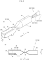
- Fig. 1(a) is an external view of a crimp terminal 10, and a wire tip 500T
- Fig. 1(b) is a vertical sectional view of an intermediate portion of the crimp terminal 10 in a width direction.
- a longitudinal direction of the crimp terminal 10 (the terminal metal fitting 10A) is set as a terminal axis direction Lt, and a width direction of the crimp terminal 10 is set as a terminal width direction Wt.
- the terminal width direction Wt is a direction that matches the carrier longitudinal direction Lc.
- a box portion 20 side of a crimping section 60 in the terminal axis direction Lt is set as a front Ltf (a tip side), and oppositely, a crimping section 60 side of the box portion 20 is set as a back Ltb (a base end side).
- a thickness direction D of the crimp terminal 10 (the terminal metal fitting 10A)
- one side in a thickness direction of bend processing around the terminal axis is set as an upper direction (Du).
- the crimp terminal 10 is in a closed barrel type, and is formed in a female crimp terminal shape.
- the crimp terminal 10 is integrally configured by the box portion 20 that permits the insertion of an insertion tab of the female crimp terminal 10 not shown, a sealing portion 50 which is formed in a transition section 40 of a predetermined length at the back of the box portion 20, and a crimping section 60 which is arranged continuously with the sealing portion 50 in the terminal axis direction via the transition section 40, from the front Ltf as the tip side of the terminal axis direction Lt toward the back Ltb.
- the box portion 20 is configured by an inverse hollow square pole, and includes in the inside an elastic contact piece 21 which is in contact with an insertion tab (not shown) of a male connector which is to be inserted by being returned backward in the terminal axis direction Lt.
- the box portion 20 as the hollow square pole is configured in a cuboid shape which is slender in the terminal axis direction Lt, by having a right side surface part 22, a left side surface part 23, an upper surface part 24, and a bottom surface part 25 confronted to each other.
- the box portion 20 has the right side surface part 22 and a one side upper surface part 240 continuously provided to the bottom surface part 25 toward the outside at one side of the terminal width direction Wt, and has the left side surface part 23 and the other side upper surface part 241 continuously provided toward the outside at the side of the terminal width direction Wt, in a developed shape, as shown in Fig. 1(a) .
- the one side upper surface part 240 and the other side upper surface part 241 are overlapped with each other, and configure the upper surface part 24, when the surface parts that configure the box portion 20 are folded in a peripheral direction to be configured in the cuboid shape.
- the sealing portion 50 is configured in a flat shape, by deforming the portions of the transition section 40 at the crimping section 60 to be crushed in approximately a flat-sheet shape mutually overlapping predetermined portions that are opposite in a vertical direction.
- the crimping section 60 is formed in a cylindrical shape capable of inserting the wire tip 500T at least at a tip side of an insulated wire 500, and is also integrally formed in a continuous shape continuous in a whole peripheral direction.
- a length of the crimping section 60 is not particularly limited so far as the crimping section 60 includes a length in which a conductor tip 510T described later of the insulated wire 500 is inserted.
- the insulated wire 500 is configured by covering a conductor 510 with an insulating cover 520 configured by an insulating resin.
- the conductor 510 is formed by superposing a plurality of aluminum raw wires 221 formed by aluminum or an aluminum alloy, as shown in Fig. 1(a) .
- the wire tip 500T is configured by the conductor tip 510T obtained by exposing the conductor 510 by peeling off the tip-side insulating cover 520, at the tip side of the insulated wire 500, and a cover tip 520T at the tip side of the insulating cover portion at the back of the conductor tip 510T at the tip side of the insulated wire 500, as shown in Fig. 1(a) .
- a welding part 61 where opposed end parts 60t are welded together is formed along the terminal axis direction Lt, at opposed portions where the opposed end parts 60t are opposed to each other in the peripheral direction.
- the crimping section 60 is electrically connected to the wire tip 500T, by crimping by swaging in the state that the wire tip 500T is inserted.
- a portion corresponding to the sealing portion 50 of the transition corresponding part 40A is set to a sealing portion corresponding part 50.
- a portion corresponding to the box portion 20 is set to a box-portion corresponding part 20A
- a portion corresponding to the transition section 40 is set to the transition corresponding part 40A
- a portion corresponding to the crimping section 60 is set to the crimping portion corresponding part 60A.
- each of the bottom surface part 25, the right side surface part 22, the left side surface part 23, and the upper surface part 24 (the one side upper surface part 240, and the other side upper surface part 241) is set to a bottom-surface corresponding part 25A, a right-side surface corresponding part 22A, a left-side surface corresponding part 23A, and an upper-surface corresponding part 24A (a one-side upper surface corresponding part 240A, and the other-side upper surface corresponding part 241A), respectively.
- a portion corresponding to the sealing portion 50 of the transition corresponding part 40A is set to a sealing portion corresponding part 50.
- a crimp terminal 10P has a notched part 70 that is notched from a base end side, on sidewalls at both sides of the terminal width direction Wt in a continuously-provided portion between the transition section 40 (the sealing portion 50) and the box portion 20, as shown in Figs. 2(a) and 2(b) .
- the notched part 70 will be described based on the crimp terminal in a developed shape described later. As shown in Fig. 3 , an external end part in the terminal width direction Wt is formed by notching, at a continuously-provided portion between the right side surface part 22A of the box-portion corresponding part 20A and the transition corresponding part 40A of the left-side surface corresponding part 23A.
- the bend processing of the box-portion corresponding part 20A is performed in advance .
- the bend processing of the crimping portion corresponding part 60A is performed.
- the transition corresponding part 40A when the transition corresponding part 40A is formed long, a total length of the crimp terminal 10P also becomes long accordingly.
- the crimp terminal 10P becomes of a terminal length that does not satisfy the predetermined standard, and there arises a separate problem that the crimp terminal 10P cannot be properly inserted into a terminal insertion hole of the connector not shown.
- the crimp terminal 10P of the present embodiment by forming the notched part 70 in the continuously-provided portion between the box-portion corresponding part 20A and the transition corresponding part 40A, the excessive stress that works due to the difference in the deformation amount in the boundary portion in the process of bend processing the box-portion corresponding part 20A can be also dispersed to the continuously-provided portion having the notched part 70.
- the notched part 70 is formed in the continuously-provided portion between the box-portion corresponding part 20A and the transition corresponding part 40A, stress concentration applied to the transition corresponding part 40A can be mitigated at the time of bend processing the box-portion corresponding part 20A, without forming the transition corresponding part 40A itself long.
- a whole length of the crimp terminal 10P is maintained in the terminal length that satisfies the predetermined standard, a whole length of the crimp terminal 10P can be maintained in the terminal length that satisfies the predetermined standard such as a length in which the crimp terminal 10P can be properly inserted into the terminal insertion hole of the connector.
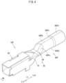
- the crimp terminal 10P is formed such that a crimping section 60P is in a staged shape having different diameters in the terminal axis direction Lt, as shown in Fig. 4 , without being formed in the same diameter along the terminal axis direction Lt.
- Fig. 4 shows a perspective view of the crimp terminal 10P in the other embodiment.
- the crimping section 60P is integrally configured by a tip-side open block part 60Pa, a conductor crimping section 60Pb, a step 60Pc, and a cover crimping section 60Pd.
- the conductor crimping section 60Pb is a portion corresponding to the conductor tip 510T that is inserted in the terminal axis direction Lt in the state that the wire tip 500T is inserted.
- the conductor crimping section 60Pb is formed to have an internal diameter approximately equal to or slightly larger than the external diameter of the conductor tip 510T, and in a diameter smaller than the external diameter of the cover crimping section 60Pd.
- the cover crimping section 60Pd is a portion corresponding to the cover tip 520T that is inserted in the terminal axis direction Lt in the state that the wire tip 500T is inserted.
- the cover crimping section 60Pd is formed to have an internal diameter approximately equal to or slightly larger than the external diameter of the cover tip 520T.
- the step 60Pc between the conductor crimping section 60Pb and the cover crimping section 60Pd of the crimping section 60P is not in a step shape that is orthogonal with the terminal axis direction Lt, and is formed in a step shape in which a diameter smoothly reduces from the cover crimping section 60Pd toward the conductor crimping section 60Pb.
- the tip-side open block part 60Pa is a portion where the tip side of the cylindrical crimping section 60P in the terminal axis direction Lt is blocked not be opened.
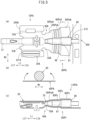
- the above crimp terminal 10P is manufactured as shown in Figs. 5(a), 5(b) , and 5(c) by using a stepped core bar 80 to a terminal metal member 10PA as shown in Fig. 3 .
- Fig. 5(a) is a plan view of the terminal metal member 10PA, and shows a plan view of a state that a core bar 600 is arranged in the crimping portion corresponding part 60PA of the terminal metal member 10PA.
- Fig. 5(b) shows a sectional view of an arrow I-I in Fig. 5(a).
- Fig. 5(c) shows a vertical sectional view of a state that the crimping portion corresponding part 60PA is cylindrically formed.
- the terminal metal member 10PA has the box-portion corresponding part 20A, the transition corresponding part 40A, and the crimping portion corresponding part 60PA arranged in this order along the tip side Ltf to the base end side Ltb in the terminal axis direction Lt, as shown in Figs. 3 and 5(a) .
- the sealing portion corresponding part 50A is arranged in the back side portion of the transition corresponding part 40A in the terminal axis direction Lt.
- the tip-side opening block corresponding part 60PaA is formed to become gradually small along the base end side Ltb to the tip side Ltf in the terminal axis direction Lt to make it possible to continuously provide the crimping portion corresponding part 60PA and the sealing portion corresponding part 50A.
- the step-portion corresponding part 60PcA corresponds to the step 60Pc, and is formed by inclining the external edge part in the width direction to the terminal axis direction Lt to become gradually in a small width along the base end side Ltb to the tip side Ltf in the terminal axis direction Lt according to respective sizes of the conductor crimping portion corresponding part 60PbA and the cover crimping portion corresponding part 60PdA.
- cover crimping portion corresponding part 60PdA and the conductor crimping portion corresponding part 60PbA are also formed by inclining the external edge parts in the respective width directions to the terminal axis direction Lt to become gradually in small widths along the base end side Ltb to the tip side Ltf in the terminal axis direction Lt.
- the base end side end part of the crimping portion corresponding part 60PA is formed by inclining the external portion in the terminal width direction Wt to the terminal width direction Wt with respect to the connection part 310 provided in the intermediate portion in the terminal width direction Wt, so that an interval from the carrier 320 in the terminal axis direction Lt gradually spreads.
- the external end parts at both sides of the sealing portion corresponding part 50A in the terminal width direction Wt are formed in parallel without inclination to the terminal axis direction Lt.
- Serrations 68 (engagement grooves) are formed in the conductor crimping portion corresponding part 60PbA.
- the serrations 68 are formed over a whole length of the terminal width direction Wt of the conductor crimping portion corresponding part 60PbA, and are also formed in bow shapes in a plan-view such that a center portion relative to outside in the terminal width direction Wt is gradually curved to the base end side in the terminal width direction Wt.
- the above crimp terminal 10P can be manufactured by bend processing by using the stepped core bar 80 to the terminal metal member 10PA in the fifth terminal processing process to the sixth terminal processing process.
- the stepped core bar 80 is arranged from the sealing portion corresponding part 50A to the crimping portion corresponding part 60PA along the axis terminal direction Lt of the intermediate portion in the terminal width direction Wt of the sealing portion corresponding part 50A of the terminal metal member 10PA and the crimping portion corresponding part 60PA.
- a step portion 81 of the stepped core bar 80 and the step-portion corresponding part 60PcA of the crimping portion corresponding part 60PA are arranged in a positioned state in the terminal axis direction Lt.
- portions of the sealing portion corresponding part 50A and the crimping portion corresponding part 60PA are cylindrically bend processed along the external peripheral surface of the stepped core bar 80 so that the stepped core bar 80 is surrounded by the sealing portion corresponding part 50A and the crimping portion corresponding part 60PA by suitably pressurizing from the outside by a pressuring mold not shown.
- the sealing portion corresponding part 50A and the crimping portion corresponding part 60PA surround the stepped core bar 80 by bringing the bow-shaped step-portion corresponding part 60PcA into contact with the external peripheral surface of the step portion 81 of the stepped core bar 80.
- the step 60Pc of the crimping section 60P is formed in a step shape by smoothly reducing the diameter from the cover crimping section 60Pd to the conductor crimping section 60Pb. Therefore, at the time of inserting the wire tip 500T into the crimping section 60P, the raw wires that configure the conductor tip 510T are not scattered due to the conductor tip 510T being caught by the step part 60Pc. The wire tip 500T can be smoothly inserted deep into the crimping section 60P.
- the sealing portion corresponding part 50A and the crimping portion corresponding part 60PA are bend processed to surround the core bar 80 in the state of being positioned in the terminal axis direction Lt in such a manner that the step-portion corresponding part 60PcA formed in a bow shape in the plan view is pressed against the external surface of the step portion 81 of the stepped core bar 80.
- the step part 60Pc is securely formed in the step-portion corresponding part 60PcA without causing the step part 60Pc to be positionally deviated in the terminal axis direction Lt.
- the step part 60Pc is formed at a predetermined position without a variation of the step part 60Pc in the terminal axis direction Lt of the crimping section in each crimp terminal 10P.
- the cover crimping section 60Pd When the cover crimping section 60Pd is formed longer than a desired length in the terminal axis direction Lt, the cover crimping section 60Pd is positioned around a base end side Xb of the conductor tip 510T, even when the wire tip 500T is inserted by a proper insertion amount inside the crimping section.
- the gap between the conductor tip 510T and the cover crimping section 60Pd is larger than the gap between the conductor tip 510T and the conductor crimping section 60Pb, when the wire tip 500T and the crimping section 60P are crimp connected to each other, there has been a risk that what is called the inside-fall portion 600z is formed in the crimping section 60P at the base end side Xb of the conductor tip 510T.
- the step part 60Pc is formed at a desired position in the terminal axis direction Lt of the crimping section 60P by using the stepped core bar 80. Therefore, the wire tip 500T can be smoothly inserted into the crimping section 60P by a proper insertion amount.
- wires with a terminal having a satisfactory electric connection characteristic can be efficiently manufactured, by crimp connecting the crimping section 60P to the wire tip 500T in a close contact state.
- the crimp terminal 10P of the present embodiment is formed by inclining the external end parts at both sides in the terminal width direction Lw of the crimping portion corresponding part 60PA, more specifically, the tip-side opening block corresponding part 60PaA, the conductor crimping portion corresponding part 60PbA, the step-portion corresponding part 60PcA, and the cover crimping portion corresponding part 60PdA, to the terminal axis direction Lt so that the external end parts become gradually smaller along the base end side Ltb to the tip side Ltf in the terminal axis direction Lt, as described above.
- the base end side end part of the crimping portion corresponding part 60PA is also formed by inclining the external portion in the terminal width direction Wt to the connection part 310 having the intermediate portion in the terminal width direction Wt, to the terminal width direction Wt so that an interval from the carrier 320 gradually spreads along the outside in the in the terminal width direction Wt.
- the crimping portion corresponding part 60PA can be formed, by forming the external peripheral edge in the above shape, by compression based on pressurizing of the pressurizing mold, not shown, used at the time of cylindrical bend processing, considering extension of the material generated in the crimping portion corresponding part 60PA.
- the end parts 6ot that are opposed in the peripheral direction can be butted against each other without a gap along the terminal axis direction Lt.
- the stepped crimping section 60P including the conductor crimping section 60Pb and the cover crimping section 60Pd can be securely formed.
- the shaping process is performed to perform a cylindrical bend processing.
- the insulated wire 500 that is connected to the crimp terminals 10 and 10P is not limited to only covering the conductor 510 of a copper system made of aluminum or an aluminum alloy with the insulating cover 520.
- the insulated wire 500 may be provided by covering the conductor 510 of a copper system made of copper or a copper alloy with the insulating cover 520, for example.
- the conductor 510 may be a dissimilar mixed conductor obtained by bundling by arranging aluminum raw wires around copper system raw wires, or may be a dissimilar mixed conductor obtained by bundling by arranging copper system raw wires around aluminum raw wire.
Landscapes
- Engineering & Computer Science (AREA)
- Manufacturing & Machinery (AREA)
- Connections Effected By Soldering, Adhesion, Or Permanent Deformation (AREA)
- Manufacturing Of Electrical Connectors (AREA)
Claims (1)
- Une borne de sertissage (10) et un fil isolé (500) comprenant un conducteur (510) avec une couverture isolante (520), la borne de sertissage (10) comprenant :une partie de connexion à connecter à un élément de connexion de l'autre côté, une section de transition et une section de sertissage cylindrique (60P), disposées dans cet ordre, d'un côté de la pointe à un côté de la base dans une direction d'axe terminal (Lt), la section de transition joignant la partie de connexion et la section de sertissage (60P),
la section de transition est formée par le relèvement d'un fond de la partie de connexion et d'une section de sertissage du conducteur (60Pb),la section de sertissage cylindrique (60P) qui sertit une pointe de fil (500T) dont la couverture isolante (520) a été décollée au moins au niveau d'un côté de la pointe du fil isolé (500), et une portion de scellement (50) pour sceller une partie d'ouverture de la section de sertissage (60P) au niveau d'un côté de la pointe dans une direction de l'axe terminal (Lt), une direction longitudinale de la borne de sertissage (10) étant définie comme la direction de l'axe terminal (Lt), dans laquellela section de sertissage (60P) comprendla section de sertissage du conducteur (60Pb) qui sertit une pointe de conducteur (510T), une section de sertissage du couvercle (60Pd) qui sertit une pointe de couvercle (520T), et une marche (60Pc) qui est positionnée entre la section de sertissage du conducteur (60Pb) et la section de sertissage du couvercle (60Pd),la section de sertissage (60P) est fabriquée à partir d'une partie correspondante à la section de sertissage (60PA) qui correspond à la section de sertissage (60P) avant un traitement de pliage,la partie correspondant à la portion de sertissage (60PA) a une largeur correspondant à une circonférence externe de la section de sertissage du conducteur (60Pb), de la marche (60Pc) et de la section de sertissage du couvercle (60Pd), le long d'un côté d'extrémité de base (Ltb) à un côté de pointe (Ltf) dans la direction de l'axe terminal (Lt), respectivement, et a une partie d'extrémité (60t) externe inclinée séparément par rapport à la direction de l'axe terminal (Lt) de manière à devenir graduellement plus petite en largeur, etla portion de scellement (50) est fabriquée à partir d'une partie correspondante à la portion de scellement (50A) qui correspond à la portion de scellement (50) avant le traitement de pliage,la partie correspondante de la portion de scellement (50A) a une largeur correspondant à une circonférence externe de la portion de scellement (50), et est également formée de telle sorte qu'une partie d'extrémité de la partie correspondante de la portion de scellement (50A) a des bords qui sont approximativement parallèles à la direction de l'axe terminal (Lt), de telle sorte qu'après le traitement de pliage de la partie correspondante de la portion de sertissage (60PA), les parties opposées où les parties d'extrémité (60t) opposées sont aboutées dans la direction périphérique peuvent être pliées cylindriquement sans générer d'espace.
Applications Claiming Priority (3)
| Application Number | Priority Date | Filing Date | Title |
|---|---|---|---|
| JP2013034026 | 2013-02-23 | ||
| JP2013124354 | 2013-06-13 | ||
| PCT/JP2014/050324 WO2014129229A1 (fr) | 2013-02-23 | 2014-01-10 | Corps cylindrique, borne de sertissage, procédé pour fabriquer ledit corps et ladite borne, et dispositif pour fabriquer ladite borne de sertissage |
Publications (3)
| Publication Number | Publication Date |
|---|---|
| EP2960992A1 EP2960992A1 (fr) | 2015-12-30 |
| EP2960992A4 EP2960992A4 (fr) | 2017-03-08 |
| EP2960992B1 true EP2960992B1 (fr) | 2024-11-20 |
Family
ID=51391025
Family Applications (1)
| Application Number | Title | Priority Date | Filing Date |
|---|---|---|---|
| EP14753750.0A Active EP2960992B1 (fr) | 2013-02-23 | 2014-01-10 | Borne a sertir |
Country Status (6)
| Country | Link |
|---|---|
| US (2) | US9608338B2 (fr) |
| EP (1) | EP2960992B1 (fr) |
| JP (3) | JP5579342B1 (fr) |
| KR (1) | KR101817614B1 (fr) |
| CN (2) | CN108258442B (fr) |
| WO (1) | WO2014129229A1 (fr) |
Families Citing this family (12)
| Publication number | Priority date | Publication date | Assignee | Title |
|---|---|---|---|---|
| CN104350644B (zh) * | 2013-02-20 | 2016-04-20 | 古河电气工业株式会社 | 压接端子、连接构造体以及连接构造体的制造方法 |
| CN104272535B (zh) * | 2013-02-22 | 2019-03-19 | 古河电气工业株式会社 | 压接端子的制造方法、压接端子及线束 |
| JP5603524B1 (ja) * | 2013-02-23 | 2014-10-08 | 古河電気工業株式会社 | 圧着端子、圧着端子の製造方法、電線接続構造体、及び電線接続構造体の製造方法 |
| CN105637707B (zh) | 2013-10-15 | 2019-05-21 | 古河As株式会社 | 端子、线束和线束结构体 |
| CN108213870B (zh) * | 2017-12-30 | 2023-10-17 | 温州益能电器有限公司 | 一种插簧端子的专用模具及其加工方法 |
| DE102018111628A1 (de) * | 2018-05-15 | 2019-11-21 | Würth Elektronik Ics Gmbh & Co. Kg | Steckervorrichtung mit Lamellen und Verriegelungselement |
| JP6734952B1 (ja) * | 2019-02-05 | 2020-08-05 | 株式会社エフテック | 筒状部材及び筒状部材の製造方法 |
| CN110797820B (zh) * | 2019-10-23 | 2021-06-11 | 山东达驰阿尔发电气有限公司 | 一种离相封闭母线导体抱瓦的制作方法 |
| CN110783793B (zh) * | 2019-11-08 | 2021-04-20 | 深圳市虹宇电子有限公司 | 一种电子线束接线端子整形机械及其方法 |
| JP7560966B2 (ja) * | 2020-06-08 | 2024-10-03 | モレックス エルエルシー | ケーブル端子及びコネクタ |
| JP7234188B2 (ja) * | 2020-07-22 | 2023-03-07 | 矢崎総業株式会社 | 電線の製造方法および電線製造装置 |
| US12244114B2 (en) * | 2021-11-16 | 2025-03-04 | Te Connectivity Solutions Gmbh | High deformation and retention ferrule |
Citations (2)
| Publication number | Priority date | Publication date | Assignee | Title |
|---|---|---|---|---|
| JP2004071437A (ja) * | 2002-08-08 | 2004-03-04 | Sumitomo Wiring Syst Ltd | 自動車用アース端子と電線の防水接続構造 |
| DE10360614A1 (de) * | 2002-12-20 | 2004-07-22 | Yazaki Corp. | Verfahren zum Verbinden eines Verbindungselements mit einem elektrischen Kabel |
Family Cites Families (37)
| Publication number | Priority date | Publication date | Assignee | Title |
|---|---|---|---|---|
| US2012796A (en) * | 1931-09-01 | 1935-08-27 | Republie Steel Corp | Method and apparatus for forming tubes |
| US3955044A (en) * | 1970-12-03 | 1976-05-04 | Amp Incorporated | Corrosion proof terminal for aluminum wire |
| US3828706A (en) * | 1973-01-02 | 1974-08-13 | Ideal Ind | Method of making a terminal |
| US4076988A (en) * | 1976-08-17 | 1978-02-28 | Westinghouse Electric Corporation | Superconducting dynamoelectric machine having a liquid metal shield |
| CN1003704B (zh) * | 1986-04-06 | 1989-03-29 | 蓬莱县南王乡团结农机修造厂 | 冷冲压双金属卷筒轴套翻边工艺 |
| US5254022A (en) * | 1989-07-28 | 1993-10-19 | Edward W. Burger | Electrical connector device and method of manufacturer thereof |
| JPH06302341A (ja) * | 1993-04-16 | 1994-10-28 | Yazaki Corp | レーザ溶接構造及びレーザ溶接端子 |
| JP3007781B2 (ja) * | 1993-11-30 | 2000-02-07 | 矢崎総業株式会社 | 防水ゴム栓挿入用端子 |
| JP3094138B2 (ja) * | 1994-06-30 | 2000-10-03 | 矢崎総業株式会社 | バレル端子及び電線接続装置 |
| EP1191632B1 (fr) * | 2000-09-21 | 2005-12-21 | Yazaki Corporation | Dispositif et procédé pour connecter une borne avec un fil électrique |
| JP2003025026A (ja) | 2001-07-13 | 2003-01-28 | Sumitomo Wiring Syst Ltd | 金型装置及び金型装置を用いた加工方法 |
| FR2840736B1 (fr) * | 2002-06-11 | 2004-08-27 | Framatome Connectors Int | Borne de contact electrique femelle d'une seule piece ayant une partie de transition renforcee |
| JP3866631B2 (ja) * | 2002-07-30 | 2007-01-10 | 三菱電線工業株式会社 | 雄型棒状接続端子及びその製造方法 |
| JP2004071439A (ja) | 2002-08-08 | 2004-03-04 | Sumitomo Wiring Syst Ltd | コネクタ |
| EP1503454B1 (fr) * | 2003-07-30 | 2015-08-05 | Furukawa Electric Co. Ltd. | Assemblage de cosse sertie sur cable d'aluminium et méthode de fabrication |
| JP4066978B2 (ja) * | 2004-05-24 | 2008-03-26 | 住友電装株式会社 | ファストン端子 |
| JP2006293693A (ja) | 2005-04-11 | 2006-10-26 | Matsushita Electric Ind Co Ltd | 2次元逆変換装置 |
| JP4941067B2 (ja) * | 2007-04-13 | 2012-05-30 | 住友電装株式会社 | 端子金具 |
| US7402089B1 (en) * | 2007-05-04 | 2008-07-22 | Tyco Electronics Corporation | Contact with enhanced transition region |
| JP4941095B2 (ja) * | 2007-05-22 | 2012-05-30 | 住友電装株式会社 | 端子金具 |
| JP5329100B2 (ja) * | 2008-01-23 | 2013-10-30 | 矢崎総業株式会社 | 電線付きコネクタ端子が挿入されたコネクタ |
| JP5065125B2 (ja) * | 2008-03-31 | 2012-10-31 | 古河電気工業株式会社 | 圧着端子 |
| JP5184222B2 (ja) * | 2008-06-12 | 2013-04-17 | 株式会社オートネットワーク技術研究所 | 端子圧着用金型及び端子金具付き電線の製造方法 |
| JP2010055874A (ja) * | 2008-08-27 | 2010-03-11 | Sumitomo Wiring Syst Ltd | 端子金具と電線の接続構造 |
| JP5219877B2 (ja) * | 2009-02-16 | 2013-06-26 | 矢崎総業株式会社 | 同軸ケーブル用コネクタ |
| JP2010198789A (ja) * | 2009-02-23 | 2010-09-09 | Fujikura Ltd | 圧着端子の端子構造 |
| JP5237154B2 (ja) * | 2009-03-04 | 2013-07-17 | 株式会社オートネットワーク技術研究所 | 圧着端子および端子付き電線 |
| JP5399800B2 (ja) * | 2009-07-17 | 2014-01-29 | 矢崎総業株式会社 | 防水構造 |
| JP2011103262A (ja) * | 2009-11-12 | 2011-05-26 | Yazaki Corp | 圧着端子および端子の圧着方法 |
| CN102742083B (zh) * | 2010-02-05 | 2015-05-20 | 古河电气工业株式会社 | 压接端子、连接构造体以及压接端子的制作方法 |
| EP2555328A4 (fr) * | 2010-03-30 | 2014-05-21 | Furukawa Electric Co Ltd | Borne de sertissage, corps de structure de connexion et connecteur |
| JP5539009B2 (ja) * | 2010-05-14 | 2014-07-02 | 矢崎総業株式会社 | 圧着端子の電線に対する接続構造 |
| JP5777861B2 (ja) * | 2010-06-14 | 2015-09-09 | 古河電気工業株式会社 | ワイヤハーネス、及び電線端子防食構造の生産方法 |
| JP5947576B2 (ja) * | 2012-03-16 | 2016-07-06 | 矢崎総業株式会社 | 圧着端子付き電線 |
| ES2566360T3 (es) * | 2012-04-12 | 2016-04-12 | Yazaki Europe Ltd | Terminal eléctrico |
| JP2014103445A (ja) * | 2012-11-16 | 2014-06-05 | Ricoh Co Ltd | 自動原稿搬送装置、画像読取装置および画像形成装置 |
| JP5889228B2 (ja) * | 2013-02-22 | 2016-03-22 | 古河電気工業株式会社 | 端子付電線製造方法、及び芯線露出装置 |
-
2014
- 2014-01-10 JP JP2014508202A patent/JP5579342B1/ja active Active
- 2014-01-10 KR KR1020157023622A patent/KR101817614B1/ko active Active
- 2014-01-10 CN CN201810163723.1A patent/CN108258442B/zh active Active
- 2014-01-10 CN CN201480010054.4A patent/CN105075020B/zh active Active
- 2014-01-10 WO PCT/JP2014/050324 patent/WO2014129229A1/fr not_active Ceased
- 2014-01-10 EP EP14753750.0A patent/EP2960992B1/fr active Active
- 2014-05-19 JP JP2014103445A patent/JP5639299B1/ja active Active
- 2014-08-29 JP JP2014175559A patent/JP5697062B2/ja active Active
-
2015
- 2015-08-21 US US14/832,682 patent/US9608338B2/en active Active
-
2017
- 2017-01-30 US US15/419,608 patent/US10763596B2/en active Active
Patent Citations (2)
| Publication number | Priority date | Publication date | Assignee | Title |
|---|---|---|---|---|
| JP2004071437A (ja) * | 2002-08-08 | 2004-03-04 | Sumitomo Wiring Syst Ltd | 自動車用アース端子と電線の防水接続構造 |
| DE10360614A1 (de) * | 2002-12-20 | 2004-07-22 | Yazaki Corp. | Verfahren zum Verbinden eines Verbindungselements mit einem elektrischen Kabel |
Also Published As
| Publication number | Publication date |
|---|---|
| WO2014129229A1 (fr) | 2014-08-28 |
| JP5639299B1 (ja) | 2014-12-10 |
| EP2960992A1 (fr) | 2015-12-30 |
| JP5697062B2 (ja) | 2015-04-08 |
| CN105075020B (zh) | 2018-04-06 |
| JP2015018794A (ja) | 2015-01-29 |
| US10763596B2 (en) | 2020-09-01 |
| KR20150121013A (ko) | 2015-10-28 |
| CN105075020A (zh) | 2015-11-18 |
| US9608338B2 (en) | 2017-03-28 |
| KR101817614B1 (ko) | 2018-01-11 |
| US20160006135A1 (en) | 2016-01-07 |
| CN108258442B (zh) | 2020-09-18 |
| EP2960992A4 (fr) | 2017-03-08 |
| CN108258442A (zh) | 2018-07-06 |
| JPWO2014129229A1 (ja) | 2017-02-02 |
| JP2015018816A (ja) | 2015-01-29 |
| JP5579342B1 (ja) | 2014-08-27 |
| US20170141485A1 (en) | 2017-05-18 |
Similar Documents
| Publication | Publication Date | Title |
|---|---|---|
| US10763596B2 (en) | Manufacturing method of cylindrical body crimp terminal | |
| JP5107693B2 (ja) | 圧着構造及び圧着方法 | |
| JP6543304B2 (ja) | 端子付き電線、端子圧着装置及び端子付き電線の製造方法 | |
| CN107453182B (zh) | 具有端子的电线的制造方法 | |
| JP6546626B2 (ja) | 端子付き電線、端子圧着装置及び端子付き電線の製造方法 | |
| JP2010040404A (ja) | 端子金具及びワイヤーハーネス | |
| CN105580202A (zh) | 用于在电线路与导电构件之间建立导电连接的方法 | |
| JP2011044423A (ja) | 圧着端子金具及び端子金具付き電線 | |
| CN104247154A (zh) | 将端子压接到电线的方法与压接端子 | |
| KR102513547B1 (ko) | 코일단말의 접속구조 | |
| JP2009245700A (ja) | 圧着端子 | |
| JP2021034307A (ja) | 端子、および端子付き電線 | |
| JP6519440B2 (ja) | 端子付き電線の製造方法、および圧着治具 | |
| JP6093668B2 (ja) | 圧着端子 | |
| JP2009224079A (ja) | 内導体端子、連鎖端子、及び、同軸ケーブルと内導体端子との圧着接続方法 | |
| JP3063881U (ja) | 接触部材 | |
| JP6560695B2 (ja) | 接続方法 | |
| JP2010118238A (ja) | 端子金具と電線の接続構造 | |
| JP2019046655A (ja) | 端子付き電線の製造方法、端子付き電線および端子圧着装置 | |
| JP2025186769A (ja) | 圧着接続端子の導体圧着方法 | |
| JP2017098109A (ja) | 端子付き電線及びその製造方法 | |
| JP2017117724A (ja) | 端子付き電線の製造方法、圧着治具、および端子付き電線 | |
| JP2010080333A (ja) | 端子金具付き電線及び端子金具 |
Legal Events
| Date | Code | Title | Description |
|---|---|---|---|
| PUAI | Public reference made under article 153(3) epc to a published international application that has entered the european phase |
Free format text: ORIGINAL CODE: 0009012 |
|
| 17P | Request for examination filed |
Effective date: 20150907 |
|
| AK | Designated contracting states |
Kind code of ref document: A1 Designated state(s): AL AT BE BG CH CY CZ DE DK EE ES FI FR GB GR HR HU IE IS IT LI LT LU LV MC MK MT NL NO PL PT RO RS SE SI SK SM TR |
|
| AX | Request for extension of the european patent |
Extension state: BA ME |
|
| DAX | Request for extension of the european patent (deleted) | ||
| A4 | Supplementary search report drawn up and despatched |
Effective date: 20170202 |
|
| RIC1 | Information provided on ipc code assigned before grant |
Ipc: H01R 43/16 20060101AFI20170127BHEP Ipc: H01R 43/048 20060101ALN20170127BHEP Ipc: H01R 4/62 20060101ALN20170127BHEP |
|
| STAA | Information on the status of an ep patent application or granted ep patent |
Free format text: STATUS: EXAMINATION IS IN PROGRESS |
|
| 17Q | First examination report despatched |
Effective date: 20171120 |
|
| REG | Reference to a national code |
Ref country code: DE Ref legal event code: R079 Free format text: PREVIOUS MAIN CLASS: H01R0004180000 Ref country code: DE Ref legal event code: R079 Ref document number: 602014091204 Country of ref document: DE Free format text: PREVIOUS MAIN CLASS: H01R0004180000 Ipc: H01R0043160000 |
|
| GRAP | Despatch of communication of intention to grant a patent |
Free format text: ORIGINAL CODE: EPIDOSNIGR1 |
|
| STAA | Information on the status of an ep patent application or granted ep patent |
Free format text: STATUS: GRANT OF PATENT IS INTENDED |
|
| RIC1 | Information provided on ipc code assigned before grant |
Ipc: H01R 43/048 20060101ALN20240613BHEP Ipc: H01R 4/62 20060101ALN20240613BHEP Ipc: H01R 4/20 20060101ALI20240613BHEP Ipc: H01R 43/16 20060101AFI20240613BHEP |
|
| INTG | Intention to grant announced |
Effective date: 20240626 |
|
| GRAS | Grant fee paid |
Free format text: ORIGINAL CODE: EPIDOSNIGR3 |
|
| GRAA | (expected) grant |
Free format text: ORIGINAL CODE: 0009210 |
|
| STAA | Information on the status of an ep patent application or granted ep patent |
Free format text: STATUS: THE PATENT HAS BEEN GRANTED |
|
| AK | Designated contracting states |
Kind code of ref document: B1 Designated state(s): AL AT BE BG CH CY CZ DE DK EE ES FI FR GB GR HR HU IE IS IT LI LT LU LV MC MK MT NL NO PL PT RO RS SE SI SK SM TR |
|
| P01 | Opt-out of the competence of the unified patent court (upc) registered |
Free format text: CASE NUMBER: APP_55639/2024 Effective date: 20241010 |
|
| REG | Reference to a national code |
Ref country code: GB Ref legal event code: FG4D |
|
| REG | Reference to a national code |
Ref country code: CH Ref legal event code: EP |
|
| REG | Reference to a national code |
Ref country code: DE Ref legal event code: R096 Ref document number: 602014091204 Country of ref document: DE |
|
| REG | Reference to a national code |
Ref country code: IE Ref legal event code: FG4D |
|
| REG | Reference to a national code |
Ref country code: LT Ref legal event code: MG9D |
|
| REG | Reference to a national code |
Ref country code: NL Ref legal event code: MP Effective date: 20241120 |
|
| PG25 | Lapsed in a contracting state [announced via postgrant information from national office to epo] |
Ref country code: PT Free format text: LAPSE BECAUSE OF FAILURE TO SUBMIT A TRANSLATION OF THE DESCRIPTION OR TO PAY THE FEE WITHIN THE PRESCRIBED TIME-LIMIT Effective date: 20250320 Ref country code: HR Free format text: LAPSE BECAUSE OF FAILURE TO SUBMIT A TRANSLATION OF THE DESCRIPTION OR TO PAY THE FEE WITHIN THE PRESCRIBED TIME-LIMIT Effective date: 20241120 Ref country code: IS Free format text: LAPSE BECAUSE OF FAILURE TO SUBMIT A TRANSLATION OF THE DESCRIPTION OR TO PAY THE FEE WITHIN THE PRESCRIBED TIME-LIMIT Effective date: 20250320 |
|
| PG25 | Lapsed in a contracting state [announced via postgrant information from national office to epo] |
Ref country code: FI Free format text: LAPSE BECAUSE OF FAILURE TO SUBMIT A TRANSLATION OF THE DESCRIPTION OR TO PAY THE FEE WITHIN THE PRESCRIBED TIME-LIMIT Effective date: 20241120 Ref country code: NL Free format text: LAPSE BECAUSE OF FAILURE TO SUBMIT A TRANSLATION OF THE DESCRIPTION OR TO PAY THE FEE WITHIN THE PRESCRIBED TIME-LIMIT Effective date: 20241120 |
|
| REG | Reference to a national code |
Ref country code: AT Ref legal event code: MK05 Ref document number: 1744455 Country of ref document: AT Kind code of ref document: T Effective date: 20241120 |
|
| PG25 | Lapsed in a contracting state [announced via postgrant information from national office to epo] |
Ref country code: BG Free format text: LAPSE BECAUSE OF FAILURE TO SUBMIT A TRANSLATION OF THE DESCRIPTION OR TO PAY THE FEE WITHIN THE PRESCRIBED TIME-LIMIT Effective date: 20241120 |
|
| PG25 | Lapsed in a contracting state [announced via postgrant information from national office to epo] |
Ref country code: ES Free format text: LAPSE BECAUSE OF FAILURE TO SUBMIT A TRANSLATION OF THE DESCRIPTION OR TO PAY THE FEE WITHIN THE PRESCRIBED TIME-LIMIT Effective date: 20241120 |
|
| PG25 | Lapsed in a contracting state [announced via postgrant information from national office to epo] |
Ref country code: NO Free format text: LAPSE BECAUSE OF FAILURE TO SUBMIT A TRANSLATION OF THE DESCRIPTION OR TO PAY THE FEE WITHIN THE PRESCRIBED TIME-LIMIT Effective date: 20250220 |
|
| PG25 | Lapsed in a contracting state [announced via postgrant information from national office to epo] |
Ref country code: LV Free format text: LAPSE BECAUSE OF FAILURE TO SUBMIT A TRANSLATION OF THE DESCRIPTION OR TO PAY THE FEE WITHIN THE PRESCRIBED TIME-LIMIT Effective date: 20241120 Ref country code: GR Free format text: LAPSE BECAUSE OF FAILURE TO SUBMIT A TRANSLATION OF THE DESCRIPTION OR TO PAY THE FEE WITHIN THE PRESCRIBED TIME-LIMIT Effective date: 20250221 Ref country code: AT Free format text: LAPSE BECAUSE OF FAILURE TO SUBMIT A TRANSLATION OF THE DESCRIPTION OR TO PAY THE FEE WITHIN THE PRESCRIBED TIME-LIMIT Effective date: 20241120 |
|
| PG25 | Lapsed in a contracting state [announced via postgrant information from national office to epo] |
Ref country code: PL Free format text: LAPSE BECAUSE OF FAILURE TO SUBMIT A TRANSLATION OF THE DESCRIPTION OR TO PAY THE FEE WITHIN THE PRESCRIBED TIME-LIMIT Effective date: 20241120 |
|
| PG25 | Lapsed in a contracting state [announced via postgrant information from national office to epo] |
Ref country code: RS Free format text: LAPSE BECAUSE OF FAILURE TO SUBMIT A TRANSLATION OF THE DESCRIPTION OR TO PAY THE FEE WITHIN THE PRESCRIBED TIME-LIMIT Effective date: 20250220 |
|
| PG25 | Lapsed in a contracting state [announced via postgrant information from national office to epo] |
Ref country code: SM Free format text: LAPSE BECAUSE OF FAILURE TO SUBMIT A TRANSLATION OF THE DESCRIPTION OR TO PAY THE FEE WITHIN THE PRESCRIBED TIME-LIMIT Effective date: 20241120 |
|
| PG25 | Lapsed in a contracting state [announced via postgrant information from national office to epo] |
Ref country code: DK Free format text: LAPSE BECAUSE OF FAILURE TO SUBMIT A TRANSLATION OF THE DESCRIPTION OR TO PAY THE FEE WITHIN THE PRESCRIBED TIME-LIMIT Effective date: 20241120 |
|
| PG25 | Lapsed in a contracting state [announced via postgrant information from national office to epo] |
Ref country code: EE Free format text: LAPSE BECAUSE OF FAILURE TO SUBMIT A TRANSLATION OF THE DESCRIPTION OR TO PAY THE FEE WITHIN THE PRESCRIBED TIME-LIMIT Effective date: 20241120 |
|
| PG25 | Lapsed in a contracting state [announced via postgrant information from national office to epo] |
Ref country code: RO Free format text: LAPSE BECAUSE OF FAILURE TO SUBMIT A TRANSLATION OF THE DESCRIPTION OR TO PAY THE FEE WITHIN THE PRESCRIBED TIME-LIMIT Effective date: 20241120 |
|
| PG25 | Lapsed in a contracting state [announced via postgrant information from national office to epo] |
Ref country code: SK Free format text: LAPSE BECAUSE OF FAILURE TO SUBMIT A TRANSLATION OF THE DESCRIPTION OR TO PAY THE FEE WITHIN THE PRESCRIBED TIME-LIMIT Effective date: 20241120 |
|
| PG25 | Lapsed in a contracting state [announced via postgrant information from national office to epo] |
Ref country code: CZ Free format text: LAPSE BECAUSE OF FAILURE TO SUBMIT A TRANSLATION OF THE DESCRIPTION OR TO PAY THE FEE WITHIN THE PRESCRIBED TIME-LIMIT Effective date: 20241120 |
|
| PG25 | Lapsed in a contracting state [announced via postgrant information from national office to epo] |
Ref country code: IT Free format text: LAPSE BECAUSE OF FAILURE TO SUBMIT A TRANSLATION OF THE DESCRIPTION OR TO PAY THE FEE WITHIN THE PRESCRIBED TIME-LIMIT Effective date: 20241120 |
|
| REG | Reference to a national code |
Ref country code: DE Ref legal event code: R097 Ref document number: 602014091204 Country of ref document: DE |
|
| REG | Reference to a national code |
Ref country code: CH Ref legal event code: PL |
|
| PG25 | Lapsed in a contracting state [announced via postgrant information from national office to epo] |
Ref country code: SE Free format text: LAPSE BECAUSE OF FAILURE TO SUBMIT A TRANSLATION OF THE DESCRIPTION OR TO PAY THE FEE WITHIN THE PRESCRIBED TIME-LIMIT Effective date: 20241120 |
|
| PG25 | Lapsed in a contracting state [announced via postgrant information from national office to epo] |
Ref country code: LU Free format text: LAPSE BECAUSE OF NON-PAYMENT OF DUE FEES Effective date: 20250110 Ref country code: MC Free format text: LAPSE BECAUSE OF FAILURE TO SUBMIT A TRANSLATION OF THE DESCRIPTION OR TO PAY THE FEE WITHIN THE PRESCRIBED TIME-LIMIT Effective date: 20241120 |
|
| PLBE | No opposition filed within time limit |
Free format text: ORIGINAL CODE: 0009261 |
|
| STAA | Information on the status of an ep patent application or granted ep patent |
Free format text: STATUS: NO OPPOSITION FILED WITHIN TIME LIMIT |
|
| PG25 | Lapsed in a contracting state [announced via postgrant information from national office to epo] |
Ref country code: BE Free format text: LAPSE BECAUSE OF NON-PAYMENT OF DUE FEES Effective date: 20250131 |
|
| PG25 | Lapsed in a contracting state [announced via postgrant information from national office to epo] |
Ref country code: FR Free format text: LAPSE BECAUSE OF NON-PAYMENT OF DUE FEES Effective date: 20250120 |
|
| PG25 | Lapsed in a contracting state [announced via postgrant information from national office to epo] |
Ref country code: CH Free format text: LAPSE BECAUSE OF NON-PAYMENT OF DUE FEES Effective date: 20250131 |
|
| 26N | No opposition filed |
Effective date: 20250821 |
|
| REG | Reference to a national code |
Ref country code: BE Ref legal event code: MM Effective date: 20250131 |
|
| GBPC | Gb: european patent ceased through non-payment of renewal fee |
Effective date: 20250220 |
|
| PG25 | Lapsed in a contracting state [announced via postgrant information from national office to epo] |
Ref country code: GB Free format text: LAPSE BECAUSE OF NON-PAYMENT OF DUE FEES Effective date: 20250220 |
|
| PG25 | Lapsed in a contracting state [announced via postgrant information from national office to epo] |
Ref country code: IE Free format text: LAPSE BECAUSE OF NON-PAYMENT OF DUE FEES Effective date: 20250110 |
|
| PGFP | Annual fee paid to national office [announced via postgrant information from national office to epo] |
Ref country code: DE Payment date: 20251203 Year of fee payment: 13 |