EP2961982B1 - Stockage d'énergie gravitationnelle potentielle - Google Patents
Stockage d'énergie gravitationnelle potentielle Download PDFInfo
- Publication number
- EP2961982B1 EP2961982B1 EP14706834.0A EP14706834A EP2961982B1 EP 2961982 B1 EP2961982 B1 EP 2961982B1 EP 14706834 A EP14706834 A EP 14706834A EP 2961982 B1 EP2961982 B1 EP 2961982B1
- Authority
- EP
- European Patent Office
- Prior art keywords
- energy
- mass
- section
- shaft
- energy storage
- Prior art date
- Legal status (The legal status is an assumption and is not a legal conclusion. Google has not performed a legal analysis and makes no representation as to the accuracy of the status listed.)
- Not-in-force
Links
Images




Classifications
-
- F—MECHANICAL ENGINEERING; LIGHTING; HEATING; WEAPONS; BLASTING
- F03—MACHINES OR ENGINES FOR LIQUIDS; WIND, SPRING, OR WEIGHT MOTORS; PRODUCING MECHANICAL POWER OR A REACTIVE PROPULSIVE THRUST, NOT OTHERWISE PROVIDED FOR
- F03D—WIND MOTORS
- F03D9/00—Adaptations of wind motors for special use; Combinations of wind motors with apparatus driven thereby; Wind motors specially adapted for installation in particular locations
- F03D9/10—Combinations of wind motors with apparatus storing energy
- F03D9/13—Combinations of wind motors with apparatus storing energy storing gravitational potential energy
- F03D9/16—Combinations of wind motors with apparatus storing energy storing gravitational potential energy using weights
-
- F—MECHANICAL ENGINEERING; LIGHTING; HEATING; WEAPONS; BLASTING
- F03—MACHINES OR ENGINES FOR LIQUIDS; WIND, SPRING, OR WEIGHT MOTORS; PRODUCING MECHANICAL POWER OR A REACTIVE PROPULSIVE THRUST, NOT OTHERWISE PROVIDED FOR
- F03G—SPRING, WEIGHT, INERTIA OR LIKE MOTORS; MECHANICAL-POWER PRODUCING DEVICES OR MECHANISMS, NOT OTHERWISE PROVIDED FOR OR USING ENERGY SOURCES NOT OTHERWISE PROVIDED FOR
- F03G3/00—Other motors, e.g. gravity or inertia motors
- F03G3/087—Gravity or weight motors
- F03G3/094—Gravity or weight motors specially adapted for potential energy power storage stations; combinations of gravity or weight motors with electric motors or generators
-
- Y—GENERAL TAGGING OF NEW TECHNOLOGICAL DEVELOPMENTS; GENERAL TAGGING OF CROSS-SECTIONAL TECHNOLOGIES SPANNING OVER SEVERAL SECTIONS OF THE IPC; TECHNICAL SUBJECTS COVERED BY FORMER USPC CROSS-REFERENCE ART COLLECTIONS [XRACs] AND DIGESTS
- Y02—TECHNOLOGIES OR APPLICATIONS FOR MITIGATION OR ADAPTATION AGAINST CLIMATE CHANGE
- Y02E—REDUCTION OF GREENHOUSE GAS [GHG] EMISSIONS, RELATED TO ENERGY GENERATION, TRANSMISSION OR DISTRIBUTION
- Y02E10/00—Energy generation through renewable energy sources
- Y02E10/70—Wind energy
- Y02E10/72—Wind turbines with rotation axis in wind direction
-
- Y—GENERAL TAGGING OF NEW TECHNOLOGICAL DEVELOPMENTS; GENERAL TAGGING OF CROSS-SECTIONAL TECHNOLOGIES SPANNING OVER SEVERAL SECTIONS OF THE IPC; TECHNICAL SUBJECTS COVERED BY FORMER USPC CROSS-REFERENCE ART COLLECTIONS [XRACs] AND DIGESTS
- Y02—TECHNOLOGIES OR APPLICATIONS FOR MITIGATION OR ADAPTATION AGAINST CLIMATE CHANGE
- Y02E—REDUCTION OF GREENHOUSE GAS [GHG] EMISSIONS, RELATED TO ENERGY GENERATION, TRANSMISSION OR DISTRIBUTION
- Y02E70/00—Other energy conversion or management systems reducing GHG emissions
- Y02E70/30—Systems combining energy storage with energy generation of non-fossil origin
Definitions
- the present invention relates to a gravitational potential energy storage system capable of storing and regenerating energy by using a mass suspended from a cable.
- Bridging Power Stored Energy in these applications, is used for seconds to minutes to assure continuity of service when switching from one source of energy generation to another.
- Energy Management Storage Media in these applications, is used to decouple the timing of generation and consumption of electric energy.
- a typical application is load levelling, which involves the charging of storage when energy cost is low and utilization as needed. This would also enable consumers to be grid-independent for many hours.
- Viable electrical power storage installations can therefore provide significant benefits for grid connected renewable energy sources which are totally reliant on the variable nature of wind, sun or ocean waves.
- current and projected installed capacity figures for wind power alone it is evident that its significance as a feasible global energy resource is now well established.
- Electricity storage can enhance the value of energy from renewable generation in at least two fundamental ways. Storage can "firm-up” renewables' output so that electric power (kW) can be used when needed. Similarly electric energy (kWh) generated during times when the value is low can be “time-shifted” so that the energy can be sold when its value is high.
- One option would be to charge existing storage with electricity from wind generation as well as from the grid. Another would be to install additional storage at the renewable site.
- Wind energy penetration refers to the fraction of energy produced by grid connected wind compared with the total generation capacity that is available to the grid.
- the limit for a particular grid will depend on the existing generating plants, pricing mechanisms, capacity for storage or demand management and other factors.
- An interconnected electricity grid will already include reserves of mostly carbon fuelled generating and transmission capacity to allow for equipment failures and the varying power generation produced by wind and other renewable sources.
- peak wind speeds may not coincide with peak demand for electrical power.
- a wind energy penetration figure can be specified for different durations of time. On an annual basis, as of 2011, few grid systems have penetration levels above five per cent. To obtain 100% from wind annually requires substantial long term storage. On a monthly, weekly, daily, or hourly basis-or less-wind can supply as much as or more than 100% of current use, with the rest stored or exported.
- CAES Compressed air energy storage
- Short-duration storage technologies such as ultra-capacitors and flywheels have uses in other applications, such as those in which power and energy requirements are not large but when the storage is expected to see a great deal of cycling.
- Such technologies can be used to address power-quality disturbances and frequency regulation, applications in which only a few kilowatts to megawatts are required for a few seconds or minutes.
- Flywheels might be used to provide minute-to-minute frequency regulation while large-flow batteries provide more large-scale ramping over several hours. Strategically placed sodium-sulphur batteries could ease bottlenecks in the distribution system through peak shaving, while reducing demand charges to customers. Ultra-capacitors placed at substations could mitigate the effects of momentary interruptions on distribution feeders.
- US2011241356 (A1 ) discloses a system for storing and retrieving energy, including a cable and a weight connected to the cable. A plurality of cable modules may be attached at spaced-apart locations to the cable above the weight. Each cable module may prevent the cable above and below the cable module from coming in contact with a neighbouring stationary wall. A hoist may controllably raise and lower the weight by sequentially grabbing each neighbouring cable module.
- WO2013005056 (A1 ) discloses an energy storage system (2) comprising a weighted object (6) suspended from a cable (8), a lifting device (10, 16) connected to the weighted object by way of the cable and arranged to move the weighted object through a substantially vertical distance, and means for generating electrical energy (16) connected to the lifting device.
- the system preferably comprises a guidance system (18, 20) for guiding the weighted object.
- US2009193808 discloses a system including at least one body, a link for suspending the body for movement with gravity from a first elevation position to a second elevation position, and an electrical energy generator coupled with the body through the link to drive the generator to generate electricity upon movement of the body with gravity from the first to the second elevation position.
- the at least one body has a mass of at least approximately 100 tonnes; the first and the second elevation positions define a distance therebetween of at least approximately 200 meters; and/or the system further includes an operator configured to operate the link to controllably move the at least one body against gravity from the second to the first elevation position to increase a gravitational potential energy of the at least one body, and to maintain the gravitational potential energy of the at least one body.
- WO2010049492 (A2 ) discloses an electromechanical composite system for storing electrical energy (current) which had been acquired primarily from renewable energies.
- a current storage means in electromechanical systems comprising alternatively connectable motors and generators depending on requirements, said motors and generators connected to travelling weights.
- the current acquired from renewable energies is fed to said motors, which in turn lift the travelling weights from depths, such as a shaft, by way of a cable winch, and thereby impart potential energy to said weights.
- the travelling weights are dropped back into the shaft, wherein said weights convert the released potential energy to electrical energy by way of the cable hoist and the cable winch together with the generators.
- DE102007057323 (A1 ) describes a station having a hub mass (5) held at a load-carrying equipment in a vertical day-time tower (2) e.g. mining tower opened or closed for mining raw materials such as coal, ore and minerals, deep-seatedly constructed from earth's surface.
- a hoisting gear (11) is installed on a supporting structure above a tower opening (13). The hub mass is lifted from a lower level to a higher geodetic level by the gear for energy storage, and is moved vertically downwards for energy production such that a generator is powered for energy production and energy recovery is carried out in an electrical network.
- an energy storage system according to the subject-matter of independent claim 1.
- it comprises a cable and a mass suspended from the cable in a shaft, the cable being attached to a winch means by which the mass may be raised in the shaft to store potential energy, and the mass being lowerable in the shaft to release the potential energy, wherein the mass comprises at least two sections clamped together around the cable.
- the system comprises a plurality of cables and a plurality of multi-section masses each suspended in the shaft by a respective cable, the masses being raised and lowered in synchronism in the shaft.
- the multi-section masses nest together side-by-side in the shaft to form an overall mass body.
- the overall mass body is cylindrical and there are four multi-section masses each forming a quadrant of the cylindrical mass body.
- Each multi-section quadrant mass may comprise an inner section and an outer section together defining a conduit through which the cable passes and in which the cable is gripped.
- circumferentially adjacent multi-section masses are fixed to oppositely wound cables.
- the or each multi-section mass is raised by power derived from a source of renewable energy, for example wind, wave or solar energy.
- a source of renewable energy for example wind, wave or solar energy.
- the or each multi-section mass may be raised by electrical or hydraulic energy.
- the released potential energy may be converted to electrical or hydraulic energy.
- an energy storage system comprising a cable, and a mass, the mass comprising at least two sections.
- the at least two sections preferably cooperate together.
- the mass comprises four quadrant units cooperating together.
- Each quadrant unit is preferably connected to a separate cable.
- each mass unit is in use disposed within a shaft.
- adjacent quadrant units are fixed to an oppositely wound cable.
- each quadrant unit comprises an inner section and an outer section fixed together to define a conduit for a cable.
- the outer surface of the outer section has at least one hardened steel strip.
- the invention further provides an energy storage system comprising a cable and a mass movable under gravity in a shaft, the cable attached to a winch means, said winch means connectable to a power supply to move the mass upwardly in the shaft, and the mass being lowerable in the shaft to generate power.
- the downward movement of the mass in the shaft preferably generates electric power.
- the power supply connectable to the winch means is provided by a renewable energy generating installation, for example a wind wave or solar energy installation.
- a mass for use in an energy storage system comprising a plurality of mass bodies connected to a cable.
- the mass bodies each preferably comprise four quadrants.
- this energy storage system may be located on site, or as close to the sources of power generation as would be practical. This may facilitate a more effective storage /production cycle of a given power source.
- An optimum modular configuration may be arrived at for individual installations based on whatever constraints, geological, required storage capacity, planning permits, etc. that may exist with regard to the intended physical location. At specific locations storage capacity may then be further increased as required on this modular basis to facilitate expanded production / strategic investment.
- a notable feature of this system would be its minimal visual impact on the environment within which it may be placed, this due to the main components of the storage system remaining underground at all times, with only the smaller components remaining at surface level.
- an underground bunker type construction may be provided to further reduce the overall visual impact.
- Electrical energy that becomes available for storage may then be converted into gravitational potential energy by electro mechanically winding in the cable and its attached mass causing it to be raised vertically. In terms of the overall storage capacity available, this may be fully or fractionally utilised depending on the circumstances.
- the resultant stored energy may then be held indefinitely in this way without storage losses, available until it is needed when at which point the suspended mass may be lowered in a controlled operation to commence regeneration of the electrical power.
- This regeneration process may be initiated in a matter of minutes to facilitate a very quick start to the dispatch of energy into the grid.
- the rate at which the stored energy is discharged during the regeneration process may be varied. A much faster rate of discharge could be facilitated by a defined rate of increase in the controlled velocity of the mass during descent to achieve short cycling periods of the energy storage installation, which may result in an important commercial advantage.
- a vertically subterranean shaft may be constructed for the purpose of making available the necessary height advantage through which the mass must be raised to facilitate the storage of gravitational potential energy.
- a geological survey would be essential for the planning of the shaft construction, which would need to be carried out in hydrocarbon free conditions.
- the presence of water in the shaft may not be considered a problem as the mass can easily be made to function through this.
- any change in density due to the effect of buoyancy may be compensated for by increasing the controlled descent velocity. This may be automatically achieved where the installation of "load cells" at key locations may constantly monitor and signal feed-back to the control system.
- a high density material in order to reduce as much as possible the volume to weight ratio of the space that the mass would occupy in the shaft.
- Options for the material to be used in the construction of the mass may include Lead due to its high density of 11 tons per metre ⁇ 3, its properties which make it easy to work with especially with regard to casting and also due to its resistance to corrosion. While the initial cost of this material would be high its value may tend to appreciate over time as a commodity which would not significantly deteriorate over the life of the storage installation and consequently for an extended period be also considered an asset.
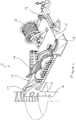
- the energy storage system 10 comprises a plurality of traction winch units 11a, 11b, 11c and 11d disposed around a purpose-build or suitable pre-existing substantially vertical subterranean shaft 12.
- Each winch unit 11a-11d comprises a steel cable 13a-13d engaged on a traction type winch system 14 and has a storage reel 15.
- Spooling guides 16 lead each cable 13a-13d from a respective winch system 14 to an associated storage reel 15.
- Respective leading sheaves 17 guide the cables 13 into the shaft 12 to support a series of composite mass bodies 20 spaced vertically one above the other in the shaft.
- a series of motor-generators 18 ( Figure 3 ) are provided to either drive the traction winches 14 in a forward direction to raise the mass bodies (20) in the shaft (12) to store potential energy, or to generate power as the winches 14 are driven in reverse by the mass bodies 20 falling in the shaft 12, as will be described below.
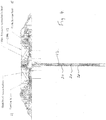
- Each mass body 20 comprises four quadrant units 21 which co-operate or nest together side by side in the shaft to form the overall composite mass body 20.
- Each quadrant unit 21 comprises an inner section 22 and an outer section 23.
- the outer surface of the outer section 23 has a plurality of hardened steel strips 24 fixed thereon.
- the inner and outer sections are clamped together by a means of bolts 25 engaging in corresponding holes 26 to define a vertical cylindrical recess or conduit 27 to accommodate a respective steel cable 13.
- the cable 13 passes through and is gripped by the conduit 27 so that the the quadrant unit 21 is clamped to the cable.
- the quadrant units 21a, 21b, 21c and 21d ( Figure 6 ) are mounted on respective cables 13a, 13b, 13c and 13d in the manner aforesaid so that the circumferentially adjacent cables are of the opposite right and left hand "lay".
- the overall arrangement ( Figure 9 ) is such that a plurality of quadrant units 21a-21d are mounted on and spaced one above the other on a respective cable 13a-13d, each set of quadrant units 21a-21d being horizontally aligned to form the composte mass bodies 20.
- the cables 13a-13d are attached to the respective traction winches 11a-11d.
- a particular example of a gravitational potential energy storage system that can be numerically demonstrated to have a gross capacity of just over 5MWh is disclosed as follows.
- a vertical shaft 12 may be constructed having a depth of 1,700 metres. This shaft 12 may be lined with suitable material to provide structural stability to the shaft wall throughout its projected lifespan, the finished internal diameter of the shaft may be 850mm.
- the total required mass being used to store a 5MWh capacity in this shaft may be in the order 1,600.00 tonnes.
- the mass units 21a-21d may be suspended in the shaft in 4 separate “lengths” each of 400 tonnes.
- Each" length is suspended on a separate steel cable, i.e. in this example there are four separate cables 13 required to suspend the total mass of 1,600 tonnes in the shaft.
- Each steel cable 13a-13d may have a diameter of 92 mm each with a minimum breaking force of 670 tonnes.
- These modular units may be cast using Lead and may be designed to be individually held in position on their respective steel cables by means of each module having been fabricated in two parts 22, 23 through a vertical cross section, the resultant two parts may bolt together around the cable in a manner that can exert perpendicular pressure upon the cable to which it is attached.
- Each modular unit 21a-21d may be manufactured so as to form, when fixed in position on the cable, a quarter segment of a vertical cylindrical section 21 that may have a total diameter of 740mm.
- Each modular unit 21 may be 2.9 metres long and fitted along its length with vertically aligned hardened steel "protective strips" 24.
- the "protective strips” may serve to isolate the Lead material of each "modular unit” from contacting with the shaft lining and also may reduce friction.
- each modular unit 21 may be 370mm in total, including tolerances which may provide an element of dynamic flexibility when moving in the vertical shaft.
- Each individual length of "modular units” which may form 400 tonnes of mass, together with its respective steel cable will be independently attached to "Traction Winch” type hoisting and lowering equipment, i.e. a total of four "Traction Winches 14a-14d may be employed in this example.
- Each "Traction Winch” may have its own cable storage reel 15 with sufficient capacity for the required function of the system.
- the four "Traction Winches” may have control systems facilitating them to operate in a synchronous manner with respect to each other, throughout the cycle of storage and regeneration of energy.
- the "modular units” 21 that comprise the "lengths" of the 400 tonne masses may accordingly be aligned horizontally in the shaft, and may be raised and lowered as one unit by the four synchronised "Traction Winches".
- a total of thirty five cylindrical sections 21 may be mounted in this manner, resulting in the total mass required of 1,600 tonnes being achieved, and culminating in the total installed length of the mass to be 427 metres overall, not accounting for any torsional elasticity that may occur in the cables.
- the total combined mass in the shaft may increase with depth due to the additional mass of the lengthening cable, load cells may detect this and the control system may react to impede the rate of descent in order to stabilise the rate at which power is being discharged.
- the modular weight system is configured in the manner described there may be a total of 413 tons of suspended mass on each length of cable at its maximum depth in the shaft, this would include the weight of the 92mm steel cable 13 at 36kg's per metre.
- Braction type winches 14a-14d Mounted at surface ground level and positioned over the shaft so as to facilitate their attachment to their respective steel cables may be four "Traction" type winches 14a-14d.
- the four "Traction Winches may be installed to have equal spacing relative to each other of 90 degrees around the shaft opening.
- a “leading roller” may be aligned at the shaft opening to guide the transfer of the cable to and from the "Traction Winch” during energy storage and dispatch.
- Load cells may be positioned in the shafts of the rollers for the acquisition of data by the control system.
- each "traction winch” may be attached to its own cable length and mass, the collective installation of “traction winches” may control the vertical movement of the total mass jointly in a synchronised mode of operation.
- Rotational steel cable 13 is composed of many cores of smaller diameter steel wire which is wound together in a manufacturing process producing either a left or right handed pitch, called a "lay". To offset any rotational forces that may be present in the cable as a result of this, the four cables may be installed with an alternating sequence of right and left handed "lays" to induce a contra torsional component during their collective operation.
- the sequence of energy storage may be initiated by raising the mass vertically in the shaft, the greater the distance that the mass is raised during this sequence can result in the greater the amount of energy stored.
- This sequence may be either partly or wholly carried out, depending on the quantity of energy being made available for storage, the maximum capacity of the system being the maximum available height/depth of the shaft.
- the physical process of raising the mass may be accomplished when each of the "Traction Winch” driving systems 14 are provided with power from a source of energy that is required to be stored.
- the type of power that may be fed to the "Traction Winch” driving systems may be any combination of electric, hydraulic etc. consequently the driving motors may be matched to be either electric or hydraulic accordingly depending on the designated medium.
- each individual “Traction Winch” may be driven with at least one electrically or hydraulically powered motor 18 coupled to appropriate gearing which may facilitate the cable being drawn around a system of sheaving rollers, this being configured specifically to exclude loss of traction of the cable during the energy storage sequence.
- the driving motors 18 may be directly coupled to the running gear of the "Traction Winches” or coupled via rotational shafting.
- All "Traction Winch” driving motors may be configured to facilitate a synchronised process of lifting the combined attached masses vertically in the shaft when they might be powered with energy from various sources for the purpose of conversion to stored potential energy.
- Each individual "Traction Winch” may be fitted with at least one electrical generator 18 or hydraulic pump.
- Each individual "Traction Winch” electrical generator or hydraulic pump component may be directly or indirectly coupled to the "Traction Winch” running gear so as to form a power take off drive for these components.
- a controlled sequence may be initiated whereby these components may be driven to produce either electrical power or pressurised fluid during the rotation of the winch.
- the production of kinetic energy during the controlled lowering of the mass 21 may be transmitted via the cables drawn around the "Traction Winch" sheave rollers thereby causing rotation and useful torque which may in turn be converted into electrical energy or hydraulic pressure.
- the driving and generating components of the "Traction Winches”, whether they may be electric or hydraulic motors, would be configured to act as dual purpose components. In this way the electric motors would also act as electrical generators and accordingly the hydraulic motors would act as hydraulic pumps.
- any electric or hydraulic combination of these components may be installed to each "Traction Winch” unit. This scenario would for example enable a "Traction Winch” during a storage time sequence to be driven hydraulically whilst, in a following time sequence, being able to reactivate stored energy electrically or vice versa.
- the storage and reactivation of energy may be processed using any form of suitable energy from any appropriate source. This may typically be alternating current, direct current, hydraulic pressure circuits and pneumatic systems.
- the system may successfully convert any type of energy which might be configured to raise the mass partly or wholly in the shaft to potential energy thereby resulting in what may effectively be an indefinite storage period without losses.
- a mechanical friction type master brake may fitted to the winch system which when applied will have sufficient capacity to indefinitely halt any downward movement of the suspended mass.
- the master brake will be subject to a "normally on” configuration to immobilise the suspended mass in the event that the control system is subjected to total power loss.
- a series of sensors may be installed to facilitate a multi-function control system which, inter alia, may be configured to detect the capacity level of the stored energy within the system at any given moment.
- the controller can then support the diversion of available energy to any vacant storage capacity by further raising the mass using this energy.
- Each "Traction Winch” may be driven by motors which are capable of functioning at various levels of power supply inputs and additionally or alternatively be provided with suitable variable gearing at their output shafts. This would facilitate the energy storage process when sources are producing minimum rates of power, while accepting a variance of the velocity at which the mass is being raised. In this way energy that has been stored with relatively low rates of power during a certain time sequence may be regenerated at a much greater rate of dispatch during a shorter time sequence.
- Each "Traction Winch” may be coupled to drive generators, pumps, or mechanical systems capable of producing regenerated power at various output levels and additionally or alternatively be provided with variable gearing to their input shafts during a sequence of energy regeneration. Power output levels may consequently be regulated in order to dispatch the stored energy capacity during a selection of time periods.
- a system to control electronic or mechanical components may be provided as a means of varying the allowable time periods for capacity discharge by varying the average descent velocity of the mass.
- the control system may regulate the average descent velocity of the mass in a selection of pre-programmed stages, or steps, or by means of a system of infinite variance between a set of maximum and minimum values. It may be commercially expedient at times, to rapidly dispatch stored energy to an electrical grid, especially during circumstances where energy may be continuously available for storage on a routine basis.
- the control system function of regulating the mass descent velocity may be accomplished by means of generator load sensing, whereby the electrical load on the generator may be increased or decreased electronically, momentarily causing additional consequent loading on the "Traction Winch" to reduce the pay-out velocity of the cable.
- the regulation of the mass descent velocity may be achieved by means of a second stage generator or pump being coupled to a power take off point on the low torque end of the "Traction Winch "output gearing.
- This second stage generator or pump may be less powerful than the primary generator or pump installations.
- This second stage component may also be regulated to provide a regenerative braking system during the stored energy retrieval sequence.
- Regenerative attenuation of the mass descent velocity may be of significant importance in terms of the overall efficiency of the system.
- the control system may be software based using analogue and digital methods to acquire data from a number of various types of sensors, encoders, transducers, load cells etc.
Landscapes
- Engineering & Computer Science (AREA)
- Chemical & Material Sciences (AREA)
- Combustion & Propulsion (AREA)
- Mechanical Engineering (AREA)
- General Engineering & Computer Science (AREA)
- Power Engineering (AREA)
- Life Sciences & Earth Sciences (AREA)
- Sustainable Development (AREA)
- Sustainable Energy (AREA)
- Other Liquid Machine Or Engine Such As Wave Power Use (AREA)
- Storing, Repeated Paying-Out, And Re-Storing Of Elongated Articles (AREA)
- Wind Motors (AREA)
Claims (10)
- Système de stockage d'énergie comprenant une pluralité de câbles (13) et une pluralité de masses à sections multiples (21) chacune suspendue à un câble respectif (13) dans un arbre (12), chacune des masses à sections multiples (21) comprenant une surface latérale longitudinale allongée s'étendant entre les surfaces d'extrémité supérieure et inférieure de celui-ci, chacun des câbles (13) étant fixé à un moyen de treuil (11) respectif par lequel la masse à sections multiples (21) respective peut être élevée dans l'arbre (12) pour stocker l'énergie potentielle, et les masses à sections multiples (21) pouvant être abaissées dans l'arbre (12) pour libérer l'énergie potentielle, caractérisé en ce que chaque masse à sections multiples (21) comprend au moins deux sections (22, 23) serrées ensemble autour du câble respectif (13), et en ce que les surfaces d'extrémité supérieure et inférieure respectives de chacune de la pluralité de masses à sections multiples (21) sont alignées horizontalement l'une avec l'autre et sont configurées pour être élevées et abaissées en synchronisme le long de l'axe longitudinal dans l'arbre (12).
- Système de stockage d'énergie selon la revendication 1, dans lequel les masses à sections multiples (21) s'emboîtent côte à côte en alignement horizontal les unes avec les autres dans l'arbre (12) pour former un corps de masse composite (20) global.
- Système de stockage d'énergie selon la revendication 2, dans lequel le corps de masse composite (20) est cylindrique et il y a quatre masses à sections multiples (21) formant chacune un quadrant du corps de masse cylindrique.
- Système de stockage d'énergie selon la revendication 3, dans lequel chaque quadrant (21) comprend une section intérieure (22) et une section extérieure (23) définissant ensemble un conduit (27) à travers lequel passe le câble (13) et dans lequel le câble (13) est saisi.
- Système de stockage d'énergie selon la revendication 3 ou 4, dans lequel des masses à sections multiples (21) adjacentes circonférentiellement sont fixées à des câbles (13) enroulés de manière opposée.
- Système de stockage d'énergie selon l'une quelconque des revendications 2 à 5, dans lequel il y a une pluralité de corps de masse composite (20) suspendus par les câbles (13) l'un au-dessus de l'autre dans l'arbre (12), chaque corps de masse étant espacé du ou des corps de masse adjacents.
- Système de stockage d'énergie selon l'une quelconque des revendications 2 à 6, dans lequel la surface extérieure de la ou de chaque masse à sections multiples (21) du corps de masse composite (20) a au moins une bande d'acier trempé (24).
- Système de stockage d'énergie selon une quelconque revendication précédente, dans lequel pour stocker l'énergie potentielle, chaque masse à sections multiples (21) est élevée par une puissance dérivée d'une source d'énergie renouvelable, par exemple l'énergie éolienne, houlomotrice ou solaire.
- Système de stockage d'énergie selon l'une quelconque des revendications 1 à 7, dans lequel pour stocker l'énergie potentielle, chaque masse à sections multiples (21) est élevée par une énergie électrique ou hydraulique.
- Système de stockage d'énergie selon une quelconque revendication précédente, dans lequel l'énergie potentielle libérée est convertie en énergie électrique ou hydraulique.
Applications Claiming Priority (2)
| Application Number | Priority Date | Filing Date | Title |
|---|---|---|---|
| IES20130066 | 2013-02-27 | ||
| PCT/EP2014/053759 WO2014131806A2 (fr) | 2013-02-27 | 2014-02-26 | Stockage d'énergie gravitationnelle potentielle |
Publications (2)
| Publication Number | Publication Date |
|---|---|
| EP2961982A2 EP2961982A2 (fr) | 2016-01-06 |
| EP2961982B1 true EP2961982B1 (fr) | 2020-12-09 |
Family
ID=51428902
Family Applications (1)
| Application Number | Title | Priority Date | Filing Date |
|---|---|---|---|
| EP14706834.0A Not-in-force EP2961982B1 (fr) | 2013-02-27 | 2014-02-26 | Stockage d'énergie gravitationnelle potentielle |
Country Status (5)
| Country | Link |
|---|---|
| US (1) | US9797384B2 (fr) |
| EP (1) | EP2961982B1 (fr) |
| AU (1) | AU2014222692B2 (fr) |
| IE (1) | IES20140050A2 (fr) |
| WO (1) | WO2014131806A2 (fr) |
Families Citing this family (10)
| Publication number | Priority date | Publication date | Assignee | Title |
|---|---|---|---|---|
| WO2017151512A1 (fr) * | 2016-02-29 | 2017-09-08 | Advanced Rail Energy Storage, L.L.C. | Système de stockage d'énergie electrique à entraînement par câble de ligne de crête |
| GB2551177A (en) * | 2016-06-09 | 2017-12-13 | Anthony Maitland Garstin Edward | Raised weight gravity generator |
| US10935005B2 (en) * | 2018-10-05 | 2021-03-02 | Ayesha Bhargava | Gravitational potential energy storage system |
| GB2578805B (en) | 2019-06-28 | 2020-12-23 | Gravitricity Ltd | Gravity-Based energy storage system |
| US12030732B2 (en) | 2019-11-07 | 2024-07-09 | Economical Energy Pty Ltd | Subterranean energy storage system |
| WO2021119765A1 (fr) * | 2019-12-19 | 2021-06-24 | Christopher Colin Stephen | Accumulation d'énergie mécanique |
| US11855457B2 (en) * | 2020-04-22 | 2023-12-26 | Terrament, Inc. | Modular gravitational energy storage systems |
| US11738781B2 (en) * | 2020-05-08 | 2023-08-29 | Advanced Rail Energy Storage, Llc | Gravitational potential energy storage systems and methods |
| WO2021231200A1 (fr) | 2020-05-11 | 2021-11-18 | Renewell Energy | Systèmes et procédés de conversion d'énergie potentielle à base de puits |
| US20260002522A1 (en) * | 2022-09-01 | 2026-01-01 | Cold Volt, Inc. | Systems and methods for the storage of energy |
Family Cites Families (11)
| Publication number | Priority date | Publication date | Assignee | Title |
|---|---|---|---|---|
| US20040178634A1 (en) * | 2003-03-13 | 2004-09-16 | Eskandr Ashraf Makrm | Power generating system of the gravity and leaf springs |
| DE102007057323A1 (de) | 2007-11-29 | 2009-06-04 | Jürgen Dipl.-Ing. Pesch | Hubspeicherkraftwerk als besondere Form eines Speicherkraftwerkes, welches der Speicherung von elektrischer Energie durch Umwandlung in potentielle Energie einer Hubmasse dient |
| US8166760B2 (en) * | 2008-02-06 | 2012-05-01 | Launchpoint Technologies, Inc. | System and method for storing energy |
| US20100025160A1 (en) * | 2008-07-31 | 2010-02-04 | Bojji Rajaram | Gravity Powered Rail, Road and Runway transportation systems |
| DE102008054229A1 (de) * | 2008-10-31 | 2010-05-12 | Zorbedo Gmbh | Verbundsystem zur Erzeugung und elektromechanischen Speicherung von elektrischer Energie |
| US8901758B1 (en) * | 2009-04-16 | 2014-12-02 | J. Douglas Nix | Gravity powered electricity generator |
| US8618680B2 (en) * | 2010-03-31 | 2013-12-31 | University Of Southern California | Spaced-apart cable modules in wellbore energy storage and retrieval |
| JP5552639B2 (ja) * | 2010-11-04 | 2014-07-16 | 北川工業株式会社 | フェライトクランプ |
| EA029730B1 (ru) * | 2010-12-24 | 2018-05-31 | ДЖИ ПАУЭР ПЛАНТС ДиэМСиСи | Система преобразования кинетической энергии в электрическую и способ генерирования электрической энергии из кинетической энергии |
| GB201111535D0 (en) | 2011-07-06 | 2011-08-17 | Fraenkel Wright Associates | Apparatus and method for electrical energy storage |
| US20150208519A1 (en) * | 2012-09-19 | 2015-07-23 | Kitagawa Industries Co., Ltd. | Ferrite clamp |
-
2014
- 2014-02-26 IE IES20140050A patent/IES20140050A2/en not_active IP Right Cessation
- 2014-02-26 AU AU2014222692A patent/AU2014222692B2/en not_active Ceased
- 2014-02-26 EP EP14706834.0A patent/EP2961982B1/fr not_active Not-in-force
- 2014-02-26 US US14/770,512 patent/US9797384B2/en not_active Expired - Fee Related
- 2014-02-26 WO PCT/EP2014/053759 patent/WO2014131806A2/fr not_active Ceased
Non-Patent Citations (1)
| Title |
|---|
| None * |
Also Published As
| Publication number | Publication date |
|---|---|
| AU2014222692A1 (en) | 2015-10-22 |
| US9797384B2 (en) | 2017-10-24 |
| US20160003224A1 (en) | 2016-01-07 |
| EP2961982A2 (fr) | 2016-01-06 |
| IES86415B2 (en) | 2014-07-16 |
| IES20140050A2 (en) | 2014-07-16 |
| AU2014222692B2 (en) | 2018-01-04 |
| WO2014131806A3 (fr) | 2014-12-24 |
| WO2014131806A2 (fr) | 2014-09-04 |
Similar Documents
| Publication | Publication Date | Title |
|---|---|---|
| EP2961982B1 (fr) | Stockage d'énergie gravitationnelle potentielle | |
| Li et al. | Potential of different forms of gravity energy storage | |
| US8618680B2 (en) | Spaced-apart cable modules in wellbore energy storage and retrieval | |
| EP2263006B1 (fr) | Système et procédé pour stocker de l énergie | |
| US9957018B1 (en) | System for wave amplifying, wave energy harnessing, and energy storage | |
| CN201843738U (zh) | 重物储电装置 | |
| CN109707577A (zh) | 一种利用滑轮组实现废弃井筒重物储能的系统和方法 | |
| CN106704121A (zh) | 高效重力储能装置 | |
| CN202789356U (zh) | 一种利用重力势能存放电的储能装置 | |
| US20200395818A1 (en) | The electric power generation system and Potential energy storage device for a power generation system | |
| GB2506133A (en) | Electrical energy storage and generating unit with suspended weight | |
| Franklin et al. | Gravity energy storage systems | |
| CN206555081U (zh) | 高效重力储能装置 | |
| Roushenas et al. | Gravity energy storage | |
| US20120161450A1 (en) | Energy Storage System | |
| US20240117793A1 (en) | A Mass Displacement Energy Storage And Electricity Generator | |
| US20240376872A1 (en) | Systems and methods for gravity energy storage | |
| CN209458068U (zh) | 一种利用滑轮组实现废弃井筒重物储能的系统 | |
| IES86415Y1 (en) | Gravitational potential energy storage | |
| Botha | Critical evaluation of large-scale gravity energy storage using linear vernier hybrid machine technology | |
| CN220769646U (zh) | 一种地下用储能装置 | |
| Vytyaz et al. | DEVELOPMENT OF A CONCEPT OF GRAVITY ENERGY STORAGE SYSTEMS BASED ON DISCONTINUED WELLS. | |
| US20250105628A1 (en) | Method - including energy storage method - for supplying energy in the vicinity of the point of consumption using regenerative energy sources, and use thereof | |
| Andújar Márquez et al. | Mechanical Storage | |
| Zhang et al. | Research Status and Prospect Analysis of Gravity Energy Storage |
Legal Events
| Date | Code | Title | Description |
|---|---|---|---|
| PUAI | Public reference made under article 153(3) epc to a published international application that has entered the european phase |
Free format text: ORIGINAL CODE: 0009012 |
|
| 17P | Request for examination filed |
Effective date: 20150924 |
|
| AK | Designated contracting states |
Kind code of ref document: A2 Designated state(s): AL AT BE BG CH CY CZ DE DK EE ES FI FR GB GR HR HU IE IS IT LI LT LU LV MC MK MT NL NO PL PT RO RS SE SI SK SM TR |
|
| AX | Request for extension of the european patent |
Extension state: BA ME |
|
| DAX | Request for extension of the european patent (deleted) | ||
| STAA | Information on the status of an ep patent application or granted ep patent |
Free format text: STATUS: EXAMINATION IS IN PROGRESS |
|
| 17Q | First examination report despatched |
Effective date: 20170206 |
|
| GRAP | Despatch of communication of intention to grant a patent |
Free format text: ORIGINAL CODE: EPIDOSNIGR1 |
|
| STAA | Information on the status of an ep patent application or granted ep patent |
Free format text: STATUS: GRANT OF PATENT IS INTENDED |
|
| INTG | Intention to grant announced |
Effective date: 20200624 |
|
| GRAS | Grant fee paid |
Free format text: ORIGINAL CODE: EPIDOSNIGR3 |
|
| GRAA | (expected) grant |
Free format text: ORIGINAL CODE: 0009210 |
|
| STAA | Information on the status of an ep patent application or granted ep patent |
Free format text: STATUS: THE PATENT HAS BEEN GRANTED |
|
| AK | Designated contracting states |
Kind code of ref document: B1 Designated state(s): AL AT BE BG CH CY CZ DE DK EE ES FI FR GB GR HR HU IE IS IT LI LT LU LV MC MK MT NL NO PL PT RO RS SE SI SK SM TR |
|
| REG | Reference to a national code |
Ref country code: GB Ref legal event code: FG4D |
|
| REG | Reference to a national code |
Ref country code: AT Ref legal event code: REF Ref document number: 1343714 Country of ref document: AT Kind code of ref document: T Effective date: 20201215 Ref country code: CH Ref legal event code: EP |
|
| REG | Reference to a national code |
Ref country code: DE Ref legal event code: R096 Ref document number: 602014073144 Country of ref document: DE |
|
| REG | Reference to a national code |
Ref country code: IE Ref legal event code: FG4D |
|
| PG25 | Lapsed in a contracting state [announced via postgrant information from national office to epo] |
Ref country code: RS Free format text: LAPSE BECAUSE OF FAILURE TO SUBMIT A TRANSLATION OF THE DESCRIPTION OR TO PAY THE FEE WITHIN THE PRESCRIBED TIME-LIMIT Effective date: 20201209 Ref country code: FI Free format text: LAPSE BECAUSE OF FAILURE TO SUBMIT A TRANSLATION OF THE DESCRIPTION OR TO PAY THE FEE WITHIN THE PRESCRIBED TIME-LIMIT Effective date: 20201209 Ref country code: NO Free format text: LAPSE BECAUSE OF FAILURE TO SUBMIT A TRANSLATION OF THE DESCRIPTION OR TO PAY THE FEE WITHIN THE PRESCRIBED TIME-LIMIT Effective date: 20210309 Ref country code: GR Free format text: LAPSE BECAUSE OF FAILURE TO SUBMIT A TRANSLATION OF THE DESCRIPTION OR TO PAY THE FEE WITHIN THE PRESCRIBED TIME-LIMIT Effective date: 20210310 |
|
| REG | Reference to a national code |
Ref country code: AT Ref legal event code: MK05 Ref document number: 1343714 Country of ref document: AT Kind code of ref document: T Effective date: 20201209 |
|
| PG25 | Lapsed in a contracting state [announced via postgrant information from national office to epo] |
Ref country code: BG Free format text: LAPSE BECAUSE OF FAILURE TO SUBMIT A TRANSLATION OF THE DESCRIPTION OR TO PAY THE FEE WITHIN THE PRESCRIBED TIME-LIMIT Effective date: 20210309 Ref country code: SE Free format text: LAPSE BECAUSE OF FAILURE TO SUBMIT A TRANSLATION OF THE DESCRIPTION OR TO PAY THE FEE WITHIN THE PRESCRIBED TIME-LIMIT Effective date: 20201209 Ref country code: LV Free format text: LAPSE BECAUSE OF FAILURE TO SUBMIT A TRANSLATION OF THE DESCRIPTION OR TO PAY THE FEE WITHIN THE PRESCRIBED TIME-LIMIT Effective date: 20201209 |
|
| REG | Reference to a national code |
Ref country code: NL Ref legal event code: MP Effective date: 20201209 |
|
| PG25 | Lapsed in a contracting state [announced via postgrant information from national office to epo] |
Ref country code: NL Free format text: LAPSE BECAUSE OF FAILURE TO SUBMIT A TRANSLATION OF THE DESCRIPTION OR TO PAY THE FEE WITHIN THE PRESCRIBED TIME-LIMIT Effective date: 20201209 Ref country code: HR Free format text: LAPSE BECAUSE OF FAILURE TO SUBMIT A TRANSLATION OF THE DESCRIPTION OR TO PAY THE FEE WITHIN THE PRESCRIBED TIME-LIMIT Effective date: 20201209 |
|
| REG | Reference to a national code |
Ref country code: LT Ref legal event code: MG9D |
|
| PG25 | Lapsed in a contracting state [announced via postgrant information from national office to epo] |
Ref country code: SK Free format text: LAPSE BECAUSE OF FAILURE TO SUBMIT A TRANSLATION OF THE DESCRIPTION OR TO PAY THE FEE WITHIN THE PRESCRIBED TIME-LIMIT Effective date: 20201209 Ref country code: PT Free format text: LAPSE BECAUSE OF FAILURE TO SUBMIT A TRANSLATION OF THE DESCRIPTION OR TO PAY THE FEE WITHIN THE PRESCRIBED TIME-LIMIT Effective date: 20210409 Ref country code: RO Free format text: LAPSE BECAUSE OF FAILURE TO SUBMIT A TRANSLATION OF THE DESCRIPTION OR TO PAY THE FEE WITHIN THE PRESCRIBED TIME-LIMIT Effective date: 20201209 Ref country code: LT Free format text: LAPSE BECAUSE OF FAILURE TO SUBMIT A TRANSLATION OF THE DESCRIPTION OR TO PAY THE FEE WITHIN THE PRESCRIBED TIME-LIMIT Effective date: 20201209 Ref country code: EE Free format text: LAPSE BECAUSE OF FAILURE TO SUBMIT A TRANSLATION OF THE DESCRIPTION OR TO PAY THE FEE WITHIN THE PRESCRIBED TIME-LIMIT Effective date: 20201209 Ref country code: CZ Free format text: LAPSE BECAUSE OF FAILURE TO SUBMIT A TRANSLATION OF THE DESCRIPTION OR TO PAY THE FEE WITHIN THE PRESCRIBED TIME-LIMIT Effective date: 20201209 Ref country code: SM Free format text: LAPSE BECAUSE OF FAILURE TO SUBMIT A TRANSLATION OF THE DESCRIPTION OR TO PAY THE FEE WITHIN THE PRESCRIBED TIME-LIMIT Effective date: 20201209 |
|
| PG25 | Lapsed in a contracting state [announced via postgrant information from national office to epo] |
Ref country code: PL Free format text: LAPSE BECAUSE OF FAILURE TO SUBMIT A TRANSLATION OF THE DESCRIPTION OR TO PAY THE FEE WITHIN THE PRESCRIBED TIME-LIMIT Effective date: 20201209 Ref country code: AT Free format text: LAPSE BECAUSE OF FAILURE TO SUBMIT A TRANSLATION OF THE DESCRIPTION OR TO PAY THE FEE WITHIN THE PRESCRIBED TIME-LIMIT Effective date: 20201209 |
|
| REG | Reference to a national code |
Ref country code: DE Ref legal event code: R119 Ref document number: 602014073144 Country of ref document: DE |
|
| PG25 | Lapsed in a contracting state [announced via postgrant information from national office to epo] |
Ref country code: MC Free format text: LAPSE BECAUSE OF FAILURE TO SUBMIT A TRANSLATION OF THE DESCRIPTION OR TO PAY THE FEE WITHIN THE PRESCRIBED TIME-LIMIT Effective date: 20201209 Ref country code: IS Free format text: LAPSE BECAUSE OF FAILURE TO SUBMIT A TRANSLATION OF THE DESCRIPTION OR TO PAY THE FEE WITHIN THE PRESCRIBED TIME-LIMIT Effective date: 20210409 |
|
| PLBE | No opposition filed within time limit |
Free format text: ORIGINAL CODE: 0009261 |
|
| STAA | Information on the status of an ep patent application or granted ep patent |
Free format text: STATUS: NO OPPOSITION FILED WITHIN TIME LIMIT |
|
| REG | Reference to a national code |
Ref country code: BE Ref legal event code: MM Effective date: 20210228 |
|
| PG25 | Lapsed in a contracting state [announced via postgrant information from national office to epo] |
Ref country code: LI Free format text: LAPSE BECAUSE OF NON-PAYMENT OF DUE FEES Effective date: 20210228 Ref country code: LU Free format text: LAPSE BECAUSE OF NON-PAYMENT OF DUE FEES Effective date: 20210226 Ref country code: AL Free format text: LAPSE BECAUSE OF FAILURE TO SUBMIT A TRANSLATION OF THE DESCRIPTION OR TO PAY THE FEE WITHIN THE PRESCRIBED TIME-LIMIT Effective date: 20201209 Ref country code: CH Free format text: LAPSE BECAUSE OF NON-PAYMENT OF DUE FEES Effective date: 20210228 Ref country code: IT Free format text: LAPSE BECAUSE OF FAILURE TO SUBMIT A TRANSLATION OF THE DESCRIPTION OR TO PAY THE FEE WITHIN THE PRESCRIBED TIME-LIMIT Effective date: 20201209 |
|
| 26N | No opposition filed |
Effective date: 20210910 |
|
| PG25 | Lapsed in a contracting state [announced via postgrant information from national office to epo] |
Ref country code: SI Free format text: LAPSE BECAUSE OF FAILURE TO SUBMIT A TRANSLATION OF THE DESCRIPTION OR TO PAY THE FEE WITHIN THE PRESCRIBED TIME-LIMIT Effective date: 20201209 Ref country code: DK Free format text: LAPSE BECAUSE OF FAILURE TO SUBMIT A TRANSLATION OF THE DESCRIPTION OR TO PAY THE FEE WITHIN THE PRESCRIBED TIME-LIMIT Effective date: 20201209 Ref country code: ES Free format text: LAPSE BECAUSE OF FAILURE TO SUBMIT A TRANSLATION OF THE DESCRIPTION OR TO PAY THE FEE WITHIN THE PRESCRIBED TIME-LIMIT Effective date: 20201209 |
|
| PG25 | Lapsed in a contracting state [announced via postgrant information from national office to epo] |
Ref country code: DE Free format text: LAPSE BECAUSE OF NON-PAYMENT OF DUE FEES Effective date: 20210901 |
|
| PG25 | Lapsed in a contracting state [announced via postgrant information from national office to epo] |
Ref country code: IS Free format text: LAPSE BECAUSE OF FAILURE TO SUBMIT A TRANSLATION OF THE DESCRIPTION OR TO PAY THE FEE WITHIN THE PRESCRIBED TIME-LIMIT Effective date: 20210409 |
|
| PG25 | Lapsed in a contracting state [announced via postgrant information from national office to epo] |
Ref country code: BE Free format text: LAPSE BECAUSE OF NON-PAYMENT OF DUE FEES Effective date: 20210228 |
|
| PG25 | Lapsed in a contracting state [announced via postgrant information from national office to epo] |
Ref country code: HU Free format text: LAPSE BECAUSE OF FAILURE TO SUBMIT A TRANSLATION OF THE DESCRIPTION OR TO PAY THE FEE WITHIN THE PRESCRIBED TIME-LIMIT; INVALID AB INITIO Effective date: 20140226 |
|
| PG25 | Lapsed in a contracting state [announced via postgrant information from national office to epo] |
Ref country code: CY Free format text: LAPSE BECAUSE OF FAILURE TO SUBMIT A TRANSLATION OF THE DESCRIPTION OR TO PAY THE FEE WITHIN THE PRESCRIBED TIME-LIMIT Effective date: 20201209 |
|
| PGFP | Annual fee paid to national office [announced via postgrant information from national office to epo] |
Ref country code: IE Payment date: 20240202 Year of fee payment: 11 |
|
| PG25 | Lapsed in a contracting state [announced via postgrant information from national office to epo] |
Ref country code: MK Free format text: LAPSE BECAUSE OF FAILURE TO SUBMIT A TRANSLATION OF THE DESCRIPTION OR TO PAY THE FEE WITHIN THE PRESCRIBED TIME-LIMIT Effective date: 20201209 |
|
| PGFP | Annual fee paid to national office [announced via postgrant information from national office to epo] |
Ref country code: GB Payment date: 20240213 Year of fee payment: 11 |
|
| PGFP | Annual fee paid to national office [announced via postgrant information from national office to epo] |
Ref country code: FR Payment date: 20240222 Year of fee payment: 11 |
|
| PG25 | Lapsed in a contracting state [announced via postgrant information from national office to epo] |
Ref country code: MT Free format text: LAPSE BECAUSE OF FAILURE TO SUBMIT A TRANSLATION OF THE DESCRIPTION OR TO PAY THE FEE WITHIN THE PRESCRIBED TIME-LIMIT Effective date: 20201209 |
|
| GBPC | Gb: european patent ceased through non-payment of renewal fee |
Effective date: 20250226 |
|
| PG25 | Lapsed in a contracting state [announced via postgrant information from national office to epo] |
Ref country code: TR Free format text: LAPSE BECAUSE OF FAILURE TO SUBMIT A TRANSLATION OF THE DESCRIPTION OR TO PAY THE FEE WITHIN THE PRESCRIBED TIME-LIMIT Effective date: 20201209 |
|
| PG25 | Lapsed in a contracting state [announced via postgrant information from national office to epo] |
Ref country code: GB Free format text: LAPSE BECAUSE OF NON-PAYMENT OF DUE FEES Effective date: 20250226 |
|
| PG25 | Lapsed in a contracting state [announced via postgrant information from national office to epo] |
Ref country code: FR Free format text: LAPSE BECAUSE OF NON-PAYMENT OF DUE FEES Effective date: 20250228 |
|
| PG25 | Lapsed in a contracting state [announced via postgrant information from national office to epo] |
Ref country code: IE Free format text: LAPSE BECAUSE OF NON-PAYMENT OF DUE FEES Effective date: 20250226 |