EP2962587A1 - Sportschuh - Google Patents
Sportschuh Download PDFInfo
- Publication number
- EP2962587A1 EP2962587A1 EP15001876.0A EP15001876A EP2962587A1 EP 2962587 A1 EP2962587 A1 EP 2962587A1 EP 15001876 A EP15001876 A EP 15001876A EP 2962587 A1 EP2962587 A1 EP 2962587A1
- Authority
- EP
- European Patent Office
- Prior art keywords
- shoe
- guide element
- base
- intermediate guide
- longitudinal bar
- Prior art date
- Legal status (The legal status is an assumption and is not a legal conclusion. Google has not performed a legal analysis and makes no representation as to the accuracy of the status listed.)
- Withdrawn
Links
- 210000001872 metatarsal bone Anatomy 0.000 claims abstract description 17
- 230000000717 retained effect Effects 0.000 claims abstract description 3
- 210000002683 foot Anatomy 0.000 description 10
- 230000005540 biological transmission Effects 0.000 description 6
- 238000000034 method Methods 0.000 description 5
- 230000008447 perception Effects 0.000 description 5
- 230000001953 sensory effect Effects 0.000 description 5
- 238000006243 chemical reaction Methods 0.000 description 4
- 230000000670 limiting effect Effects 0.000 description 3
- 239000004698 Polyethylene Substances 0.000 description 2
- 238000005452 bending Methods 0.000 description 2
- 238000012423 maintenance Methods 0.000 description 2
- 239000000463 material Substances 0.000 description 2
- 238000005457 optimization Methods 0.000 description 2
- -1 polyethylene Polymers 0.000 description 2
- 229920000573 polyethylene Polymers 0.000 description 2
- 229920002635 polyurethane Polymers 0.000 description 2
- 239000004814 polyurethane Substances 0.000 description 2
- 229920002994 synthetic fiber Polymers 0.000 description 2
- 210000003371 toe Anatomy 0.000 description 2
- 239000000470 constituent Substances 0.000 description 1
- 239000000835 fiber Substances 0.000 description 1
- 230000036961 partial effect Effects 0.000 description 1
- 230000002829 reductive effect Effects 0.000 description 1
- 229920005989 resin Polymers 0.000 description 1
- 239000011347 resin Substances 0.000 description 1
- 230000002441 reversible effect Effects 0.000 description 1
- 239000012815 thermoplastic material Substances 0.000 description 1
Images




Classifications
-
- A—HUMAN NECESSITIES
- A43—FOOTWEAR
- A43B—CHARACTERISTIC FEATURES OF FOOTWEAR; PARTS OF FOOTWEAR
- A43B5/00—Footwear for sporting purposes
- A43B5/04—Ski or like boots
- A43B5/0411—Ski or like boots for cross-country
- A43B5/0413—Adaptations for soles or accessories associated with soles for cross-country bindings
-
- A—HUMAN NECESSITIES
- A43—FOOTWEAR
- A43B—CHARACTERISTIC FEATURES OF FOOTWEAR; PARTS OF FOOTWEAR
- A43B5/00—Footwear for sporting purposes
- A43B5/04—Ski or like boots
- A43B5/0427—Ski or like boots characterised by type or construction details
- A43B5/047—Ski or like boots characterised by type or construction details provided with means to improve walking with the skiboot
-
- A—HUMAN NECESSITIES
- A43—FOOTWEAR
- A43B—CHARACTERISTIC FEATURES OF FOOTWEAR; PARTS OF FOOTWEAR
- A43B5/00—Footwear for sporting purposes
- A43B5/04—Ski or like boots
- A43B5/0492—Telemark boots
- A43B5/0494—Adaptations for soles or accessories associated with soles for telemark bindings
-
- A—HUMAN NECESSITIES
- A43—FOOTWEAR
- A43B—CHARACTERISTIC FEATURES OF FOOTWEAR; PARTS OF FOOTWEAR
- A43B5/00—Footwear for sporting purposes
- A43B5/04—Ski or like boots
- A43B5/0496—Ski or like boots boots for touring or hiking skis
Definitions
- the invention relates to a shoe designed to be held reversibly to a sports gliding device, and more particularly to a shoe intended for the practice of a snow sport.
- Such shoes can be used in areas such as cross-country skiing, ski touring, telemark, snowshoeing, or other.
- a shoe of this family generally comprises an outer sole, a rod and an attachment element, the latter being provided to cooperate with a locking mechanism itself intended to be subject to the machine.
- the hooking element and the locking mechanism are a hooking means which, very often, is provided to hold the boot on the machine in a reversible manner.
- each locking mechanism In the field of cross-country skiing, it is usual for each locking mechanism to either hold a shoe or release it. This allows the choice to drive the skis or walk.
- the foot can unfold, or flex relative to the lower leg, which allows the guidance of the ski when in contact with the ground, for example in a sliding phase or in a support phase, or controlling the position of the ski when it is away from the ground, for example in a return phase of the ski forward after a thrust with back support.
- the observed phenomena are variable according to the users, because they have different weights, different sizes, different levels of practice, different driving styles.
- the conditions of use may vary depending on factors such as snow quality, inclination of the ground, or other. It generally appears that a shoe of given structure is not necessarily adapted to any user, or that if it is in some cases it is not in all cases. This is to say that a shoe is generally not versatile enough in the sense that it does not satisfy a user in all possible conditions of use.
- the invention generally seeks to improve a shoe. More specifically, the invention seeks to improve the transmission of driving pulses, the return of the reactions of the ground or of a machine, or the perception of sensory information. More specifically, the invention seeks to optimize the driving efficiency and reduce the fatigue of a user.
- the invention also wishes to make the shoe more versatile, that is to say, to make it suitable for the largest number of users. In particular, any user should obtain maximum efficiency in the transmission of driving impulses or in the perception of sensory information related to driving, regardless of the conditions of use.
- the invention proposes a shoe designed to be held reversibly to a sports machine, the shoe comprising a base, which extends in length from a rear end to a front end, in width between a lateral edge and a medial edge, and in height between a face of cooperation with the machine and an inner face, the base having, from the rear end to the front end, a rear zone, a central zone, a metatarsal zone, and a front zone, the shoe comprising a front guide element, located in the front zone on the side of the cooperation face.
- the shoe according to the invention is characterized in that it comprises an intermediate guide element, which is situated at least partly in the metatarsal zone on the side of the cooperation face, and in that it comprises a means for removably connecting the intermediate guide member with respect to the base.
- the structure of the shoe according to the invention allows the introduction or removal of the intermediate guide element.
- a change in the intermediate guide element in some cases can change the mechanical characteristics of the shoe, at the base. For example, changing the stiffness of the element changes the longitudinal flexural characteristics of the shoe at the base.
- the invention allows the optimization of mechanical properties of the shoe, such as the bending ability at the base along a transverse axis.
- the user can walk or drive a machine by performing natural movements, such as unwinding or flexing the foot, with particularly limited discomfort, or even without embarrassment.
- the invention improves the transmission of driving pulses, the return of the reactions of the ground or of a machine, or the perception of sensory information.
- the driving performance is better than with a shoe according to the prior art.
- the user is less tired, and his performance is better.
- the shoe according to the invention is more versatile because it can be better adapted to the specificities or needs of a user.
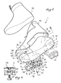
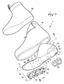
- Figures 1 to 8 it is with the help of Figures 1 to 8 that is presented the first form.
- a shoe 1 designed to accommodate the foot of the user. It will be seen later that the shoe can be held reversibly to a sports machine, for example a ski, which is not shown here.
- the shoe 1 comprises a base 2, which extends in length from a rear end 3 to a front end 4, in width between a lateral edge 5 and a medial edge 6, and in height between a face 7 with the machine and an inner face 8.
- the cooperation face 7 can, in unrepresented configurations, come into contact with the machine directly or indirectly.
- an intermediate element such as a retaining device and / or an interface plate, is placed between the boot and the machine.
- the inner face 8, as for it and as will be better understood later, can come into contact with the foot of the user directly or indirectly.
- the base 2 has, from the rear end 3 to the front end 4, a rear zone 11, provided to come opposite the heel of the foot, a central zone 12 , which comes next to the arch, a metatarsal area 13, which is next to the metatarsal, and a front zone 14, which comes next to the toes.
- the shoe also comprises a front guide element 15, located in the front zone 14 on the side of the cooperation face 7.
- the front guide member 15 here comprises a first longitudinal bar 16 and a second longitudinal bar 17, and a bridge 18 which connects to one another the first longitudinal bar and the second longitudinal bar. It will be seen better after the front guide member 15 is connected to the base 2 removably, for example by means of one or more screw-nut devices.
- the shoe 1 comprises an intermediate guide element 21, which is located at least partly in the metatarsal area 13 on the side of the cooperation face 7, and the shoe comprises a removable connecting means 22 of the intermediate guide element with respect to the base 2.
- the intermediate guide element 21 can be placed on the base, or removed. It is therefore possible to replace this element with another. Replacement can take place in case of wear, or to change the mechanical characteristics. This means that a change of the intermediate guide element in some cases can change the mechanical characteristics of the shoe, at the base 2. For example, by changing the stiffness of the element 21, the stiffness is changed at the base level.
- the user has several guide elements, he can select the one that suits him for a given use. It thus optimizes the mechanical properties of the shoe, as the ability to flex the base along a transverse axis. As a result he can walk or drive a craft by performing natural movements, such as unwinding or flexing the foot, with a particularly reduced discomfort, or even without embarrassment. The driving performance is improved.
- the intermediate guide element 21 comprises a first longitudinal bar 23 and a second longitudinal bar 24, as well as a bridge 25 which connects the first longitudinal bar 23 and the second longitudinal bar 24 to each other.
- 23, 24 and the bridge 25 form a single piece, made for example using a synthetic material. Polyurethane, polyethylene, or any other equivalent material may be suitable.
- the space 26 between the bars 23, 24 delimits a longitudinal guiding groove, designed to cooperate with a protrusion disposed optionally on the ski or on the intermediate element between the ski and the boot.
- the guide groove 26 guides the base 2 in the direction of the length of the shoe.
- the intermediate guide member comprises two or more longitudinal bars, excluding any bridge. Each bar is then secured as it is at the base.
- Each longitudinal bar 23, 24 of the intermediate guide member 21 has notches 26, only one is designated in each figure concerned for the sake of clarity.
- the cuts can be of different shapes.
- the notches open transversely and opposite the base 2.
- the bridge 25 takes up against the base 2, or near the base 2. This provision promotes a longitudinal flexion, that is to say by relative to a transverse axis parallel to the base, the intermediate guide element 21.
- the notches 26 are here aligned in two transversely: a notch of a bar 23 is opposite a notch of the other bar 24, for an optimization of the bending ability previously mentioned.
- the detachable connection means 22 of the intermediate guide element 21 relative to the base 2 comprises at least one screw-nut device. Only one of these is detailed, to show that it comprises a screw 27 and a nut 28.
- the screw 27 is placed on the side of the cooperation face 7 by passing through the intermediate guide element 21 and the base 2, while the nut 28 takes place on the side of the inner face 8 of the base.
- the intermediate guide element 21 has an orifice 29, and the base 2 has an orifice 30.
- the removable connecting means 22 comprises six screw-nut devices.
- the shoe 1 comprises a removable connection means 32 of the front guide member 15 with respect to the base 2.
- the removable connection means 32 of the front guide element It also includes at least one screw-and-nut device. And again it is for example used a screw 27 and a nut 28, set up as seen above.
- the detachable connection means 22 and the detachable connection means 32 have common elements, namely two screws 27 and two nuts 28.
- the screws and nuts in question simultaneously hold the intermediate guide element 21 and the front guide member 15.
- Each element 21, 15 may be more or less rigid, to adjust the ability of the shoe 1 to flex longitudinally, particularly at the base 2. This allows for example to adapt the shoe to the level of practice of a user .
- the boot 1 comprises, if desired, a wedge 33 disposed between the intermediate guide element 21 and the base 2.
- the wedge 33 is constituted by a plate, made for example of synthetic material, such as polyurethane, polyethylene, a layer of resin or thermoplastic material reinforced with fibers or any other charge, or the like.
- the shim 33 is retained between the intermediate guide element 21 and the base 2, by the action of the removable connection means 22, that is to say here by the action of screw-nut devices.
- the wedge 33 has orifices 34 for the passage of the screws 27.
- the shim 33 extends only facing the intermediate guide element 21. This makes it possible to adjust the rigidity of the boot, with regard to its longitudinal flexion at the base 2, in the metatarsal zone 13.
- the shim 33 extends opposite the intermediate guide element 21 and facing the element of It then follows that the adjustment of the rigidity of the shoe is done in the metatarsal zone 13 and in the front zone 14.
- first longitudinal bar 16 of the front guide member 15 is aligned with the first longitudinal bar 23 of the intermediate guide member 21, and that the second longitudinal bar 17 of the front guide member 15 is aligned with the second longitudinal bar 24 of the intermediate guide element 21.
- This allows a longitudinal guide of the base 2 at both the front zone 14 and the metatarsal zone 13.
- the boot 1 comprises means for positioning the intermediate guide element 21 with respect to the front guide element 15. This is to guarantee the relative alignment of the guide elements 21, 15.
- the positioning means by the action of the positioning means, the first bar 16 of the front element 15 is aligned with the first bar 23 of the intermediate element 21, and the second bar 17 of the front element 15 is aligned with the second bar 24 of the intermediate element 21.
- the positioning means of the intermediate guide element 21 with respect to the front guide element 15 has a stop 35 on the intermediate guide element 21 and a stop 36 on the intermediate guide element 21.
- the stops 35, 36 are shaped to bear against each other.
- the stop 35 of the intermediate guide element 21 is fragmented, and the stop 36 of the front guide element 15 is fragmented.
- the stop 35 comprises a tongue 41 at the first longitudinal bar 23, and a tongue 42 at the second longitudinal bar 24.
- the stop 36 comprises a tongue 43 at the level of the first longitudinal bar 16, and a tongue 44 at the second longitudinal bar 17. It is observed that the tabs 41, 43 of the first bars 23, 16 and the tabs 42, 44 of the second bars 24, 17 are superimposed. In fact, each tongue 41, 42, 42, 44 is a thinned end of a bar. This makes it easy to apply one to the contact of the other.
- the structure of the shoe 1 is such that in the rear zone 11 and in the central zone 12 the base 2 is extended, on the side of the inner face 8, by a lateral wall 51, a rear wall 52 and a medial wall 53, to form a rear footwear, and such that, in the front zone 14, the base 2 is extended, on the side of the inner face 8, by a side wall 54, a front wall 55 and a medial wall 56, for forming a front footwear volume, a transverse slot 57 remaining between the rear and front footwear, and still such that a flexible cover 58 covers the front footwear volume, the transverse slot 57, and the rear footwear volume.
- the shoe 1 comprises a shoe 59, which can be made by any technique known to a person skilled in the art.
- the slipper 59 takes place against the inner face 8 of the base 2, being covered by the flexible cover 58.
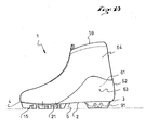
- FIG. 9 there is a shoe 1, with a base 2, a rear end 3, a front end 4, a lateral edge 5, a medial edge 6, a cooperation face 7 and an inner face 8.
- a rear zone 11 There is also a rear zone 11 , a central zone 12, a metatarsal zone 13 and a front zone 14, as well as a front guide element 15 and an intermediate guide element 21.
- the base 2 is extended, on the side of the inner face 8, by a side wall 61, a rear wall 62 and a medial wall 63, to form a rear footwear volume, the base 2 having the appearance of a blade forward 4, and it is also that the shoe 1 comprises a flexible rod 64 affixed to the base being nested in the rear footwear volume.
- a liner 59 is inserted into the rod 64.
- the liner may be removable, that is to say, able to be removed from the rod.
- the shoe can alternatively be secured permanently to the stem by any appropriate technique, such as a collage, or other.
- the intermediate guide element 21 and the front guide element 15 form a single piece, which is removable, that is to say, separable from the base 2.
- the intermediate guide element 21 and the front guide element 15 form a single piece, which is removable, that is to say, separable from the base 2.
- the shoe 1 comprises a detachable connecting means of the one-piece piece relative to the base 2.
- the intermediate guide member 21 comprises a first longitudinal bar 86, a second longitudinal bar 87 and a third longitudinal bar 88, as well as a bridge 89 which connects together the first longitudinal bar 86, the second longitudinal bar 87, and the third longitudinal bar 88.
- This structure allows the boot 1 to be guided longitudinally, via the intermediate guide element 21, by two projections disposed at will on the ski or on the intermediate element between the ski and the shoe.
- the guide elements 15, 21 have been shown associated with a base 2, it can alternatively be provided that these elements are associated with a sole assembly consisting of one or more layers, the sole assembly being secured to a rod for to form a shoe.
- the shoe 1 comprises a rear guide element 91, which is, optionally, removable or non-removable.
- the boot 1 comprises a hooking means provided to cooperate with a ski retainer.
- the attachment means here comprises, by way of non-limiting example, a first attachment element 92 and a second attachment element 93, knowing that only one can be provided.
- Each element 92, 93 has a subdivision of circular section. It is observed that at least one fastening element 92, 93 is secured to the front guide element 15. The fastening element extends between the bars 16, 17, and is set back from a surface the guide member 15 provided to bear on the ground. In other words, at least one subdivision of one or both fastening elements is closer to the base 2 than are the ends of the studs materialized by the notches 26.
Landscapes
- Health & Medical Sciences (AREA)
- General Health & Medical Sciences (AREA)
- Physical Education & Sports Medicine (AREA)
- Footwear And Its Accessory, Manufacturing Method And Apparatuses (AREA)
Applications Claiming Priority (1)
| Application Number | Priority Date | Filing Date | Title |
|---|---|---|---|
| FR1401496A FR3023131B1 (fr) | 2014-07-03 | 2014-07-03 | Chaussure de sport |
Publications (1)
| Publication Number | Publication Date |
|---|---|
| EP2962587A1 true EP2962587A1 (de) | 2016-01-06 |
Family
ID=51483480
Family Applications (1)
| Application Number | Title | Priority Date | Filing Date |
|---|---|---|---|
| EP15001876.0A Withdrawn EP2962587A1 (de) | 2014-07-03 | 2015-06-25 | Sportschuh |
Country Status (3)
| Country | Link |
|---|---|
| EP (1) | EP2962587A1 (de) |
| FR (1) | FR3023131B1 (de) |
| RU (1) | RU2015125524A (de) |
Cited By (2)
| Publication number | Priority date | Publication date | Assignee | Title |
|---|---|---|---|---|
| EP3659456A1 (de) * | 2018-11-27 | 2020-06-03 | Fischer Sports GmbH | Sohlenaufbau für einen sportschuh |
| CN115813082A (zh) * | 2022-12-12 | 2023-03-21 | 张宸瑞 | 一种有固定装置的鞋底 |
Citations (3)
| Publication number | Priority date | Publication date | Assignee | Title |
|---|---|---|---|---|
| EP0530764A2 (de) * | 1991-09-06 | 1993-03-10 | NORDICA S.p.A | Sohle, insbesondere für Skischuhe |
| US20140115929A1 (en) * | 2012-10-26 | 2014-05-01 | John Erik Svensson | Base for a ski boot and ski boot incorporating such a base |
| EP2737815A2 (de) * | 2012-11-30 | 2014-06-04 | Salomon S.A.S. | Anpassbarer Sportschuh |
-
2014
- 2014-07-03 FR FR1401496A patent/FR3023131B1/fr not_active Expired - Fee Related
-
2015
- 2015-06-25 EP EP15001876.0A patent/EP2962587A1/de not_active Withdrawn
- 2015-06-26 RU RU2015125524A patent/RU2015125524A/ru not_active Application Discontinuation
Patent Citations (3)
| Publication number | Priority date | Publication date | Assignee | Title |
|---|---|---|---|---|
| EP0530764A2 (de) * | 1991-09-06 | 1993-03-10 | NORDICA S.p.A | Sohle, insbesondere für Skischuhe |
| US20140115929A1 (en) * | 2012-10-26 | 2014-05-01 | John Erik Svensson | Base for a ski boot and ski boot incorporating such a base |
| EP2737815A2 (de) * | 2012-11-30 | 2014-06-04 | Salomon S.A.S. | Anpassbarer Sportschuh |
Cited By (3)
| Publication number | Priority date | Publication date | Assignee | Title |
|---|---|---|---|---|
| EP3659456A1 (de) * | 2018-11-27 | 2020-06-03 | Fischer Sports GmbH | Sohlenaufbau für einen sportschuh |
| WO2020109293A1 (de) * | 2018-11-27 | 2020-06-04 | Fischer Sports Gmbh | Sohlenaufbau für einen sportschuh |
| CN115813082A (zh) * | 2022-12-12 | 2023-03-21 | 张宸瑞 | 一种有固定装置的鞋底 |
Also Published As
| Publication number | Publication date |
|---|---|
| RU2015125524A (ru) | 2017-01-10 |
| FR3023131A1 (fr) | 2016-01-08 |
| FR3023131B1 (fr) | 2018-04-13 |
Similar Documents
| Publication | Publication Date | Title |
|---|---|---|
| EP2465371B1 (de) | Sportschuh | |
| EP2347666B1 (de) | Schuh mit verbesserter Sohle | |
| EP2198729B1 (de) | Schuh mit verbessertem Schuhboden | |
| EP0787440B1 (de) | Sohle für Sportschuh | |
| EP1132015A1 (de) | Baueinheit aus Sohle und Keil | |
| EP2532261A2 (de) | Schuh mit verbessertem Schaft | |
| EP0548475A1 (de) | Mehrschichtige Sportschuhsohle | |
| FR2923362A1 (fr) | Chaussure a serrage de tige ameliore | |
| WO2012114002A2 (fr) | Chaussure destinée à la pratique d'un sport de glisse sur neige, ou à la marche | |
| FR2774870A1 (fr) | Chaussure comportant un insert grind | |
| EP2353417A1 (de) | Schuh mit verbesserter Sohle | |
| EP3195748B1 (de) | Sohle eines langlauf-skischuhs | |
| EP2737815B1 (de) | Anpassbarer Sportschuh | |
| EP0933100A1 (de) | Bindung für einen Schuh an einem Snowboard | |
| EP2082658A1 (de) | Schuh, der einen flachen und einen hohen Teil umfasst | |
| EP0796570A1 (de) | Snowboardstriefel | |
| EP2374513B1 (de) | Vorrichtung zur Aufnahme eines Fußes oder eines Schuhs auf einem Gleitgerät | |
| EP2962587A1 (de) | Sportschuh | |
| FR2537011A1 (fr) | Fixation d'une chaussure a un ski | |
| EP2606760A1 (de) | Schuhelement, das mit einer verbesserten Festziehvorrichtung ausgestattet ist | |
| EP2989917B1 (de) | Sportschuh | |
| FR2656775A1 (fr) | Chaussure de ski en matiere plastique. | |
| EP3195749A1 (de) | Schuhwerk für das ausüben eines gleitsports | |
| CA2834645A1 (fr) | Chaussure de sport adaptable | |
| EP2752124A1 (de) | Sportschuh mit einstellbarer Biegefestigkeit |
Legal Events
| Date | Code | Title | Description |
|---|---|---|---|
| PUAI | Public reference made under article 153(3) epc to a published international application that has entered the european phase |
Free format text: ORIGINAL CODE: 0009012 |
|
| AK | Designated contracting states |
Kind code of ref document: A1 Designated state(s): AL AT BE BG CH CY CZ DE DK EE ES FI FR GB GR HR HU IE IS IT LI LT LU LV MC MK MT NL NO PL PT RO RS SE SI SK SM TR |
|
| AX | Request for extension of the european patent |
Extension state: BA ME |
|
| 17P | Request for examination filed |
Effective date: 20160629 |
|
| 17Q | First examination report despatched |
Effective date: 20180627 |
|
| STAA | Information on the status of an ep patent application or granted ep patent |
Free format text: STATUS: THE APPLICATION IS DEEMED TO BE WITHDRAWN |
|
| 18D | Application deemed to be withdrawn |
Effective date: 20181108 |